6.
8.
NEFC-M12G8-M12G5-LK
Adapter
Festo SE & Co. KG
Ruiter Straße 82
73734 Esslingen
Deutschland
+49 711 347-0
www.festo.com
Assembly instructions
8170185
2022-01a
[8170187]
Translation of the original instructions
© 2022 all rights reserved to Festo SE & Co. KG
1Applicable documents
All available documents for the product è www.festo.com/sp.
2 Safety
2.1 Safety instructions
–Do not connect or disconnect plug connector when powered.
–Only mount the product on components that are in a condition to be safely
operated.
2.2 Intended use
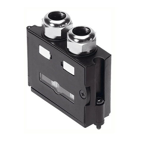
Adapter cable for the IO-Link connection via the interface [X1] of the integrated
drives EMCS.
Use for IO-Link Master Port Class A and IO-Link Master Port Class B.
Older adapters before product version 01/22 are only intended for use with
IO-Link Master Port Class A.
The product version can be seen on the adapter cable, e.g. "Festo NEFC-
M12G8-0,3-M12G5-LK 8080777 01/22 CE...".
Explanation of identification 01/22:
01 = calendar week
22 = year.
2.3 Training of qualified personnel
Work on the product may only be carried out by qualified personnel who can
evaluate the work and detect dangers. The qualified personnel are trained in
electrical engineering.
3 Structure
3.1 Product design
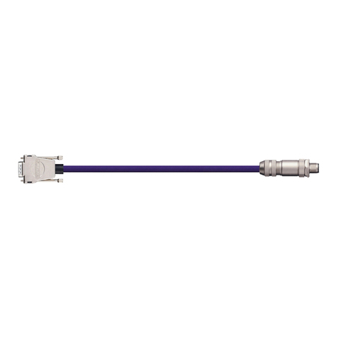
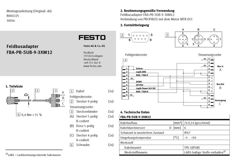
Fig.1
1Socket M12x1, A-coded
2Plug M12x1, A-coded
3Cable
3.2 Contact assignment
Electrical connection 1
Field device side
Electrical connection 2
Controller side
1 Socket Pin Pin 2 Plug con-
nector
1 1
2 not assigned 2 not assigned
3 4
4 3
5 … 8 not assigned 5 not assigned
Tab. 1: Contact assignment
4Assembly
4.1 Mounting of electrical connection 1
1. Align socket 1 to match plug.
2. Connect socket 1 to the plug.
3. Tighten the screw-type lock of the socket 1. Tightening torque:
0.4 Nm ± 55 %
4.2 Mounting of electrical connection 2
1. Align the plug 2 to match the socket.
2. Insert the plug 2 into the socket.
3. Tighten the screw-type lock of the plug 2. Tightening torque: 0.4 Nm ± 55 %
4.3 Wiring
Feature Cable characteristic Wiring
-E Suitable for energy chains in energy chain or flexible
Tab. 2: Wiring
4.4 Mounting in energy chain
1. Lay out the energy chain lengthways.
2. Place the cables in the energy chain without twisting them.
3. Separate cables from each other using separators/drilled holes.
4. Do not bind cables in bundles.
5. Maintain space X. X > 10% of the cable diameter D.
With the energy chain hanging vertically: increase the space X.
Align the energy chain in the working position:
–Make sure that the radius is greater than the bending radius R of the
cables.
–The cables can move freely in the bending radius KR of the energy chain.
ÄThe cable movement is not forced by the energy chain.
7. Mount the energy chain è corresponding instruction manual.
Fasten the cables:
–for short energy chains with a length < 1 m at both ends of the energy chain
–for long sliding energy chains with a length > 1 m at the driver end only
9. Do not move cables all the way to the fastening point.
ÄThe mounting space A between the fastening point and bending move-
ment is maintained.
NOTICE
Damage to cables if the chain breaks.
• Replace cables after a chain break.
