manuals.online logo
Brands
  1. Home
  2. •
  3. Brands
  4. •
  5. LOVATO ELECTRIC
  6. •
  7. Control Unit
  8. •
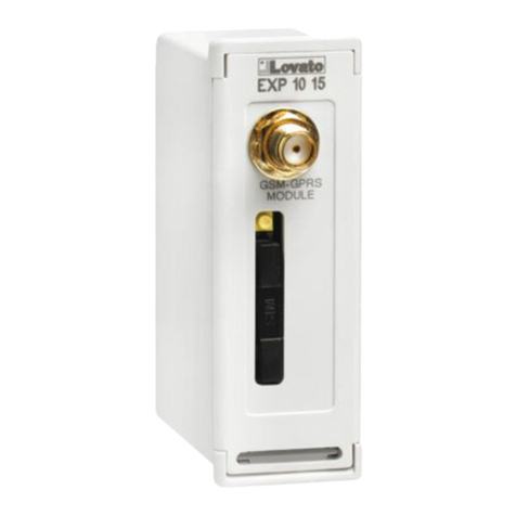
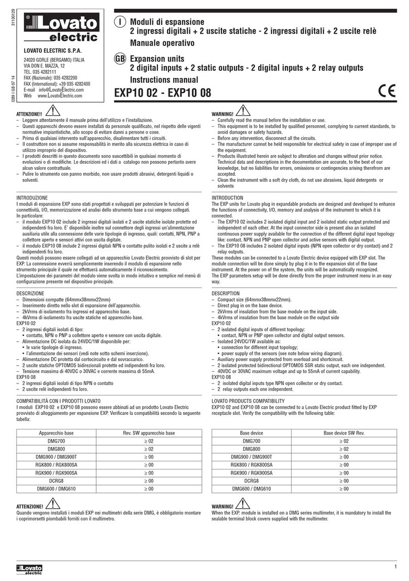
  9. LOVATO ELECTRIC EXP10 13 User manual

LOVATO ELECTRIC EXP10 13 User manual

Doc: 1MHIT100D0508_EXP1013 02/11/2009 p. 1 / 3
PL
EXP10 13 EXP10 13
Moduł rozszerzeń Expansion module
Izolowany port ETHE NET Isolated ETHE NET interface
INST UKCJA OBSŁUGI INST UCTIONS MANUAL
● Przed pracami serwisowymi, naleŜy odłączyć wszystkie napięcia od wejść
pomiarowych i zasilania pomocniczego oraz zewrzeć zaciski przekładnika
prądowego.
● Prod kty zaprezentowane w poniŜszym dok mencie mogą zostać zmienione
l b lepszone bez konieczności wcześniejszego informowania o tym.
● Dane techniczne oraz opisy oddają w jak najdokładniejszy sposób posiadaną
przez nas wiedzę, jednak nie bierzemy odpowiedzialności za ewent alne błędy,
braki oraz syt acje awaryjne.
● NaleŜy czyścić rządzenie delikatną s chą szmatką, nie naleŜy Ŝywać środków
ściernych, płynnych detergentów l b rozp szczalników.
● Remove the dangero s voltage from the prod ct before any maintenance
operation on it.
● Prod cts ill strated herein are s bject to alteration and changes witho t prior
notice.
● Technical data and descriptions in the doc mentation are acc rate, to the best
of o r knowledge, b t no liabilities for errors, omissions or contingencies arising
therefrom are accepted.
● Clean the instr ment with a soft dry cloth, do not se abrasives, liq id
detergents or solvents
Spis
treści
Strona
Wprowadzenie
1
Opis
1
Kompatybilność z prod ktami
Lovato
1
Proced ra podłączenia mod ł
2
F nkcje wskaźników LED
łącznika
RJ45 ETHERNET
2
Ustawianie parametrów mod ł
2
Schematy podłączeń
2
Wymiary mechaniczne
2
Charakterystyka techniczna
2
Index
Page
Introd
ction
1
Descripti
on
1
Lovato prod cts compatibility
1
Mod le connection proced re
2
RJ45 connector ETHERNET LED f nctions
2
Mod le parameters set p
2
Wiring diagrams
2
Mechanical
dimensions
2
Technical charact
eristics
2
Wprowadzenie
Mod ły EXP dedykowane są do prod któw z moŜliwością rozszerzenia
przez gniazda wtykowe i zostały zaprojektowane by zwiększyć moŜliwość
typ podłączenia, dostępność wejść/wyjść i zapamiętywanie
i analizę pomiarów z rządzenia do którego jest podłączony. EXP1013
moŜliwia podłączenie miernika przez port ETHERNET i moŜe być
podłączony do kaŜdego z rządzeń Lovato, które wyposaŜone jest
w gniazda wtykowe. Przyłączenia dokon je się szybko do jednostki
bazowej. Po podłączeni zasilania kład a tomatycznie rozpozna typ
mod ł EXP.
Intro
duction
The EXP nits for Lovato pl g in expandable prod cts are designed and
developed to enhance the f nctions of connectivity, I/O, memory and
analysis of the instr ment to which it is connected.
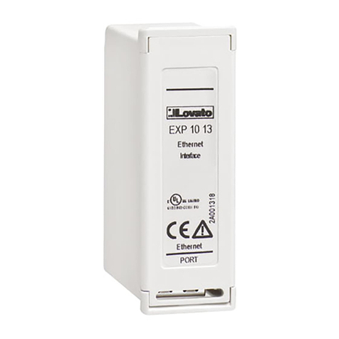
The EXP10 13 implements the isolated ETHERNET serial interface and
its connection will be done simply by pl g it in to the expansion slot of the
base instr ment. At the power on of the system, the instr ment will
a tomatically recognize the nits and the EXP parameters set p will be
done directly from the proper instr ment men in an easy way.
Opis
• Wymiary kompaktowe (64mmx38mmx22mm)
• MontaŜ wtykowy do jednostki bazowej.
• Izolacja od jednostki bazowej 2KVrms przez 1 min tę.
• 10/100 Mbps ETHERNET.
• Protokoły TCP/IP.
• Dw kolorowa dioda LED (2 stat sy) na łączniki RJ45 do sygnalizacji
stat s ETHERNET.
• A tomatyczne rozpoznanie przez rządzenie do którego jest
podłączony.
• Ustawianie parametrów EXP przez men rządzenia.
Description
• Compact size (64mmx38mmx22mm).
• Direct pl g in on the base instr ment.
• 2KVrms for 1 min te of ins lation from the base mod le.
• 10/100 Mbps ETHERNET .
• TCP/IP protocol.
• 2 stat s d ble-color LED on the RJ45 connector for the
ETHERNET stat s.
• A tomatically recognition by the instr ment to which is connected
• EXP config ration from the proper instr ment men .
Kompatybilność z produktami Lovato
Mod ł rozszerzeń EXP10 13 moŜe być podłączony do wszystkich
rządzeń Lovato posiadających gniazda wtykowe. NaleŜy sprawdzić
moŜliwość podłączenia danego mod ł w tabeli poniŜej:
Lovato products compatibilit
y
EXP10 13 expansion nit can be connected to a Lovato prod ct fitted by
EXP pl g in receptacle slot. Verify the compatibility with the following
table:
I296
PL
GB 1109
UWAGA
!!
● NaleŜy dokładnie zapoznać się z poniŜsza instr kcją przed
instalacją l b Ŝywaniem rządzenia.
● By niknąć szkodzęń i zagroŜenia Ŝycia rządzenia
te powinny być instalowane przez wykwalifikowany personel,
i w zgodzie z
odpowienimi przepisami.
WA NING!
• Caref lly read the man al before the installation or se.
• This eq ipment is to be installed by q alified personnel,
complying to c rrent standards, to avoid damages or safety
Doc: 1MHIT100D0508_EXP1013 02/11/2009 p. 2 / 3
EXP 10 13
Urządzenie bazowe
ewizja oprogramowania
SW
DMG800
>= 01
EXP 10 13
Base device
Base device SW ev.
DMG800
>= 01
Procedura podłączenia moduł
u
Module
connection procedure
1.
Odłączyć niebezpieczne napięcie
.
2. NaleŜy zdjąć osłonę zacisków i zaciski przyłączeniowe.
3. Następnie naleŜy zdjąć osłonę otwor montaŜowego w prod kcie
Lovato, w miejsc gdzie EXP będzie zamontowany.
4. NaleŜy włoŜyć mod ł EXP10 13 tak by klips montaŜowy znalazł
się w dzi rce powyŜej otwor montaŜowego i stanowił oś oparcia
podczas wkładania mod ł .
5. NaleŜy mieścić mod ł EXP w otworze montaŜowym poprzez
niewielki r ch.
6. NaleŜy ponownie mieścić osłonę zacisków i zaciski przyłączeniowe.
7. Następnie włączyć zasilanie (jednostka bazowa a tomatycznie
rozpozna podłączony mod ł).
8. Następnie naleŜy skonfig rować mod ł zgodnie z instr kcją obsł gi.
UWAGA: w cel s nięcia mod ł EXP (przy odłączonym zasilani
i wymontowanych zaciskach przyłączeniowych, które mogą przeszkadzać
w demontaŜ ) naleŜy wcisnąć p nkt wskazany gwiazdką (*) i wyciągnąć
mod ł.
1.
Remove any dangero s voltage
.
2. Remove the terminal covers and the terminal block.
3. Remove the expansion slot cover of the Lovato prod ct at the
position in which the EXP will be pl g in.
4. Insert the EXP10 13 so that its pper hook enters into the
hole present above the expansion slot playing in this way the
f nction of pivot d ring insertion.
5. Bring the EXP at the complete insertion by a little circ lar
motion.
6. Re-position the terminal block and the terminal cover.
7. Power p the system (the base prod ct will a tomatically
recognize the expansion nit).
8. Config re the mod le by following the programming indication
presents on the instr ment man al.
NOTE: in order to p ll o t the EXP (having removed the dangero s
voltage and possible terminal blocks which hinder the removal) press the
point indicated by the * and extract the mod le.
Funkcje wskaźników LED na łączniku J45 ETHE NET
POSIZIONE
COLO E
DESC IZIONE
LED
po LEWEJ
(podłączenie)
OFF
Zielona
B rsztynowa
B
rak
podłączenia
100Mbps
10Mbps
LED
po
PRAWEJ
(aktywność)
OFF
Zielona
B rsztynowa
B
rak
aktywności
F ll D plex
Half D plex
J45 connector ETHE NET LED functions
POSITION
COLO
DESC IPTION
LEFT LED
(Link)
OFF
Green
Amber
No link
100Mbps
10Mbps
RIGHT LED
(activity)
OFF
Green
Amber
No activity
F ll D plex
Half D plex
Ustawianie parametrów modułu
W cel stawienia parametrów mod ł EXP naleŜy zapoznać
się z instr kcją główną rządzenia bazowego.
NaleŜy skontaktować się z administratorem sieci w cel stalenia
parametrów dla mod ł Ethernet.
Module parameters setup
For the EXP parameters config ration, see the man al of the main
prod ct to which it intends to connect.
Refer to network administrator for the Ethernet mod le parameters
reservation
CLAC!
1 2 3
*
UWAGA
!
● Kiedy mod ł EXP jest zamontowany w miernik DMG,
naleŜy koniecznie zamontować osłonę zacisków
dostarczaną z miernikiem.
WA NING!
• When the EXP.. mod le is installed on a DMG series
m ltimeter, it is mandatory to install the sealable
terminal block covers s pplied with the m ltimeter.
Doc: 1MHIT100D0508_EXP1013 02/11/2009 p. 3 / 3
Schemat podłączeń
Wiring diagram
Wymiary mechaniczne [mm]
Mechanical dimensions
[
mm
]
Interfejs ETHE NET
ETHE NET interface
Interfejs sieci
RJ45 Ethernet 10BASE
-
T
l b
100BASE-TX (a to-sensing)
Network Interface
RJ45 Ethernet 10BASE
-
T or
100BASE-TX (a to-sensing)
Zgodność
Ethernet:
wersja
2.0/IEEE80
2.3
Compatibility
Ethernet: Version 2.0/IEEE802.3
Podłaczenie portu ETHE NET
ETHE NET port connection
Typ łącznika
RJ45
Connector type
RJ45
Podłączenie do jednostki bazowej
Base product connection
Typ podłączenia
wtykowe
Terminal type
Pl g
-
in connector
Napięcie izolacji
Insula
tion voltage
Znamionowe napięcie wytrzymywane
izolacji Uimp
4
kV
Rated imp lse withstand voltage Uimp
4
kV
Napięcie wytrzymywane częstotliwości
sieci
2kV
Power freq ency withstand voltage
2kV
Warunki otoczenia pracy
Ambient operating conditi
ons
Temperat ra pracy
-
20
-
+60°C
Operating temperat re
-
20
-
+60°C
Temperat ra składowania
-
30
-
+80°C
Storage temperat re
-
30
-
+80°C
Wilgotność względna
<
90%
Relative h midity
<
90%
Maksymalny stopień zanieczyszczenia
Stopień
2
Maxim m poll tion degre
e
Degree 2
Kategoria przeciąŜeniowa
3
Overvoltage category
3
Wysokość
≤2000m
Altit de
≤2000m
Dane techniczne
Tech
nical characteristics
Obudowa
Housing
Wymiary
64,5mmx38,2mmx22mm
Dimensions
64.5
mmx38
.2
mmx22mm
MontaŜ
W otworze montaŜowym, wt
ykowy
Mo ntin
g
For incl sion in the
EXP pl g in
expansion slot
Materiał
Poliamid
RAL 7035
Material
Polyamide RAL7035
Stopień ochrony
IP20
Degree of protection
IP20
Masa
64
g
Weight
64
g
Uznania i normy
Certifications and compliance
Zgodne z normami
IEC/EN 61010
-
1:2001, IEC/EN 61000
-
6
-
2:2005,
EN 61000-4-3:2006, EN 61000-6-3:2001,
IEC/EN 60068-2-61:1993, IEC/EN 60068-2-78,
IEC/EN 60068-2-6, IEC 60068-2-27.
Reference standards
IEC/EN 61010
-
1:2001, IEC/EN 61000
-
6
-
2:2005,
EN 61000-4-3:2006, EN 61000-6-3:2001,
IEC/EN 60068-2-61:1993, IEC/EN 60068-2-78,
IEC/EN 60068-2-6, IEC 60068-2-27

Other LOVATO ELECTRIC Control Unit manuals

LOVATO ELECTRIC EXS4000 User manual

LOVATO ELECTRIC

LOVATO ELECTRIC EXS4000 User manual

LOVATO ELECTRIC GEX69 C Series User manual

LOVATO ELECTRIC

LOVATO ELECTRIC GEX69 C Series User manual

LOVATO ELECTRIC RGK800 User manual

LOVATO ELECTRIC

LOVATO ELECTRIC RGK800 User manual

LOVATO ELECTRIC RGK900MC User manual

LOVATO ELECTRIC

LOVATO ELECTRIC RGK900MC User manual

LOVATO ELECTRIC EXP10 30 User manual

LOVATO ELECTRIC

LOVATO ELECTRIC EXP10 30 User manual

LOVATO ELECTRIC EXM1013 User manual

LOVATO ELECTRIC

LOVATO ELECTRIC EXM1013 User manual

LOVATO ELECTRIC EXM 10 01 User manual

LOVATO ELECTRIC

LOVATO ELECTRIC EXM 10 01 User manual

LOVATO ELECTRIC EXP10 04 User manual

LOVATO ELECTRIC

LOVATO ELECTRIC EXP10 04 User manual

LOVATO ELECTRIC EXP10 14 User manual

LOVATO ELECTRIC

LOVATO ELECTRIC EXP10 14 User manual

LOVATO ELECTRIC EXP10 30 User manual

LOVATO ELECTRIC

LOVATO ELECTRIC EXP10 30 User manual

LOVATO ELECTRIC EXP10 02 User manual

LOVATO ELECTRIC

LOVATO ELECTRIC EXP10 02 User manual

LOVATO ELECTRIC EXP10 31 User manual

LOVATO ELECTRIC

LOVATO ELECTRIC EXP10 31 User manual

LOVATO ELECTRIC EXP10 15 User manual

LOVATO ELECTRIC

LOVATO ELECTRIC EXP10 15 User manual

LOVATO ELECTRIC RGK800SA User manual

LOVATO ELECTRIC

LOVATO ELECTRIC RGK800SA User manual

LOVATO ELECTRIC EXP10 14 User manual

LOVATO ELECTRIC

LOVATO ELECTRIC EXP10 14 User manual

LOVATO ELECTRIC ATL DPS1 User manual

LOVATO ELECTRIC

LOVATO ELECTRIC ATL DPS1 User manual

LOVATO ELECTRIC RGK700 User manual

LOVATO ELECTRIC

LOVATO ELECTRIC RGK700 User manual

LOVATO ELECTRIC EXP10 30 User manual

LOVATO ELECTRIC

LOVATO ELECTRIC EXP10 30 User manual

LOVATO ELECTRIC EXP10 10 User manual

LOVATO ELECTRIC

LOVATO ELECTRIC EXP10 10 User manual

LOVATO ELECTRIC ATL DPS1 User manual

LOVATO ELECTRIC

LOVATO ELECTRIC ATL DPS1 User manual

LOVATO ELECTRIC EXS4000 User manual

LOVATO ELECTRIC

LOVATO ELECTRIC EXS4000 User manual

LOVATO ELECTRIC RGK800 User manual

LOVATO ELECTRIC

LOVATO ELECTRIC RGK800 User manual

LOVATO ELECTRIC VLBX C Series User manual

LOVATO ELECTRIC

LOVATO ELECTRIC VLBX C Series User manual

LOVATO ELECTRIC EXP10 13 User manual

LOVATO ELECTRIC

LOVATO ELECTRIC EXP10 13 User manual

Popular Control Unit manuals by other brands

Enerpac VSP Series instruction sheet

Enerpac

Enerpac VSP Series instruction sheet

C&H Technologies VX462B user manual

C&H Technologies

C&H Technologies VX462B user manual

GSD W2TM2510 user manual

GSD

GSD W2TM2510 user manual

Evenlite ELCD Installation & operation manual

Evenlite

Evenlite ELCD Installation & operation manual

Digital deep sea DSE5220 operating manual

Digital deep sea

Digital deep sea DSE5220 operating manual

System Sensor MDl Series Installation and maintenance instructions

System Sensor

System Sensor MDl Series Installation and maintenance instructions

Hillstone SG-6000 X-Series reference guide

Hillstone

Hillstone SG-6000 X-Series reference guide

Waves MDMX Screamer user guide

Waves

Waves MDMX Screamer user guide

BERMAD 420 maintenance

BERMAD

BERMAD 420 maintenance

NSK ASTRO-E 250 Operation manual

NSK

NSK ASTRO-E 250 Operation manual

Dickey-John Land Manager SE manual

Dickey-John

Dickey-John Land Manager SE manual

KSB BOAX-B Series operating instructions

KSB

KSB BOAX-B Series operating instructions

Olympia P-240XB Installation

Olympia

Olympia P-240XB Installation

Danfoss VHX-DUO Mounting guide

Danfoss

Danfoss VHX-DUO Mounting guide

Arduino Nano 33 BLE Rev2 Product reference manual

Arduino

Arduino Nano 33 BLE Rev2 Product reference manual

Emerson SAPAG Installation & maintenance instructions

Emerson

Emerson SAPAG Installation & maintenance instructions

TP-Link DS-PMA-C+ V1 installation guide

TP-Link

TP-Link DS-PMA-C+ V1 installation guide

Quectel GNSS Module Series user guide

Quectel

Quectel GNSS Module Series user guide

manuals.online logo
manuals.online logoBrands
  • About & Mission
  • Contact us
  • Privacy Policy
  • Terms and Conditions

Copyright 2025 Manuals.Online. All Rights Reserved.