manuals.online logo
Brands
  1. Home
  2. •
  3. Brands
  4. •
  5. Festo
  6. •
  7. Control Unit
  8. •
  9. Festo PREL-186 User manual

Festo PREL-186 User manual

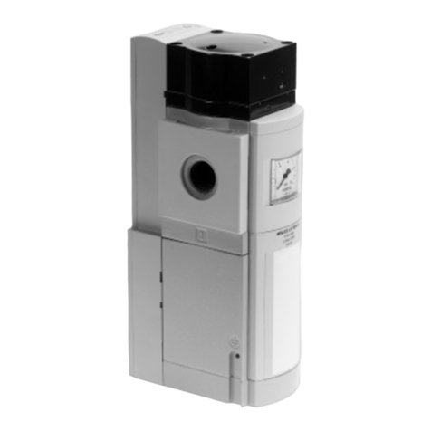
Pressure regulating valve
PREL-186
Festo AG & Co. KG
Ruiter Straße 82
73734 Esslingen
Germany
+49 711 347-0
www.festo.com
Operating instructions
Translation of the original instructions
8084640
2017-11b
[8084642]
For all available product documentation èwww.festo.com/pk
Pressure regulating valve PREL-186 English..............................
1 Design
1aE
2
3
4
5
6
78
9
aJ
aA
aB
aC
aD
aD
aE
PREL-186-...-40CFX2PREL-186-...-40CFX
1Compressed air supply port (input)
– [1]
2Slots for mounting the module
connectors
3Exhaust port G1 – [3]
4Exhaust port, pilot valve G½– [82]
5Silencer (scope of delivery)
6Proportional pressure regulator
VPPL (scope of delivery, pre-as
sembled)
7Service interface (socket M12)1)
8Output connection actual value
(plug connector M12)
9Input connection setpoint value /
voltage supply (plug connector
M12)
aJ Exhaust module PAHL (-...X2)
aA Alternative exhaust port, pilot
valve G½– [82]
aB Alternative exhaust port 1" – [3]
aC Supply port (output) – [2]
aD Pneumatic port G¼(output pres
sure p2) for pressure gauge or
pressure sensor – [22]
aE Pneumatic port G¼(inlet pressure
p1) for pressure gauge or pressure
sensor – [11]
1) The diagnostics interface should only be used by Festo service staff.
Fig. 1
2 Function
Note
The pressure regulator PREL can only be operated together with the proportional-
pressure regulator VPPL.
 Observe the operating instructions for the proportional pressure regulator
VPPL.
The output pressure of the PREL pressure regulating valve VPPL is determined by
an integrated pressure sensor and internally compared to the setpoint value. In
case of deviations, the VPPL actuates the controller of the pressure regulator PREL
until the output pressure reaches the setpoint value.
In basic setting (no setpoint specification), the output pressure is reduced with the
vent seat fully open.
The -40CFX2variant is additionally equipped with the two-channel PAHL exhaust
module. With the integrated solenoid valves and sensors and in combination with
an external controller, it serves to implement the safety function “Safe venting” in
accordance with DIN EN ISO 13849-1:2008-12, performance level “d”, èPAHL
operating instructions.
3 Application
The pressure regulating valve PREL-186 is intended to regulate the air pressure in
the subsequent string to an electrically specified output pressure.
 Only use the product in original status without unauthorised modifications. Only
the mounting and commissioning activities described in these operating instruc
tions are permissible.
 Observe all permissible limit values and specifications (èTechnical data).
 Only use the product if it is in an excellent technical status.
 Only use pre-filtered compressed air as an operating medium in accordance with
the specification (èTechnical data).
 Operation with fluids or gases is impermissible.
 Use the pressure regulating valve only in the marked flow direction.
 Comply with all applicable national and international regulations.
4 Installation
Note
 Installation only by qualified personnel and only in accordance with the oper
ating instructions.
 For direct mounting of an individual device, connecting plates of the type
PAML-CP-186-HP3-... are required.
 Information on mounting of module connectors, connecting plate and mounting
brackets can be found in the documentation enclosed with the accessories.
aF
aG
Fig. 2
1. Check the system requirements on site before installation:
– The piping is unpressurized, and no medium flows in it.
– The supply lines are clean and free of wear-causing particles.
– Shut-off valves for venting the system are mounted in the compressed air
supply line.
2. Mount silencers 5(included in scope of delivery) to the exhaust port 4.
3. Mount an additional silencer (èAccessories) to the exhaust port 3.
4. Bring pressure regulating valve into its mounting position (èTechnical data).
– Observe the flow direction. The numerals 1 (input side) and 2 (output side) on
the product housing can be used for orientation (èFig. 1).
– Mounting position: vertical with the VPPL 6on top (èFig. 2) or turned 180°
(VPPL underneath).
5. Push the module connector aF into the slots of the pressure regulator and the
adjacent service unit.
6. Connect the pressure regulating valve to the adjacent service unit.
– Place the supplied seal aG at the connection point.
– Push the pressure regulating valve and adjacent service unit together and
fasten the module connector.
7. Mount devices together to create a service unit, then connect this completely to
the compressed air line.
8. Check connection points for tightness.
Mounting the proportional pressure regulator VPPL
Mounting of the proportional pressure regulator VPPL to the pressure regulating
valve PREL is described in the operating instructions of the VPPL.
The VPPL is pre-assembled on delivery.
5 Electrical connection
Warning
Electric voltage
Injuries caused by electric shock, damage to the machine and system.
 Electrical connection may be made only by qualified personnel.
 For the electrical power supply, use only PELV power circuits in accordance
with IEC60204-1/A1 (Protective Extra Low Voltage, PELV).
 Take account of the general requirements of IEC60204-1 for PELV power circuits.
 Use only voltage sources that ensure a reliable electric separation of operat
ing voltage in accordance with IEC60204-1.
1. Use pre-assembled cables from Festo.
2. Before establishing the electrical connection, check the connecting cable:
– Max. length of the signal lines: 30 m.
– The cables are installed free of crimping, kinking and stretching.
3. Connection of two-channel exhaust module, èOperating instructions PAHL
Note
The connection 7is used only for diagnostics. If this plug connector is used for
operation of the valve, it can result in damage to the electronic controls.
 Never connect port 7to the power supply.
 Always keep port 7closed with a cover cap.
4. Screw signal cable onto port 8(èFig. 1).
– Pin allocation for M12 plug:
– Tightening torque 0.5 Nm ±20 %.
Pin Cable colour1) Assignment M12 plug connector
1 – Unused 1
2
35
4
2White (WH) Analogue out+ (actual value)
3 – Unused
4Black (BK) Analogue out– (actual value)
5Grey (GY) FE
1) When using the pre-assembled Festo cables
Fig. 3
Note
With use of a screened cable:
 Earth screening on the cable end away from the VPPL.
5. Screw the connecting cable to the port 9(èFig. 1).
– Pin allocation for M12 plug:
– Tightening torque 0.5 Nm ±20 %.
Pin Cable colour1) Assignment M12 plug connector
1Brown (BN) 24 V DC 1
2
35
4
2White (WH) Analogue In+ (setpoint value)
3Blue (BU) 0 V
4Black (BK) Analogue in– (setpoint value)
5Grey (GY) FE
1) When using the pre-assembled Festo cables
Fig. 4
6 Commissioning
Note
The pressure regulator PREL can only be operated together with the proportion
al-pressure regulator VPPL.
 Commissioning should only be conducted by qualified personnel.
 Note operating instructions of the proportional pressure regulator PREL.
 With variant -40CFX2: Observe the operating instructions of the PAHL shut-off
valve.
1. Prior to commissioning, check the following requirements:
– The VPPL is flange-mounted to the PREL.
– The PREL is completely connected and ready for operation.
– The connection points are tight.
– Any necessary safety equipment is present and active.
2. Switch on the supply voltage.
3. Switch on supply pressure.
4. Switch on analogue setpoint signal (0 … 10 V/4 … 20 mA).
5. Place the VPPL and PREL into operation together (èVPPL operating instructions).
Note
The pressure regulating valve PREL has an integrated soft start function. That
means, when a setpoint value is being applied, the pressure rise at the output of
the pressure regulating valve is delayed.
7 Operation
Note
To avoid malfunctions of the setpoint value signal:
 Keep sources of high frequency electromagnetic radiation (e.g. radios, mobile
phones, other interfering transmitters) away from the device.
 Comply with operating conditions.
 Always comply with the permissible limits.
 Observe the operational status displays of the VPPL (èOperating instructions
VPPL).
Safety setting: In case of a wire break, the output pressure is lowered to
0 bar.
The VPPL interprets setpoint signals less than 1 % of full scale as 0 V.
In this case, the working pressure is set to ambient pressure.
8 Maintenance and care
Warning
Risk of injury from compressed air.
Products under pressure can cause personal injury and material damage.
 Maintenance only by qualified personnel.
 Before all maintenance work, depressurize the valve, service unit and piping.
Prior to all maintenance work:
1. Switch off pressure to valve and adjacent pneumatic devices.
2. Switch off analogue setpoint signal.
3. Let the device cool off.
4. Switch off supply voltage and safeguard it against being switched on again.
Cleaning:
 Regularly clean the outside of the product with a soft cloth.
The permissible cleaning agent is water or soap suds (max. 50 °C).
9 Dismantling
Warning
Risk of injury from compressed air.
Products under pressure can cause personal injury and material damage.
 Dismounting only by qualified personnel.
 Before all disassembly work, depressurize the valve, service unit and piping.
Caution
Risk of injury from falling loads.
 Take the weight of the individual device or a service unit into consideration. De
pendent on the design, an installed service unit can weigh more than 100 kg.
1. Switch off pressure to the pneumatic system.
2. Switch off analogue setpoint signal.
3. Let the device cool off.
4. Switch off supply voltage and safeguard it against being switched on again.
5. Disconnect electrical connections of the VPPL.
6. Shut down the PREL and VPPL together.
7. Remove the service unit.
– If installed before or after the service unit: Remove the compressed air line or
the connecting plate on the service unit.
– If installed between two service units: Loosen the screws of the module con
nector.
10 Fault clearance
Warning
Risk of injury from compressed air/pressure surge.
Products under pressure can cause personal injury and material damage.
 Before applying the supply pressure: Set the setpoint value of the VPPL to zero.
Malfunction Display Possible cause Remedy
The valve
switches off
after 5 s
LED status at
the VPPL
flashes red
Supply pressure lacking 1. Set setpoint value to zero
2. Apply supply pressure
3. Set required setpoint value
Fig. 5
Note
For additional information on fault clearance èOperating instructions VPPL
11 Accessories
Designation Product type
Sub-base PAML-CP-186-HP3
Module connector PAML-MK-186-HP3
Propor tional pressure regulator VPPL
Pneumatic silencers U-G1-HD-SA
Fig. 6
12 Technical data
PREL-186 -40CFX -40CFX2
Supply pressure p1 [bar] 0 … 50
Auxiliary pilot air connection (to PAHL) – G¼
Pressure range, auxiliary pilot air [bar] –6 … 10
Pressure regulation range [bar] 0.4 … 40
Signal setpoint
value
(Analogue input)
Voltage [V DC] 0 … 10
Current [mA] 4 … 20
Operating voltage [V DC] 21.6 … 27.6
Operating medium Compressed air to ISO 8573-1:2010 [7:4:4]
Inert gases
Temperature of medium [°C] +5 … +50
Ambient temperature [°C] +5 … +50
Mounting position Vertical with VPPL on top
Alternative mounting position Vertical with VPPL underneath
Flow direction Marking on the housing: from 1 to 2
Type of mounting – In-line installation
– Module connector
– Sub-bases
Classification in accordance with
Pressure Equipment Directive
Category I
CE marking (see declaration of
conformity) 1) èwww.festo.com/sp
– According to EC Pressure
Equipment Directive
– According to EC Pressure
Equipment Directive
– In accordance with the
EC Machinery Directive
Max. cable length [m] 30
Weight [kg] 37.1 40.4
1) The device is intended for use in an industrial environment.
Measures for interference suppression may need to be implemented in residential areas.
Fig. 7
Dependence of p1 on p2max
PREL-186-HP3-...-40...
Fig. 8
Pressure ramp at switch-on of the PREL
(Not activated with ongoing controlled operation)
PREL-186-...-40...
Fig. 9

Other Festo Control Unit manuals

Festo CPX-FB14 Parts list manual

Festo

Festo CPX-FB14 Parts list manual

Festo CPX-FVDA-P2 User manual

Festo

Festo CPX-FVDA-P2 User manual

Festo CPA-SC-DP Parts list manual

Festo

Festo CPA-SC-DP Parts list manual

Festo CPX-E-EP User manual

Festo

Festo CPX-E-EP User manual

Festo CTEU-DN Parts list manual

Festo

Festo CTEU-DN Parts list manual

Festo MS6N-SV Installation instructions

Festo

Festo MS6N-SV Installation instructions

Festo CHB-C-N User manual

Festo

Festo CHB-C-N User manual

Festo MPYE-5-***-B series User manual

Festo

Festo MPYE-5-***-B series User manual

Festo VZQA-C-M22C-6-GG-V2V4E-2 Parts list manual

Festo

Festo VZQA-C-M22C-6-GG-V2V4E-2 Parts list manual

Festo SMH-AE1 M12 Series User manual

Festo

Festo SMH-AE1 M12 Series User manual

Festo LF-D Series User manual

Festo

Festo LF-D Series User manual

Festo CPX-FVDA-P Parts list manual

Festo

Festo CPX-FVDA-P Parts list manual

Festo CAMC-G-S3 User manual

Festo

Festo CAMC-G-S3 User manual

Festo VACC-S18-35-K4-1U-EX4ME User manual

Festo

Festo VACC-S18-35-K4-1U-EX4ME User manual

Festo DG Series User manual

Festo

Festo DG Series User manual

Festo VZXA Series Setup guide

Festo

Festo VZXA Series Setup guide

Festo CPX-AP-I-8DI-M12-5P Parts list manual

Festo

Festo CPX-AP-I-8DI-M12-5P Parts list manual

Festo CPX-FVDA-P2 User manual

Festo

Festo CPX-FVDA-P2 User manual

Festo FLSM User manual

Festo

Festo FLSM User manual

Festo CPX-E-1CI User manual

Festo

Festo CPX-E-1CI User manual

Festo MS4-A-IPM-80 User manual

Festo

Festo MS4-A-IPM-80 User manual

Festo VTSA Series Parts list manual

Festo

Festo VTSA Series Parts list manual

Festo VIFB-21 Series User manual

Festo

Festo VIFB-21 Series User manual

Festo MS6-SV Series User manual

Festo

Festo MS6-SV Series User manual

Popular Control Unit manuals by other brands

Spirax Sarco BM series Installation and maintenance instructions

Spirax Sarco

Spirax Sarco BM series Installation and maintenance instructions

AVer CB-310 user manual

AVer

AVer CB-310 user manual

Bull ESCALA Power7 5802 Installing

Bull

Bull ESCALA Power7 5802 Installing

GEM 539 eSyDrive operating instructions

GEM

GEM 539 eSyDrive operating instructions

Keysight Technologies 81650A user guide

Keysight Technologies

Keysight Technologies 81650A user guide

Accutrol AVC5000 Installation & operation manual

Accutrol

Accutrol AVC5000 Installation & operation manual

Siemens multiranger 200 Application guide

Siemens

Siemens multiranger 200 Application guide

V2 LUX2+ manual

V2

V2 LUX2+ manual

Videx 4000 Series manual

Videx

Videx 4000 Series manual

FAAC E024S manual

FAAC

FAAC E024S manual

H. B. Fuller Cyberbond CB LINOP U 500 operating instructions

H. B. Fuller

H. B. Fuller Cyberbond CB LINOP U 500 operating instructions

Chargery BMS16Pro Series manual

Chargery

Chargery BMS16Pro Series manual

Rockwell Automation Allen-Bradley Micro800 manual

Rockwell Automation

Rockwell Automation Allen-Bradley Micro800 manual

Burkert 2730 Series operating instructions

Burkert

Burkert 2730 Series operating instructions

NI PXIe-7972R Getting started guide

NI

NI PXIe-7972R Getting started guide

Pilz PIT es Set/1 operating manual

Pilz

Pilz PIT es Set/1 operating manual

Aaeon COM-KB user manual

Aaeon

Aaeon COM-KB user manual

Simplex TYCO 4905-9835 quick start guide

Simplex

Simplex TYCO 4905-9835 quick start guide

manuals.online logo
manuals.online logoBrands
  • About & Mission
  • Contact us
  • Privacy Policy
  • Terms and Conditions

Copyright 2025 Manuals.Online. All Rights Reserved.