manuals.online logo
Brands
  1. Home
  2. •
  3. Brands
  4. •
  5. Festo
  6. •
  7. Control Unit
  8. •
  9. Festo VZQA-C-M22U series User manual

Festo VZQA-C-M22U series User manual

Pinch valve
VZQA-C-M22U-…
Festo AG & Co. KG
Ruiter Straße 82
73734 Esslingen
Germany
+49 711 347-0
www.festo.com
Operating instructions
(Original instructions)
8071015
1704f
[8071017]
Pinch valve VZQA-C-M22U English......................................
For all available product documentation èwww.festo.com/pk
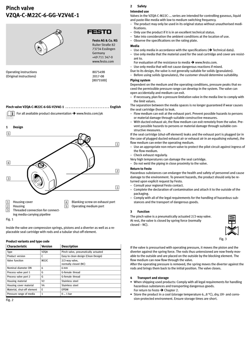
1 Design
1
3
2
4
1Housing cover
2Housing
3Threaded connection or clamp for
connecting media-carrying pipeline
4Operating medium port
Fig. 1
Inside the valve is a replaceable seal cartridge with a tubular shut-off element.
Accessories èwww.festo.com/catalogue.
Product variants and type code
Characteristic Value Description
Type VZQA Pinch valve, pneumatically actuated
Product version CEasy to clean design (Clean Design)
Valve function M22U 2/2-way valve,
normally open
Nominal diameter DN 6, 15, 25 6 mm, 15 mm, 25 mm
Process valve port 1 G, T, S1, S5, S12 G-female thread, NPT-female thread, clamp
Process valve port 2 G, T, S1, S5, S12 G-female thread, NPT-female thread, clamp
Housing material V4, AL Stainless steel, aluminium
Housing cover material V4, AL, POM Stainless steel, aluminium, polyoxymethylene
Shut-off element material N, E, S1 NBR, EPDM, silicone
Pressure range of media 40 … 4 bar
Fig. 2
2 Safety
Intended use
Valves in the VZQA-C-M22U-... series are intended for controlling liquid, gaseous,
powdery and solid media (granules) as well as mixtures of materials in piping sys
tems.
The valve VZQA-C-M22U-...-S1-... (shut-off element made of silicone) can be used
in food zones (declaration of conformity èwww.festo.com).
– The product may only be used in its original status without unauthorised modi
fications.
– Only use the product if it is in an excellent technical status.
– Take into consideration the ambient conditions at the location of use.
– Observe the specifications on the rating plate.
– Comply with all applicable national and international regulations.
Media
– Use only media in accordance with the specifications (èTechnical data).
– Use only media that the material used for the seal cartridge and cover are resist
ant to.
For evaluation of the resistance to media èwww.festo.com.
– Use only media that will not cause dangerous reactions if mixed.
Piping
Dependent on the medium and the operating conditions, pressure peaks that ex
ceed the permissible pressure range can develop in the system.
If the seal cartridge (shut-off element) fails, the operating medium can enter the
medium circuit. The pressure in the medium circuit can rise accordingly.
– Design the medium circuit for at least the set operating pressure.
– If necessary, plan for a pressure relief valve in the media line to comply with the
limit values.
Separation between the media spaces is no longer guaranteed if there is leakage
in the seal cartridge (shut-off element). Flow medium can then get into the control
circuit and escape (e.g. at a silencer).
– Use an appropriate non-return valve to protect the pilot circuit against ingress of
the flow medium.
– Secure possible medium exit points so that nobody can come into contact with
the medium.
The service life of the seal cartridge depends on the medium used, the operating
pressure and the switching speed.
– Limit the switching speed through a suitable flow control valve or control valve
(èFig. 4).
Very high temperatures can damage the seal cartridge.
– Do not weld the piping in close proximity to the valve.
Returning to Festo
Hazardous substances can endanger the health and safety of personnel and cause
damage to the environment. To prevent hazards, the product should only be retur
ned upon explicit request by Festo.
– Consult your regional Festo contact.
– Complete the declaration of contamination and attach it to the outside of the
packaging.
– Comply with all legal requirements for the handling of hazardous substances
and the transport of dangerous goods.
3 Function
The pinch valve is a pneumatically actuated 2/2-way valve.
The valve is open when at rest (normally open - NO).
If the valve is pressurised with operating pressure, the hose-
shaped shut-off element is pinched closed. The valve closes.
After removal of the operating pressure, the shut-off element
opens through its intrinsic tension and the medium pressure. Fig. 3
The free passage when the valve is opened ensures minimum flow resistance and
prevents the valve becoming blocked or clogged.
4 Transport and storage
 When shipping used products: Comply with all legal requirements for handling
hazardous substances and transporting dangerous goods.
For return to Festo èChapter 2.
 Store the product in a cool (storage temperature 8 °C), dry, UV- and corrosion-
protected environment. Ensure storage times are short.
5 Installation
Note
Installation should only be conducted by qualified specialized personnel.
Do not reach into the opening of the valve.
Requirements
– The piping system is unpressurised, and no medium flows in it.
– The lines are clean.
– The line ends are mounted.
– The system-provided safeguardings are installed (e.g. throttle valve or control
valve, non-return valve, pressure relief valve).
VZQA-C-M22U-... -6 -15 -25
Throttle valve /
control valve
Standard nominal flow rate (recommended) [l/min] 10 40 40
Nominal width (recommended) [mm] 0.5 1 1
Fig. 4
Clean valve
 Remove all transport packaging. The material used in the packaging has been
specifically chosen for its recyclability (exception: oil-impregnated paper = re
sidual waste).
Residues of grease may be evident on the product due to the production process
used.
 Clean valve immediately before installation.
Connect medium lines
Note
To eliminate direct access to the valve opening during operation, connect a line
to both ports, even if the valve is located at the end of the piping.
For product variants with female thread:
 Screw the valve connections to the medium line.
– Tightening torque èFig. 8.
For product variants with clamp:
 Place the clamp ferrule of the line and the clamp ferrule of the valve with the
seal against each other and tighten them with the bracket of the clamp seal.
Connect the line of the operating medium
1. Mount an appropriate fitting to the operating medium connection.
– Max. permissible screw-in depth èFig. 5.
2. Connect the line of the operating medium.
VZQA-C-M22U-... -6 -15 -25
Max. permissible screw-in depth of pilot air connection [mm] 4.5 5 6
Fig. 5
6 Commissioning
Note
Commissioning should only be conducted by qualified personnel.
Requirements
– The system-provided safeguardings are installed (e.g. throttle valve or control
valve, non-return valve, pressure relief valve).
– The valve is fully mounted and connected.
Check operating conditions
 Check operating conditions and limit values (èTechnical data).
– For a long service life of the seal cartridge, keep the differential pressure
between the medium pressure and the operating pressure (differential pres
sure) as low as possible. Use throttle valve or control valve (èFig. 4).
 Check connection points for tightness.
 Check compatibility of the devices in the system for maximum pressure (con
sider pressure peaks). If necessary, adjust the application parameters.
Placing valve in operation
Warning
Risk of injury from combustion and chemical burns.
If the required differential pressure between the medium pressure and the oper
ating pressure is not reached, the valve will not close completely. Medium can
exit and injure people.
 Secure possible medium exit points (e.g. line ends) so that nobody can come
into contact with the medium.
 Wear specified protective equipment.
Caution
Risk of crushing inside the valve!
The shut-off element inside the valve closes with great force. Fingers can be
crushed.
 Do not reach inside the valve.
 Place only the fully assembled valve in operation.
1. Supply medium.
2. Apply operating pressure to the valve.
3. Actuate the valve several times (approx. 10 times).
7 Operation
Warning
Risk of injury due to hot surface!
The valve can become hot at high media temperature.
 Do not touch the valve during operation or immediately afterward.
 Observe the operating conditions.
 Observe permitted limit values.
 Comply with maintenance conditions (èMaintenance and care).
Recommendation: Switch valve several times per day.
After longer standstills:
 Actuate the valve several times (approx. 10 times).
 Check proper function
8 Maintenance and care
Warning
Risk of injury from combustion and chemical burns.
The media in the piping system and the valve can be hot and under pressure.
Medium residues can be in the product and escape when open or dismantled.
 Allow the valve and piping to cool and depressurize them.
 Wear specified protective equipment.
Check and clean valve
 Check product regularly from the outside for leakage and function.
 Clean product regularly.
Check and replace seal cartridge
Note
Seal cartridge may only be changed by qualified personnel following the mount
ing instructions (èMounting instructions for seal cartridge).
The seal cartridge is subjected to mechanical loads and ageing. If the seal cart
ridge is damaged or worn, the valve no longer closes completely.
 Check and replace seals and seal cartridge regularly (intervals dependent on the
medium).
 Replace seal cartridge and seals if they are damaged. Use a seal cartridge with
the same specification.
 Replacement interval of the seal cartridge: max. ½ million switching cycles.
9 Disassembly
Warning
Risk of injury from combustion and chemical burns.
The media in the piping system and the valve can be hot and under pressure.
Medium residues can be in the product and escape when open or dismantled.
 Allow the valve and piping to cool and depressurize them.
 Wear specified protective equipment.
Note
Disassembly only by qualified specialized personnel.
Do not reach into the opening of the valve.
1. De-pressurise the piping and the operating medium line.
2. Allow the valve and pipeline to cool.
3. Empty the piping and valve completely.
– Make sure no one is located in front of the outlet opening.
– Catch discharging media in a suitable container.
4. Disconnect the operating medium line from the valve.
5. Disconnect the piping connections and remove the valve.
10 Disposal
 Observe the local specifications for environmentally friendly disposal.
 Dispose of the product in an environmentally friendly manner. When doing this,
also take residual media into account (potential recycling of hazardous waste).
11 Fault clearance
Malfunction Possible cause Remedy
Valve does not close or
closes too slowly
Medium pressure is too high
or operating pressure too
low
 Establish a differential pressure of
at least 2.5 bar (increase operating
pressure and/or lower medium
pressure)
Medium is too heavily con
taminated
Valve clogged  Clean valve or replace seal cartridge
Pilot line clogged  Clean or replace pilot line
Seal cartridge defective  Replace seal cartridge
Valve does not open or
opens too slowly
Medium pressure too low  Increase medium pressure
Medium causes gluing of the
shut-off element, because
the material of the shut-off
element is not suited for the
medium
 Replace product with a product
variant made of appropriate
materials
Operating pressure is still
present
 Switch off the operating pressure
Medium is getting into
the operating medium
or vice versa
Seal cartridge defective  Replace seal cartridge
Fig. 6
12 Technical data
General
VZQA-C-M22U-... -6 -15 -25
Design Pinch valve, pneumatically actuated
Nominal size DN 6 15 25
Actuation type Pneumatic
Sealing principle Soft
Mounting position any
Type of mounting In-line installation
Valve function 2/2-way, monostable, open
Direction of flow Reversible
Reset method Rebound resilience
Type of pilot control Externally actuated
Switching time on [ms] 125 250 250
Switching time off [ms] 125 250 250
Flow rate Kv 1) [m3/h] 0.7 5.0 18
Medium pressure [bar] 0 … 4
Nominal pressure of process valve PN 10
Differential pressure
– VZQA-...-N, VZQA-...-E [bar] 2.5
– VZQA-...-S1 [bar] 2.5 3.0
Burst pressure [bar] 16
Operating pressure [bar] 1.0 … 6.5
Operating medium
– VZQA-...-N Compressed air in accordance with ISO8573-1:2010 [7:4:4]
– VZQA-...-E Compressed air in accordance with ISO8573-1:2010 [7:4:1]
– VZQA-...-S1 Compressed air in accordance with ISO8573-1:2010 [7:4:4]
Medium
– VZQA-...-N Compressed air in accordance with ISO8573-1:2010 [-:-:-]
– VZQA-...-E Compressed air in accordance with ISO8573-1:2010 [-:-:1],
water
– VZQA-...-S1 Compressed air in accordance with ISO8573-1:2010 [-:-:-]
Foodsafe
– VZQA-...-E Supplementary material information èwww.festo.com
– VZQA-...-S1 Yes, declaration of conformityèwww.festo.com
Max. viscosity [mm²/s] 4000
Temperature of medium
– VZQA-...-N [°C] –5 … +60
– VZQA-...-V4E [°C] –5 … +100
– VZQA-...-ALE [°C] –5 … +100
– VZQA-...-POME [°C] –5 … +80
– VZQA-...-V4S1 [°C] –5 … +150
– VZQA-...-ALS1 [°C] –5 … +150
– VZQA-...-POMS1 [°C] –5 … +80
Ambient temperature [°C] –5 … +60
Storage temperature [°C] 8
Product weight èwww.festo.com/catalogue
Process valve port
– VZQA-C-M22U-...-G G¼ G½G1
– VZQA-C-M22U-...-T NPT¼ NPT½NPT1
– VZQA-C-M22U-...-S1 Clamp in accordance with ASME BPE, type A
– VZQA-C-M22U-...-S5 Clamp in accordance with DIN 32676-A
– VZQA-C-M22U-...-S12 Clamp in accordance with ASME BPE, type B
Operating medium port 12 M5 GÁGÁ
Housing material
– VZQA-C-M22U-...-V4 High-alloy stainless steel (1.4435)
– VZQA-C-M22U-...-AL Wrought aluminium alloy
Housing cover material
– VZQA-C-M22U-...-V4 High-alloy stainless steel (1.4435)
– VZQA-C-M22U-...-AL Wrought aluminium alloy
– VZQA-C-M22U-...-POM POM
Material of seals FPM
Material, shut-off element
– VZQA-...-N NBR
– VZQA-...-E EPDM
– VZQA-...-S1 Silicone
1) At +20 °C, medium pressure 1 bar at the valve input, free outlet
Fig. 7
Tightening torque
VZQA-C-M22U-... -6 -15 -25
Housing cover material V4/AL V4/AL POM V4/AL POM
Housing cover, customer interface,
connection type G/T
[Nm] 15 35 8 40 10
Housing cover with housing èMounting instructions for seal cartridge VAVC
Fig. 8
Other Festo Control Unit manuals

Festo MH1 Series Parts list manual

Festo

Festo MH1 Series Parts list manual

Festo CMGA-E1-PB User manual

Festo

Festo CMGA-E1-PB User manual

Festo VZXA-K Operation and maintenance manual

Festo

Festo VZXA-K Operation and maintenance manual

Festo VTSA Series Parts list manual

Festo

Festo VTSA Series Parts list manual

Festo CPX-P-8DE-N Series Operating and installation instructions

Festo

Festo CPX-P-8DE-N Series Operating and installation instructions

Festo CPX-E-PN User manual

Festo

Festo CPX-E-PN User manual

Festo MSE6-E2M User manual

Festo

Festo MSE6-E2M User manual

Festo CDSA-D1-VX Reference guide

Festo

Festo CDSA-D1-VX Reference guide

Festo CPX-FB6 User manual

Festo

Festo CPX-FB6 User manual

Festo MX-2-1/4 User manual

Festo

Festo MX-2-1/4 User manual

Festo VTSA Series Operating and installation instructions

Festo

Festo VTSA Series Operating and installation instructions

Festo VOFA-L26-T32C-M-G14-1C1 Series User manual

Festo

Festo VOFA-L26-T32C-M-G14-1C1 Series User manual

Festo VTUG-M Series User manual

Festo

Festo VTUG-M Series User manual

Festo VEAB Series User manual

Festo

Festo VEAB Series User manual

Festo DG Series User manual

Festo

Festo DG Series User manual

Festo VZQA-C-M22C Series User manual

Festo

Festo VZQA-C-M22C Series User manual

Festo VPCF-6-L-8 Series User manual

Festo

Festo VPCF-6-L-8 Series User manual

Festo CP-FB13-E Owner's manual

Festo

Festo CP-FB13-E Owner's manual

Festo CP-FB13-E Parts list manual

Festo

Festo CP-FB13-E Parts list manual

Festo CPX-SF34 User manual

Festo

Festo CPX-SF34 User manual

Festo HSP AE Series User manual

Festo

Festo HSP AE Series User manual

Festo VSNZ-FT-T32C-M-F-P1-T Series User manual

Festo

Festo VSNZ-FT-T32C-M-F-P1-T Series User manual

Festo CPX-E-EP User manual

Festo

Festo CPX-E-EP User manual

Festo SPC200-SMX-1 Parts list manual

Festo

Festo SPC200-SMX-1 Parts list manual

Popular Control Unit manuals by other brands

Kubic CB9 manual

Kubic

Kubic CB9 manual

Siemens XT55 GPS Startup user guide

Siemens

Siemens XT55 GPS Startup user guide

SEW-Eurodrive MOVISAFE DCS B Series manual

SEW-Eurodrive

SEW-Eurodrive MOVISAFE DCS B Series manual

Neoway Neo WM620 At command guide

Neoway

Neoway Neo WM620 At command guide

INOXPA NL Installation, service and maintenance instructions

INOXPA

INOXPA NL Installation, service and maintenance instructions

jbc DI-2B reference guide

jbc

jbc DI-2B reference guide

Sharp LS013B7DH01 Technical Literature

Sharp

Sharp LS013B7DH01 Technical Literature

Symbol MDM 3006 quick reference

Symbol

Symbol MDM 3006 quick reference

ADTRAN T400 Installation & maintenance

ADTRAN

ADTRAN T400 Installation & maintenance

motogadget m.unit blue Operating and installation guide

motogadget

motogadget m.unit blue Operating and installation guide

Nexta Tech PLANO-ONE/4 manual

Nexta Tech

Nexta Tech PLANO-ONE/4 manual

Honeywell HM700AFVALVE quick start guide

Honeywell

Honeywell HM700AFVALVE quick start guide

Pentair Goyen Precision P1 Installation and operating instructions

Pentair

Pentair Goyen Precision P1 Installation and operating instructions

Lancom GS-1108 manual

Lancom

Lancom GS-1108 manual

Emerson YARWAY 60Y Series Installation, operation and maintenance manual

Emerson

Emerson YARWAY 60Y Series Installation, operation and maintenance manual

ICPDAS HRT-710 user manual

ICPDAS

ICPDAS HRT-710 user manual

EGi play&sound 05022 instruction manual

EGi

EGi play&sound 05022 instruction manual

NOXAS Connection Kit manual

NOXAS

NOXAS Connection Kit manual

manuals.online logo
manuals.online logoBrands
  • About & Mission
  • Contact us
  • Privacy Policy
  • Terms and Conditions

Copyright 2025 Manuals.Online. All Rights Reserved.