manuals.online logo
Brands
  1. Home
  2. •
  3. Brands
  4. •
  5. Festo
  6. •
  7. Control Unit
  8. •
  9. Festo VYKB User manual

Festo VYKB User manual

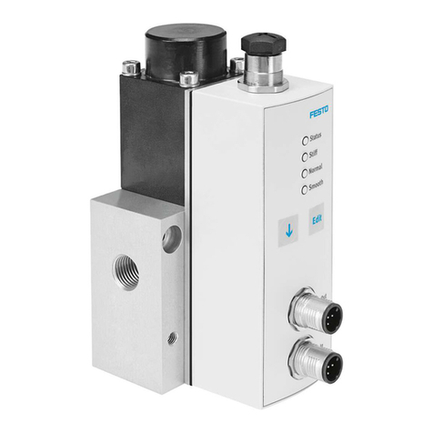
VYKB
Media separated solenoid valve
Festo SE & Co. KG
Ruiter Straße 82
73734 Esslingen
Deutschland
+49 711 347-0
www.festo.com
Operating instructions
8146559
2021-02
[8146561]
Translation of the original instructions
© 2021 all rights reserved to Festo SE & Co. KG
1Applicable documents
Document Product Table of contents
Application note – Constraints for liquid handling, including media
resistance
Tab. 1
All available documents for the product è www.festo.com/sp.
2 Safety
2.1 Safety instructions
2.1.1 General safety instructions
–Only use the product in original status without unauthorised modifications.
–Only use the product if it is in perfect technical condition.
–Do not subject the product to mechanical stress.
–Before working on the product: switch off the power supply and medium supply
and secure it against being switched on again.
–Always grasp the plug by the housing. Do not pull on the cable.
–Comply with the handling specifications for electrostatically sensitive devices.
–The product can become hot during continuous operation, during operation
in block assembly and in the event of individual faults. Provide protective
measures for use and handling of the product.
–Do not operate the product in the vicinity of highly flammable media and
substances.
–Use the product indoors only.
–Use the product only in a dry environment.
–This product can generate high frequency interference, which may make it nec-
essary to implement interference suppression measures in residential areas.
–Do not exceed the maximum permissible pressure of the medium. In doing so,
take potential pressure peaks in the system into account.
2.1.2 Media
–Media may escape in the event of leakage. Take suitable protective measures
for use and handling of the product.
–When using crystallising media, plan appropriate rinsing routines for the
product.
–Use only media that will not cause dangerous reactions if mixed.
–Use only media to which the materials used for the product are resistant.
Materials in contact with the medium è 12 Technical data.
–For evaluation of the media resistance è 1 Applicable documents.
2.1.3 Return to Festo
Hazardous substances can endanger the health and safety of personnel and
cause damage to the environment. To prevent hazards, the product should only be
returned if explicitly requested by Festo.
–Consult your regional Festo contact.
–Complete the declaration of contamination and attach it to the outside of the
packaging.
–Comply with all legal requirements for the handling of hazardous substances
and the transport of dangerous goods.
2.2 Intended use
The solenoid valve VYKB is intended for installation in laboratory devices. The
product is used to control gaseous and liquid media within the limits of the
technical data. The chemical resistance of the materials of the product in contact
with the media must be tested for every application. The user is responsible for
validating the application.
–Operate the product only with a suitable sub-base. Observe the product label-
ling on the sub-base.
2.3 Foreseeable misuse
–Do not bring the product into direct contact with foods or their ingredients.
–Do not use the product for installation in medical devices.
–Do not use the product bidirectionally.
2.4 Training of qualified personnel
Work on the product may only be carried out by qualified personnel who can
evaluate the work and detect dangers. The qualified personnel have skills and
experience in dealing with electrical (open-loop) control technology.
3 Additional information
–Accessories è www.festo.com/catalogue.
4Service
Contact your regional Festo contact person if you have technical questions
è www.festo.com.
5Product overview
5.1 Function
The product is a directly actuated directional control valve with solenoid coil. If
the solenoid coil is supplied with power, the LED on the electrical sub-base lights.
Product Circuit symbol Function
VYKB-...-M22C-... 2/2-way valve, normally closed (2) è (1)
VYKB-...-M32-... 3/2-way valve, normally closed (2) è (1) and opened
(2) è (3)
Tab. 2: Circuit symbols
5.2 Structure
The product is a modular design. The connecting cable, the seal and the sub-base
are available as accessories. The connecting cable and the seal are included in the
scope of delivery.
1
2
3
4
2
1
3
4
Fig. 1: Structure of the product
1Solenoid valve VYKB
2Connecting cable NEBV-HPG2-...
3Seal VAVC-K2-...
4Sub-base VABS-K2-...
6 Transport and Storage
–Store the product in a cool, dry, UV-protected and corrosion-protected environ-
ment. Ensure that storage times are kept to a minimum.
7Assembly
7.1 Valve mounting
Requirements
–The medium lines are unpressurised and do not carry any medium.
–The medium lines are free of particles and fibres.
–The medium line ends are mounted.
–Dirt filters are installed in the medium line upstream from the product. Max.
particle size: 5 µm.
–The power supply is switched off.
Mechanical
• Mount the product with the accompanying screws. Observe the following
tightening torque:
Product Thread size Tightening torque [Nm]
VYKB-F10 M2 0.16 … 0.2
VYKB-F12 M3 0.27 … 0.33
7.2 Mounting of medium connection
• Mount the fittings on the sub-base. Observe the following tightening torque:

Thread size Tightening torque [Nm]
M6, 1/4-28 UNF 1.5 … 1.8
8 Installation
8.1 Fluid installation
1
2
3
4
Fig. 2: Fluid connections
1Channel (1) "NC"
2Channel (2) "COM"
3Only 3/2-way valve: channel (3)
"NO"
4Seal
8.2 Electrical installation
WARNING
Risk of Injury due to Electric Shock.
• For the electric power supply, use only PELV circuits that ensure a reliable
electric disconnection from the mains network.
•Observe IEC 60204-1/EN 60204-1.
• The unit must be powered by a power source that fulfils the requirements of an
energy-limited circuit in accordance with IEC 61010-1/EN 61010-1.
–Note polarity (red cable = +).
–Observe maximum cable length of 10 m.
–Insert the plug.
9Commissioning
Requirements
–The product is fully mounted and connected.
Commissioning the product
1. Switch on the media supply.
2. Switch on the power supply.
3. Check the product for leakage.
10 Maintenance
–Inspect the product regularly from the outside for leakage and function.
–Clean the outside of the product as required with a soft dry cloth.
11 Disassembly
1. Switch off the power supply.
2. Depressurise the valve and medium line and allow them to cool.
3. Drain the medium line and valve completely. Collect the discharged media in a
suitable container.
4. Disassemble the valve. Do not pull on the cable. Unlock the locking lug when
removing the plug.
12 Technical data
VYKB -F10 -F12
Technical data, general
Design Rocker valve with diaphragm seal
Installation location use only indoors
Mounting position any
Degree of protection IP40
Flow direction non-reversible
Information on materials Contains paint-wetting impairment substances1)
Min. grid dimension with
block mounting
[mm] 11 13
Load
Vibration severity level 2 in accordance with IEC 60068
Shock severity level 2 in accordance with IEC 60068
Temperature range
Medium [°C] 0 … 50
Environment [°C] 0 … 50
VYKB -F10 -F12
Storage [°C] −20 … +70
Port
fluidic Flange with additional sub-base VABS; 1/4-28 UNF; M6
Electrical Connecting cable NEBVHPG2-PN0.3NLE2
Technical data, fluidic
Medium –liquid media
–gaseous media
Max. contamination level of
the medium
[µm] 5
Materials in contact with the
medium
PEEK, EPDM, FFKM, FKM PEEK, EPDM
Pressure of medium [MPa] −0.075 … +0.1 −0.075 … +0.3
Flow rate Kv [m³/h] 0.034 0.0558
Internal volume [µl] 35 60
Technical data, electrical
Nominal operating voltage
VYKB-...-5 [V DC] 12 +10 %, −5 %
VYKB-...-1 [V DC] 24 ±10 %
Max. switching frequency [Hz] 2
Duty cycle [%] 100
Overvoltage category II
Contamination level 2 2
Max. power consumption
Inrush current
VYKB-...-5 [W] 3.7 5.2
VYKB-...-1 [W] 3.7 4.5
Holding current [W] 1 1
Inrush current
VYKB-...-5 [mA] 308 433
VYKB-...-1 [mA] 154 188
Holding current
VYKB-...-5 [mA] 83 84
VYKB-...-1 [mA] 42 42
1) PWIS = paint-wetting impairment substances
Tab. 3: Technical data
Type of severity level (SL)
Vibration load
Frequency range [Hz] Acceleration [m/s2]Deflection [mm]
SL1 SL2 SL1 SG2 SL1 SL2
2 … 8 2 … 8 – – ±3.5 ±3.5
8 … 27 8 … 27 10 10 – –
27 … 58 27 … 60 – – ±0.15 ±0.35
58 … 160 60 … 160 20 50 – –
160 … 200 160 … 200 10 10 – –
Shock load
Acceleration [m/s2]Duration [ms] Shocks per direction
SL1 SL2 SL1 SL2 SL1 SL2
±150 ±300 11 11 5 5
Continuous shock load
Acceleration [m/s2]Duration [ms] Shocks per direction
±150 6 1000
Tab. 4: Type of severity level (SL)

This manual suits for next models

2

Other Festo Control Unit manuals

Festo CAMC-G-S3 User manual

Festo

Festo CAMC-G-S3 User manual

Festo MS6N-SV-***-E-ASIS Series User manual

Festo

Festo MS6N-SV-***-E-ASIS Series User manual

Festo CPE Series User manual

Festo

Festo CPE Series User manual

Festo CPX-FB13 Parts list manual

Festo

Festo CPX-FB13 Parts list manual

Festo VOFA-L26-T52-M Series User manual

Festo

Festo VOFA-L26-T52-M Series User manual

Festo CPX-AP-I-8DI-M12-5P Parts list manual

Festo

Festo CPX-AP-I-8DI-M12-5P Parts list manual

Festo VZQA-C-M22C Series Setup guide

Festo

Festo VZQA-C-M22C Series Setup guide

Festo CPX-FVDA-P2 Parts list manual

Festo

Festo CPX-FVDA-P2 Parts list manual

Festo MS6-SV Series User manual

Festo

Festo MS6-SV Series User manual

Festo CPV..-DI01 series User manual

Festo

Festo CPV..-DI01 series User manual

Festo CAMC-G-S3 User manual

Festo

Festo CAMC-G-S3 User manual

Festo ERMB Series User manual

Festo

Festo ERMB Series User manual

Festo ERMB User manual

Festo

Festo ERMB User manual

Festo CPX-FB14 Parts list manual

Festo

Festo CPX-FB14 Parts list manual

Festo CPX-FVDA-P2 User manual

Festo

Festo CPX-FVDA-P2 User manual

Festo MH1 Series Parts list manual

Festo

Festo MH1 Series Parts list manual

Festo MS6(N)-SV-...-C User manual

Festo

Festo MS6(N)-SV-...-C User manual

Festo CP-FB8-E Parts list manual

Festo

Festo CP-FB8-E Parts list manual

Festo VZXA-C/W-M-V4 Series User manual

Festo

Festo VZXA-C/W-M-V4 Series User manual

Festo DSM Series User manual

Festo

Festo DSM Series User manual

Festo VZWP-L-M22C Series User manual

Festo

Festo VZWP-L-M22C Series User manual

Festo JMFH...D...C-EX Series Use and care manual

Festo

Festo JMFH...D...C-EX Series Use and care manual

Festo CPX-E- AO-U-I Series User manual

Festo

Festo CPX-E- AO-U-I Series User manual

Festo VZBA-...-63-T-22-...-V4V4T series User manual

Festo

Festo VZBA-...-63-T-22-...-V4V4T series User manual

Popular Control Unit manuals by other brands

Rockwell Automation ControlLogix 1756 Series Selection guide

Rockwell Automation

Rockwell Automation ControlLogix 1756 Series Selection guide

Allen-Bradley MicroLogix 1200 installation instructions

Allen-Bradley

Allen-Bradley MicroLogix 1200 installation instructions

SMC Networks VZ400 Series quick start guide

SMC Networks

SMC Networks VZ400 Series quick start guide

LEGRAND IC5010 Instruction/installation sheet

LEGRAND

LEGRAND IC5010 Instruction/installation sheet

Viola Systems ESERV-10 user manual

Viola Systems

Viola Systems ESERV-10 user manual

National Instruments FieldPoint FP-1001 user manual

National Instruments

National Instruments FieldPoint FP-1001 user manual

swissflex uni_75RF operating instructions

swissflex

swissflex uni_75RF operating instructions

Aventics TC08 Operation/Assembly/Exchange/Expansion

Aventics

Aventics TC08 Operation/Assembly/Exchange/Expansion

Beckhoff EP5 Series Documentation

Beckhoff

Beckhoff EP5 Series Documentation

Tanda TX7230 Installation and operation manual

Tanda

Tanda TX7230 Installation and operation manual

Metso Full Bore Fire-Tite 9REL Series Installation maintenance and operating instructions

Metso

Metso Full Bore Fire-Tite 9REL Series Installation maintenance and operating instructions

Dynamic DX-REMG91 installation manual

Dynamic

Dynamic DX-REMG91 installation manual

Growatt ShineWiFi-X Configuration guide

Growatt

Growatt ShineWiFi-X Configuration guide

Samsung SPC-6000 user manual

Samsung

Samsung SPC-6000 user manual

Vimar Elvox 6153/682 Installer's guide

Vimar

Vimar Elvox 6153/682 Installer's guide

IRT CP Installation, operation & maintenance manual

IRT

IRT CP Installation, operation & maintenance manual

Mirabelle MIRRI9009CP manual

Mirabelle

Mirabelle MIRRI9009CP manual

Globalstar ST150M user manual

Globalstar

Globalstar ST150M user manual

manuals.online logo
manuals.online logoBrands
  • About & Mission
  • Contact us
  • Privacy Policy
  • Terms and Conditions

Copyright 2025 Manuals.Online. All Rights Reserved.