manuals.online logo
Brands
  1. Home
  2. •
  3. Brands
  4. •
  5. Festo
  6. •
  7. Controllers
  8. •
  9. Festo VEAB User manual

Festo VEAB User manual

Translation of the original instructions
1 Further applicable documents
All available documents for the product èwww.festo.com/pk.
User documentation
Name, type Table of contents
H-rail mounting, VAME-P7-T Assembly instructions
Mounting plate, VAME-P...-Y Assembly instructions
Manifold rail, VABM-P6-15.../-P7-18... Assembly instructions
Tab. 1 Documentation on the product
2 Safety
2.1 Safety instructions
– Only use the product in original status without unauthorised modifications.
– Only use the product if it is in perfect technical condition.
– Take into consideration the ambient conditions at the location of use.
– Prior to mounting, installation and maintenance work: Switch off power sup-
ply and secure it from being switched back on.
2.2 Intended use
The proportional-pressure regulator is intended to regulate a pressure propor-
tional to a specified setpoint value.
The product is intended for use in industrial environments.
2.3 Training of skilled personnel
Installation, commissioning, maintenance and disassembly should only be con-
ducted by qualified personnel.
The specialized personnel must be familiar with the installation and operation of
electrical and pneumatic control systems.
3 Further information
– Accessories èwww.festo.com/catalogue.
4 Service
Contact your regional Festo contact person if you have technical questions
èwww.festo.com.
5 Product overview
5.1 Functional principle
A built-in pressure sensor records the pressure at the working port and compares
this value with the setpoint value. In the event of deviations between the setpoint
value and actual value, the valve regulates until the outlet pressure has reached
the setpoint value.
Fig. 1 Pneumatic circuit symbol
5.2 Configuration
5.2.1 Product design
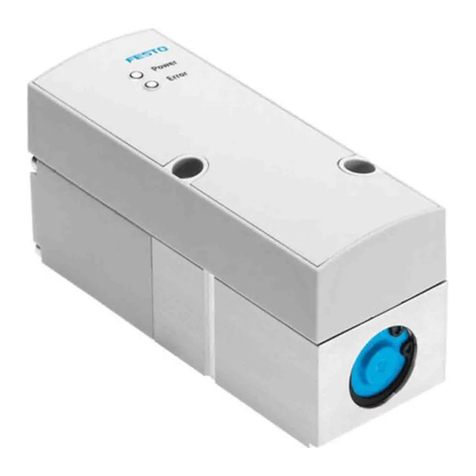
In-line valve
1LED
2M8 plug
3Air connection (2)
Fig. 2 Front view
1Compressed air connection (1)
2Exhaust air connection (3)
3Through-holes for fastening the
valve
Fig. 3 Rear view
Sub-base valve
1LED
2Electrical connection, M8 plug
3Through-holes (2x) for fastening
the valve to the sub-base
Fig. 4 Front view
1Air connection (2)
2Exhaust air connection (3)
3Compressed air connection (1)
Fig. 5 Bottom view
8080725
VEAB
Proportional-pressure regulator
8080725
2018-05a
[8080669]
Instructions|Assembly, Installation, Operating
Festo AG & Co. KG
Ruiter Straße 82
73734 Esslingen
Germany
+49 711 347-0
www.festo.com
5.2.2 Product variants
Characteristic Type code Description
Basic function VEAB Piezo proportional-pressure
regulator
L In-line valveValve type
B Sub-base valve
Valve function 26 2x 3/2-way valve, normally
closed
D2 0…2bar
D7 0…1bar
D9 0…6bar
D12 0…0.2bar
D13 –1…1bar
D14 –1…0bar
D15 –0.5…0.5bar
Pressure range
D18 –1…5bar
F Flange/sub-basePneumatic connection
Q4 Push-in connector 4mm
V1 Voltage variant 0…10VSetpoint value input and actual
value output A4 Current variant 4…20mA
Nominal operating voltage 1 24VDC
Electrical connection R1 Plug M8, 4-pin
Tab. 2 Product variants
6 Transport and storage
– Store the product in a dry, UV- and corrosion-protected environment.
– Ensure short storage times.
7 Mechanical installation
1. Make sure there is sufficient space for the connecting cable and tubing con-
nections.
ÄIn this way you will prevent the connecting lines and the tubes from kink-
ing.
2. Place the valve as close to the consumer as possible.
ÄThis leads to improved control precision and shorter response times.
Mounting options of the valve:
– Through-hold mounting of the in-line valve through 3lateral through-holes
– Mounting of the in-line valve to H-rails using H-rail mounting VAME-P7-T
è 1 Further applicable documents
– Mounting of the in-line valve to the mounting plate VAME-P7-Y
è 1 Further applicable documents
– Mounting of the sub-base valve using 2through holes using the sub-base
VABM-.... è 1 Further applicable documents
8 Installation
8.1 Pneumatic installation (in-line valve)
Valves for standard operation (overpressure)
1. Attach tubing to the following connections:
– Compressed air connection (1) è Fig.3
– Air connection (2) è Fig.2
2. Mount a silencer to the exhaust port (3) or remove the exhaust air with ducts
è Fig.3.
Valves for vacuum operation (reversible operation)
1. Attach tubing to the following connections:
– Vacuum connection (3) è Fig.3
– Air connection (2) è Fig.2
2. Mount silencer to the compressed air connection (1), to protect the valve from
coarse dirt particles è Fig.2.
Operating medium
NOTICE!
Pay attention to compressed air quality.
Damage to property or loss of function from lubricated compressed air.
• Operate product only with unlubricated compressed air.
• Observe the requirements for compressed air quality èTechnical data.
8.2 Electrical installation
WARNING!
Risk of injury due to electric shock.
• For the electric power supply, use only PELV circuits that ensure a reliable
electric disconnection from the mains network.
• Observe IEC60204-1/EN60204-1.
1. If a screened cable is used: earth the shield at the cable end farther away
from the valve.
2. Install electrical connecting cable without squeezing, kinking or stretching.
3. Screw electrical connecting cable onto the M8 plug connector. Tightening
torque maximum 0.3Nm
Connection Pin Allocation Wire colour1)
(NEBU-M8...)
1 + 24V DC BN
2 Setpoint value (+) WH
3 GND BU
4 Actual value (+) BK
1) in accordance with IEC 757
Tab. 3 Pin allocation for plug M8, 4-pin
9 Commissioning
1. Check the operating conditions and limit values èTechnical data.
2. Switch on compressed air supply.
3. Check pneumatic connection points for tightness.
4. Connect valve to a setpoint signal.
5. Switch on operating voltage.
10 Cleaning
1. Switch off the following energy sources to clean the outside:
– Compressed air
– Operating voltage
2. Clean the outside of the product with a soft cloth. Do not use aggressive
cleaning agents.
11 Malfunctions
11.1 Diagnostics
LED
indicator
Status and meaning
LED illuminates green:
– Operating voltage is present and within the permissible range.
– No error is present.
– Setpoint signal lies in the permissible range (0…10.8V or 2.5…20.5mA).
LED flashes red:
–Operating voltage lies above the permissible range (>29V).
LED flashes alternately red and green:
–Setpoint signal lies above the permissible range (>10.8V or >20.5mA).
–Setpoint signal lies below the permissible range (<2.5mA).
LED is off:
– No operating voltage applied.
–Operating voltage lies below the permissible range (<19V).
Tab. 4 LED
11.2 Fault clearance
Fault description Cause Remedy
Operating voltage not applied Check operating voltage con-
nection.
No setpoint voltage Check controller and connec-
tion.
Valve does not react.
Compressed air supply not
present/insufficient
Check compressed air supply.
Flow rate is too low. Restriction of the flow cross
section due to connection tech-
nology (swivel fittings).
Use alternative connection
technology.
Pressure remains constant des-
pite modified setpoint specific-
ation.
Supply cable breakage; the last
outlet pressure set is main-
tained but not regulated. Slow
pressure drop due to leakage.
Replace supply cable.
Setpoint value is not reached. Inlet pressure p1 is too low. Increase inlet pressure p1.
Maintain permissible maximum
operating pressure
è 14 Technical data.
Tab. 5
12 Dismounting
1. Switch off setpoint voltage.
2. Switch off operating voltage.
3. Switch off compressed air supply.
4. Remove electrical connecting cables.
5. Remove compressed air lines.
6. Dismantle the product.
13 Disposal
ENVIRONMENT!
Send the packaging and product for environmentally sound recycling in accord-
ance with the current regulations èwww.festo.com/sp.
14 Technical data
Characteristic Specification/value
Design Proportional-pressure regulator
Mounting position Any
Compressed air in accordance with
ISO 8573-1:2010 [7:4:4]
Operating medium
Inert gases
Information on the operating
medium
Lubricated operation not possible
CE marking
(Declaration of conformity
èwww.festo.com/sp)
In accordance with EU-EMC Directive1)
Degree of protection IP65 (completely mounted)
Climate class in accordance
with EN60721
3K3
Nominal operating voltage [VDC] 24
Operating voltage range [VDC] 19…29
Permissible residual ripple of
operating voltage
[%] 10
Maximum current consump-
tion
[A] 0.08
Maximum signal line length [m] <30
Inlet pressure 1 (vacuum in connection 3)
VEAB-...-D13-... [bar] 0…2
VEAB-...-D14-... [bar] –1
VEAB-...-D15-... [bar] 0…2bar
VEAB-...-D18-... [bar] 0…5.5
Inlet pressure 1 in connection 1
VEAB-...-D2-... [bar] 0…4
VEAB-...-D7-... [bar] 0…3
VEAB-...-D9-... [bar] 0…6.5
VEAB-...-D12-... [bar] 0…1
Pressure control range
VEAB-...-D2-... [bar] 0.01…2
VEAB-...-D7-... [bar] 0.005…1
VEAB-...-D9-... [bar] 0.03…6
VEAB-...-D12-... [bar] 0.001…0.2
VEAB-...-D13-... [bar] –1…+1
VEAB-...-D14-... [bar] –1…–0.005
VEAB-...-D15-... [bar] –0.5…+0.5
VEAB-...-D18-... [bar] –1…+5
Accuracies
Repetition accuracy [%] ±0.4FS (full scale)
Hysteresis
VEAB-...-D2-...
VEAB-...-D7-...
VEAB-...-D9-...
VEAB-...-D14-...
[%] £0.25FS (full scale)
Hysteresis
VEAB-...-D12-...
VEAB-...-D13-...
VEAB-...-D15-...
VEAB-...-D18-...
[%] £0.5
Linearity error
VEAB-...-D2-...
VEAB-...-D7-...
VEAB-...-D9-...
VEAB-...-D14-...
[%] £0.5FS (full scale)
Linearity error
VEAB-...-D12-...
VEAB-...-D13-...
VEAB-...-D15-...
VEAB-...-D18-...
[%] £0.8FS (full scale)
Analogue output [%] 2FS (full scale)
Permissible temperature range
Environment [°C] 0…+50
Medium [°C] +5…+50 (non-condensing)
Storage [°C] –20…+70
Setpoint value
Analogue input (current vari-
ant)
[mA] 4…20
Analogue input (voltage vari-
ant)
[V] 0…10
Characteristic Specification/value
Input resistance setpoint value
At 4…20mA [Ω] 250
At 0…10V [kW]10
Actual value
Analogue output (current
variant)
[mA] 4…20
Analogue output (voltage
variant)
[V] 0…10
Resistance to vibration/shock resistance (in accordance with IEC 60068)
Information Explanation of the severity levels (SL)
è Tab. 7 Features of severity level (SL)
Vibration (part 2 – 6)
Mounting via through-holes SL2
Mounting to H-rail, mounting
plate, manifold rail
SL1
Shock (part 2 – 27)
Mounting via through-holes SL2
Mounting to H-rail, mounting
plate, manifold rail
SL1
Continuous shock (part 2 – 27)
Mounting via through-holes SL1
Mounting to H-rail, mounting
plate, manifold rail
SL1
Materials
Housing PA, PAMX
Screws Steel, hardened and tempered
Steel, galvanised
Seals NBR
Adapter plate Wrought aluminium alloy
Weight
Sub-base valve weight [g] Approx. 70
In-line valve weight [g] Approx. 70
1) The product is intended for industrial use. Outside of industrial environments, e.g.in commercial and
mixed-residential areas, actions to suppress interference may have to be taken.
Tab. 6 General technical data
Features of severity level (SL)
Vibration load
Frequency range [Hz] Acceleration [m/s2] Deflection [mm]
SL1 SL2 SL1 SL2 SL1 SL2
2…8 2…8 – – ±3.5 ±3.5
8…27 8…27 10 10 – –
27…58 27…60 – – ±0.15 ±0.35
58…160 60…160 20 50 – –
160…200 160…200 10 10 – –
Shock load
Acceleration [m/s2] Duration [ms] Shocks per direction
SL1 SL2 SL1 SL2 SL1 SL2
±150 ±300 11 11 5 5
Continuous shock load
Acceleration [m/s2] Duration [ms] Shocks per direction
±150 6 1000
Tab. 7 Features of severity level (SL)

Other Festo Controllers manuals

Festo VPPE F1A Series User manual

Festo

Festo VPPE F1A Series User manual

Festo SPC200 Series User manual

Festo

Festo SPC200 Series User manual

Festo VPPM Series User manual

Festo

Festo VPPM Series User manual

Festo CMMP-AS User manual

Festo

Festo CMMP-AS User manual

Festo DFPD-Series User manual

Festo

Festo DFPD-Series User manual

Festo CMMP-AS-***-M3 Series User manual

Festo

Festo CMMP-AS-***-M3 Series User manual

Festo CMMS-AS Series Operating and installation instructions

Festo

Festo CMMS-AS Series Operating and installation instructions

Festo DGSL E Series User manual

Festo

Festo DGSL E Series User manual

Festo CMXR-C1 Installation manual

Festo

Festo CMXR-C1 Installation manual

Festo DRD Series User manual

Festo

Festo DRD Series User manual

Festo EasyPort USB D16A User manual

Festo

Festo EasyPort USB D16A User manual

Festo CMMS-ST-C8-7-G2 User manual

Festo

Festo CMMS-ST-C8-7-G2 User manual

Festo MPPES 010 Series User manual

Festo

Festo MPPES 010 Series User manual

Festo SLS-6-Series-P-A User manual

Festo

Festo SLS-6-Series-P-A User manual

Festo CPX-E-CEC Series User manual

Festo

Festo CPX-E-CEC Series User manual

Festo DFPD-Series User manual

Festo

Festo DFPD-Series User manual

Festo CMMP-AS Series Reference guide

Festo

Festo CMMP-AS Series Reference guide

Festo CMMP-AS-***-M3 Series Operating and installation instructions

Festo

Festo CMMP-AS-***-M3 Series Operating and installation instructions

Festo MPAL-VI User manual

Festo

Festo MPAL-VI User manual

Festo CMMP-AS-C2-3A User manual

Festo

Festo CMMP-AS-C2-3A User manual

Festo CMXH User manual

Festo

Festo CMXH User manual

Festo EGSP Series User manual

Festo

Festo EGSP Series User manual

Festo LFR-B Series User manual

Festo

Festo LFR-B Series User manual

Festo CPX-CMAX Operating and installation instructions

Festo

Festo CPX-CMAX Operating and installation instructions

Popular Controllers manuals by other brands

Enttec Open DMX Ethernet user manual

Enttec

Enttec Open DMX Ethernet user manual

Burkert 6626 TwinPower operating instructions

Burkert

Burkert 6626 TwinPower operating instructions

Siemens SIMATIC S7 System manual

Siemens

Siemens SIMATIC S7 System manual

ComAp InteliLite NT MRS reference guide

ComAp

ComAp InteliLite NT MRS reference guide

Gemo DT109PX Installation & use

Gemo

Gemo DT109PX Installation & use

Sun Microsystems Sun StorEdge D1000 Upgrade Installation Guide

Sun Microsystems

Sun Microsystems Sun StorEdge D1000 Upgrade Installation Guide

FIBER SENSYS Fiber Defender FD508 user manual

FIBER SENSYS

FIBER SENSYS Fiber Defender FD508 user manual

Leviton FEBC Operation manual

Leviton

Leviton FEBC Operation manual

tbs electronics Omnicharge Solar OCS 150-60 owner's manual

tbs electronics

tbs electronics Omnicharge Solar OCS 150-60 owner's manual

Maguire Products GRAVIMETRIC AUGER FEEDER MGF-ST instruction manual

Maguire Products

Maguire Products GRAVIMETRIC AUGER FEEDER MGF-ST instruction manual

Wilo HiControl 1 Installation and operating instructions

Wilo

Wilo HiControl 1 Installation and operating instructions

Parker 514C product manual

Parker

Parker 514C product manual

IWAKI AMERICA WCT900 instruction manual

IWAKI AMERICA

IWAKI AMERICA WCT900 instruction manual

Turnigy Fatboy 300A ESC Manuals

Turnigy

Turnigy Fatboy 300A ESC Manuals

LEYBOLD DISPLAY TWO instruction manual

LEYBOLD

LEYBOLD DISPLAY TWO instruction manual

VERDER Carbolite Gero Chessell 6100A Installation, operation and maintenance instructions

VERDER

VERDER Carbolite Gero Chessell 6100A Installation, operation and maintenance instructions

Carrier KJR-12B/DP-E owner's manual

Carrier

Carrier KJR-12B/DP-E owner's manual

Hach sc200 user manual

Hach

Hach sc200 user manual

manuals.online logo
manuals.online logoBrands
  • About & Mission
  • Contact us
  • Privacy Policy
  • Terms and Conditions

Copyright 2025 Manuals.Online. All Rights Reserved.