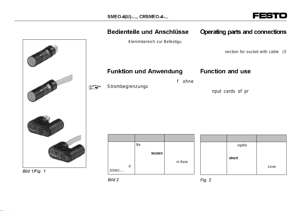
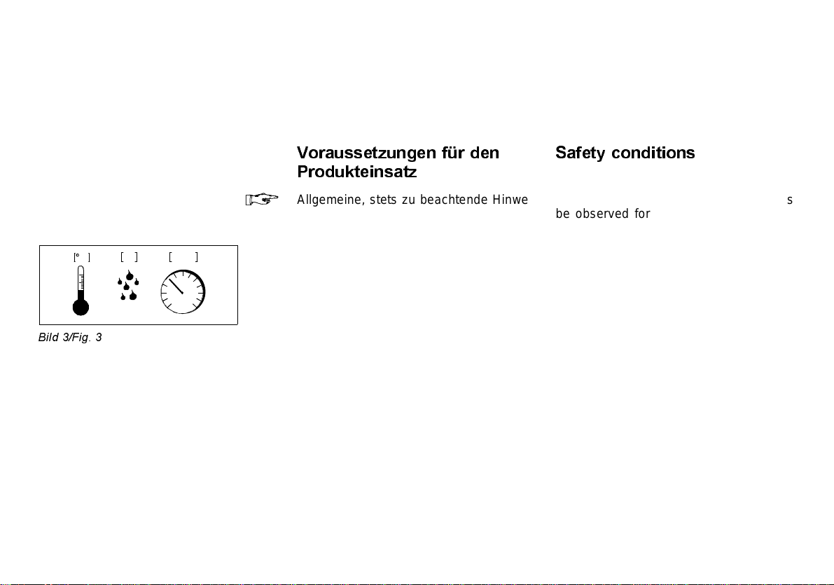
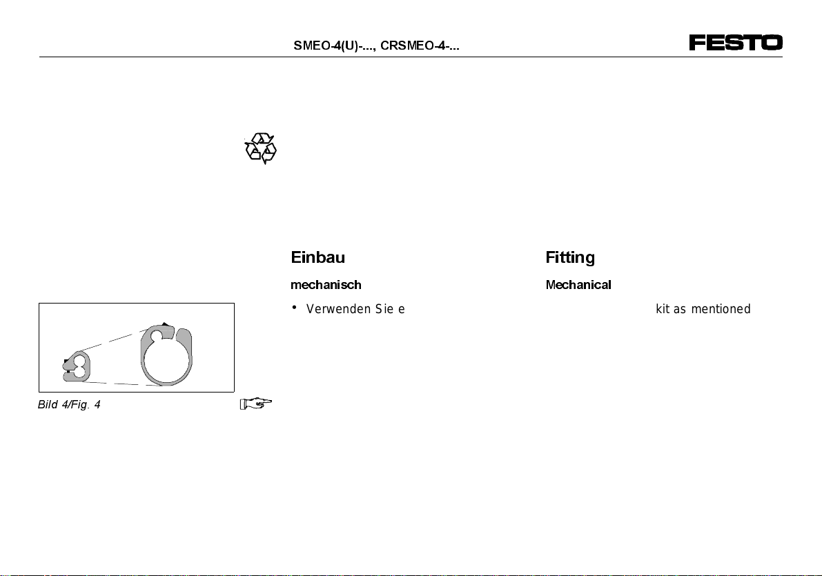
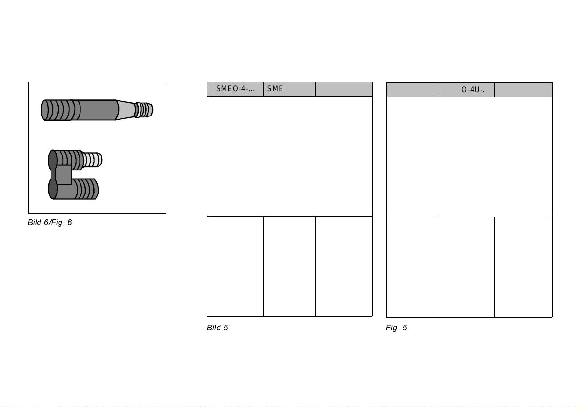
Festo SMEO-4 Series User manual
Other Festo Switch manuals

Festo
Festo VPEV-1/8-M12 User manual

Festo
Festo SMTO-4 Series User manual

Festo
Festo SME-1 Series User manual

Festo
Festo SRBF-C series User manual

Festo
Festo EAPM-L5-70-SLM User manual

Festo
Festo SMT-CDC-PS-24V-SQM8 User manual

Festo
Festo VABF-S4-A2G2 Series User manual

Festo
Festo SME-8-K-...-LED-24 Series User manual

Festo
Festo SME-1-B User manual

Festo
Festo PENV O-S-L-GH Series User manual

Festo
Festo VPEV-1/8 User manual

Festo
Festo SME-8-ZS-230V-...-OE Series User manual

Festo
Festo SRBE EX Series User manual

Festo
Festo SRBE C1 Series User manual

Festo
Festo CAMC-G-S Series User manual

Festo
Festo SME-8 Series User manual

Festo
Festo VPEV-W-***-LED-GH Series User manual

Festo
Festo SMTO-1 C Series User manual

Festo
Festo PE-PK Series User manual

Festo
Festo PEV-1/4-B User manual