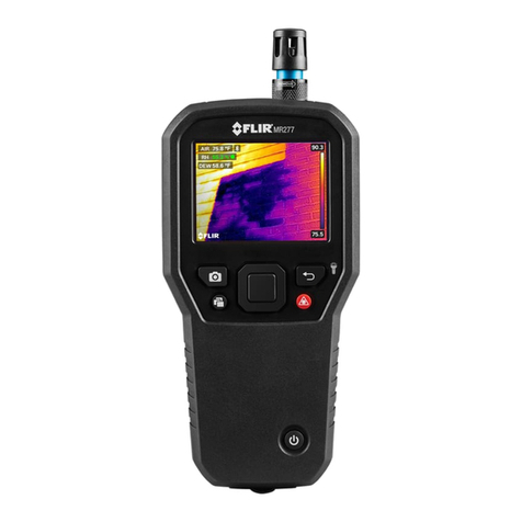
FLIR MSX MR277 User manual

USER MANUAL
Moisture Meter,
MSX® IR Camera,
Hygrometer
Model MR277
Distributed by:
Reduction Revolution Pty Ltd
www.reductionrevolution.com.au/FLIR


USER MANUAL
Moisture Meter, MSX® IR
Camera, Hygrometer
#NAS100005; r. AL/76939/76957; en-US iii


Table of contents
1 Advisories ..........................................................................1
1.1 Copyright..................................................................1
1.2 Quality Assurance ...................................................... 1
1.3 Documentation ..........................................................1
1.4 Disposal of Electronic Waste.........................................1
2 Introduction........................................................................2
3 Safety ................................................................................4
3.1 Safety Warnings and Cautions.......................................4
4 Descriptions .......................................................................5
4.1 Product Description.....................................................5
4.2 Control Button Descriptions ..........................................6
4.3 Display Description ..................................................... 6
4.4 Sensor Extension Accessory (MR-EXT) .......................... 7
5 User Interface Menus...........................................................8
5.1 Menu Structure Overview ............................................. 8
5.2 Main Menu Icons ........................................................8
5.3 Temperature Scale Menu ............................................. 9
5.4 Image Mode Menu.................................................... 10
5.5 Measurement Menu .................................................. 13
5.6 Moisture Modes Menu ............................................... 15
5.7 Color Menu ............................................................. 18
5.8 Settings Menu.......................................................... 19
6 Powering the MR277 .......................................................... 27
7 Moisture Measurement Operation ....................................... 28
7.1 Moisture Measurements Basics ................................... 28
7.2 Moisture Display Options............................................ 29
7.3 IGM™ Moisture and IGM™ Custom Modes.................... 32
7.4 Moisture Measurement Modes .................................... 33
7.5 Pinless Moisture Measurements .................................. 36
7.6 Pin Probe Measurements ........................................... 36
7.7 MR12 Ball Moisture Probe (Optional) ............................ 37
7.8 Set Reference Mode ................................................. 37
7.9 High Moisture Alarm.................................................. 38
8 Thermal and Visible Camera Operation ................................ 40
8.1 Thermal Camera ...................................................... 40
8.2 Automatic/Lock Temperature Scaling ............................ 42
#NAS100005; r. AL/76939/76957; en-US v

Table of contents
8.3 Digital (Visible) Camera ............................................. 43
8.4 High/Low IR Temperature Alarms ................................. 44
9 Ambient Temperature and Humidity Measurements .............. 45
9.1 Temperature & RH Measurements and Dew Point,
Vapor Pressure, and Mixing Ratio Calculations ............... 45
9.2 Progressive Environmental Stability Indicator for RH
%.......................................................................... 46
10 Capturing and Working with Screen Captures....................... 47
10.1 Capturing Images ..................................................... 47
10.2 Viewing Images on the MR277 .................................... 47
10.3 Deleting images ....................................................... 47
10.4 Transferring Images via PC Interface............................. 47
10.5 Transmitting Images and Data via Bluetooth®................. 48
11 Bluetooth® Communication and FLIR Tools™ Mobile
App ................................................................................. 49
11.1 FCC Compliance ...................................................... 49
12 Field Firmware Updates ..................................................... 51
12.1 System Firmware Update ........................................... 51
13 Maintenance..................................................................... 52
13.1 Cleaning................................................................. 52
13.2 Battery Service ........................................................ 52
13.3 Disposal of Electronic Waste....................................... 52
13.4 MR277 Crash Recovery ............................................. 52
14 Specifications................................................................... 53
14.1 General Specifications............................................... 53
14.2 Imaging Specifications............................................... 53
14.3 Moisture Meter Specifications ..................................... 54
14.4 Visible Spectrum Camera Specifications........................ 54
14.5 Safety Specifications ................................................. 55
14.6 MR13 Sensor Measurement and Calculation
Specifications .......................................................... 55
15 Appendices ...................................................................... 56
15.1 Material Groups ....................................................... 56
15.1.1 Common names of timbers .............................. 56
15.1.2 Botanical names of timbers .............................. 59
15.2 %WME Table (% Wood Moisture Equivalent) .................. 63
#NAS100005; r. AL/76939/76957; en-US vi
Advisories
1
1.1 Copyright
©2020 FLIR Systems, Inc. All rights reserved worldwide.
No parts of the software including source code may be reproduced, transmit-
ted, transcribed or translated into any language or computer language in any
form or by any means, electronic, magnetic, optical, manual or otherwise,
without the prior written permission of FLIR Systems.
The documentation must not, in whole or part, be copied, photocopied, repro-
duced, translated or transmitted to any electronic medium or machine-read-
able form without prior consent, in writing, from FLIR Systems. Names and
marks appearing on the products herein are either registered trademarks or
trademarks of FLIR Systems and/or its subsidiaries. All other trademarks,
trade names or company names referenced herein are used for identification
only and are the property of their respective owners.
1.2 Quality Assurance
The Quality Management System under which these products are developed
and manufactured has been certified in accordance with the ISO 9001 stand-
ard. FLIR Systems is committed to a policy of continuous development; there-
fore, we reserve the right to make changes and improvements on any of the
products without prior notice.
1.3 Documentation
To access the latest manuals and notifications, go to the Download tab at:
https://support.flir.com. It only takes a few minutes to register online. In the
download area you will also find the latest releases of manuals for our other
products, as well as manuals for our historical and obsolete products.
1.4 Disposal of Electronic Waste
As with most electronic products, this equipment must be disposed
of in an environmentally friendly way, and in accordance with existing
regulations for electronic waste. Please contact your FLIR Systems
representative for more details.
#NAS100005; r. AL/76939/76957; en-US 1

Introduction
2
Thank you for selecting the FLIR MR277. The MR277 integrates high quality
thermal imaging and digital camera technology with best-in-class moisture
detection and measurement. The MR277 includes an integrated noninvasive
pinless moisture sensor, an external pin moisture probe (MR02), a replace-
able temperature and relative humidity ambient sensor (MR13), and a sensor
extender (MR-EXT). The MR277 also provides dew point, vapor pressure,
and mixing ratio calculations.
The MR277 features Infrared Guided Measurement (IGM™) technology that
allows you to quickly scan and target problem areas. The MSX® feature (Mul-
ti-Spectral Dynamic Imaging) superimposes the digital camera image on the
thermal image providing valuable image detail.
The MR277 stores camera images (with measurement data) for later transfer
to a PC (via USB). Images can also be transmitted to mobile devices using
the Bluetooth® utility running the FLIR Tools™ App.
Visit https://www.support.flir.com to find additional accessories and to register
the MR277 which extends the standard one-year warranty to the 2-10 Year
Warranty.
Features
• FLIR Lepton® microbolometer Focal Plane Array (FPA) with integrated
shutter delivers best-in-class thermal imaging
• Quickly scan for moisture using the integrated noninvasive pinless mois-
ture sensor
• External pin probe (included) for resistive moisture content measurements
• Ambient air temperature and relative humidity readings from field replace-
able sensor
• Sensor extender accessory (MR-EXT) protects sensor from overheating
• IGM™ Moisture mode shows both the thermal image and moisture read-
ings on one screen
• IGM™ Custom mode allows user to select which moisture and psychro-
metric readings to display
• MSX® feature superimposes the digital camera image on the thermal
image
• Psychrometric mode displays ambient air temperature, relative humidity,
dew point, mixing ratio, and vapor pressure
#NAS100005; r. AL/76939/76957; en-US 2

Introduction
2
• Moisture-only mode shows Pin or Pinless moisture readings in large-digit
format
• Temperature Scale Lock adds precision to thermal image scanning
• Easily capture, view, download (to PC), send to mobile devices, and delete
camera images
• Selectable material groups allow you to fine tune pin-based measurements
• Programmable high moisture alarm and high/low temperature alarm with
audible and color-coded display alerts
• Laser pointer and display cross hairs for enhanced targeting
• Easy to read, color display with intuitive graphical interface and tool tips in
local languages
• Internal rechargeable battery via USB connection to AC charger
#NAS100005; r. AL/76939/76957; en-US 3

Safety
3
3.1 Safety Warnings and Cautions
WARNING
Before operating this device, please read, understand, and follow all operational instruc-
tions and safety warnings.
CAUTION
Use of controls or adjustments or performance of procedures other than those specified
herein may result in hazardous radiation exposure.
CAUTION
Use extreme caution when the Laser pointer is on.
CAUTION
Do not point the Laser beam toward anyone's eye or allow the beam to strike the eye from
a reflective surface.
CAUTION
Do not use the Laser near explosive gases or in other potentially explosive areas.
CAUTION
Refer to the CAUTION statement label (shown below) for critical Laser safety information.
#NAS100005; r. AL/76939/76957; en-US 4

Descriptions
4
4.1 Product Description
Figure 4.1 Front, Back, and Bottom Product Description
1. Temperature and Relative Humidity Sensor (MR13)
2. Color Graphical Display
3. Image Capture button
4. Image Gallery button
5. Select button (center). Press to open Menu
6. Power button
7. Laser Pointer button
8. Return and Worklight button
9. Navigation buttons (UP, DOWN, LEFT, RIGHT)
10. Worklight lens
11. Digital camera lens
12. Pinless moisture sensor pad
13. Serial number label
14. Thermal camera lens
15. Laser pointer lens
16. External probe and USB jack compartment
17. External moisture probe RJ jack
18. Battery charging LED
19. USB jack for connecting to PC or AC Charger
#NAS100005; r. AL/76939/76957; en-US 5

Descriptions
4
4.2 Control Button Descriptions
Long press to power ON or OFF.
Return button. Short press to back out to previous screen in Menu
system.
Long press to switch Worklight ON or OFF.
Press the Select button (center) to access the Main Menu and to select
items in the menu system.
Use the outer navigation (ring) buttons to move Up-Down-Left-Right.
Press to switch the Laser pointer ON.
Press to capture screen image.
Press to open image gallery.
4.3 Display Description
Figure 4.2 MR277 Select Display Descriptions
1. Moisture reading
2. Temperature of targeted center spot (cross hairs)
3. Air temperature (from probe measurement)
4. Relative humidity (from probe measurement)
5. Dew point temperature calculation
6. Vapor Pressure calculation in kilo-Pascals (kPa)
#NAS100005; r. AL/76939/76957; en-US 6

Descriptions
4
7. Mixing ratio calculation in grains per pound (GPP)
8. IR Thermal image
9. Cross-hairs (Center Spot)
10. Low end of IR image temperature range
11. High end of IR image temperature range
12. Temperature scale
13. Laser pointer active icon
14. Lamp icon appears when worklight is ON
15. USB icon appears when connected to PC or charger
16. Bluetooth® active icon
NOTE
Not all icons are represented in Figure 4–2. Other available icons are explained in their re-
spective sections of this user manual.
4.4 Sensor Extension Accessory (MR-EXT)
The MR-EXT sensor extender accessory helps protect the RH/Temperature
sensor from overheating by adding a 7.62 cm (3 inch) buffer between the me-
ter and sensor.
The MR-EXT attaches directly to the meter (where the sensor is normally at-
tached) and the sensor attaches to the other end of the extender. Refer to the
illustration below.
Figure 4.3 MR-EXT Extender Accessory
1. Extender socket: plugs into MR277.
2. Extender locking collar.
3. Turn with the arrow icon to loosen collar.
4. Alignment notch for keyed sensor socket.
5. Keyed sensor socket.
6. Sensor socket top view.
#NAS100005; r. AL/76939/76957; en-US 7

User Interface Menus
5
5.1 Menu Structure Overview
When the Select button is pressed, six menu icons appear along the bot-
tom of the MR277 display. Use the left/right navigation buttons to move to a
menu icon, and use the Select button to open a selected menu. Once a menu
is opened, the navigation and Select buttons are used to select modes of op-
erations and settings. Use the Return button to back out of a menu.
5.2 Main Menu Icons
From left to right, the six main menu icons are listed below and shown in Fig-
ure 5–1. Each menu is described in detail in the next sections.
Figure 5.1 Main Menu icons at bottom of display. Press Select to reveal an icon’s sub-menu.
1. Temperature scale
2. Image modes
3. Measurement modes
4. Moisture modes
5. Color (palette) choices
6. Settings menu
#NAS100005; r. AL/76939/76957; en-US 8

User Interface Menus
5
5.3 Temperature Scale Menu
Figure 5.2 Accessing the Temperature Scale Menu
Figure 5.3 Selecting AUTO or LOCK Scaling
The Temperature scale menu allows you to select Automatic (Auto) or Lock
scaling. Use the navigation buttons to move to the desired setting and then
press Select to confirm.
In Automatic mode, the MR277 automatically selects the temperature range
for each thermal image, based on the highest and lowest temperatures de-
tected. In Lock mode, you can ‘lock in’ a particular thermal image’s tempera-
ture range and use this locked range for subsequent thermal image
comparisons. This locked range does not change, regardless of the highest
and lowest temperatures detected for the subsequent images. See Section
8–2 Automatic and Lock Scaling for more information.
To release the Lock mode, simply select the Auto mode as described above.
#NAS100005; r. AL/76939/76957; en-US 9

User Interface Menus
5
5.4 Image Mode Menu
Figure 5.4 Image Mode Menu icon
The Image Mode Menu offers six sub-menus as described below.
•Alignment Distance control: This control allows you to adjust the super-
imposition of the visible image over the thermal image. This is the MSX®
feature. Press Select on the Alignment Distance menu to open it, and
then use the navigation buttons to adjust the alignment. Press Select to
confirm the change.
Figure 5.5 Alignment Distance Control screens
#NAS100005; r. AL/76939/76957; en-US 10

User Interface Menus
5
•Thermal MSX® mode: Select this mode to see the digital camera image
superimposed over the thermal camera image.
Figure 5.6 Thermal MSX® selection
•Thermal mode: Select this mode to see the thermal image only.
Figure 5.7 Thermal IR Image mode
•Digital Camera mode: Select this mode to see only the visible camera
image.
Figure 5.8 Digital Camera mode selection
#NAS100005; r. AL/76939/76957; en-US 11

User Interface Menus
5
•Psychrometric readings: Select this mode to see a dedicated view of the
Relative Humidity and Temperature measurements that the supplied MR13
sensor provides. You can also view the Dew Point temperature, Mixing ra-
tio, and Vapor Pressure values, derived from the RH and Temperature
measurements.
Figure 5.9 Psychrometrics mode selection and display example
•Moisture mode: Select this mode to see only the moisture reading in large
digit format.
Figure 5.10 Moisture mode selection and example screen
#NAS100005; r. AL/76939/76957; en-US 12
Table of contents
Other FLIR Measuring Instrument manuals

FLIR
FLIR IMAGING MOISTURE METER with IGM MR160 User manual

FLIR
FLIR CM174 User manual

FLIR
FLIR MR55 User manual

FLIR
FLIR Extech Instruments EN300 User manual

FLIR
FLIR EXTECH SDL310 User manual

FLIR
FLIR CM55 User manual

FLIR
FLIR CM174 User manual

FLIR
FLIR TA50 User manual

FLIR
FLIR CM72 User manual

FLIR
FLIR MR59 Operator's manual