manuals.online logo
Brands
  1. Home
  2. •
  3. Brands
  4. •
  5. flowair
  6. •
  7. Water Heater
  8. •
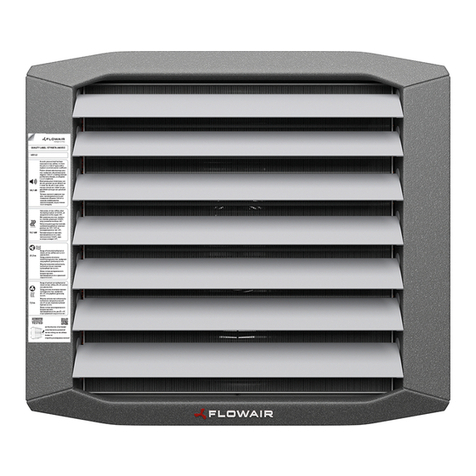
  9. flowair LEO FB 9 Guide

flowair LEO FB 9 Guide

LEO FB 9 | 15 | 25 | 45 | 65 | 95 DTR LEO FB 91525456595 12.02.
ENPLDERU
EN
WATER HEATER
TECHNICAL DOCUMENTATION
OPERATION MANUAL
PL
NAGRZEWNICA WODNA
DOKUMENTACJA TECHNICZNA
DE
WASSERLUFTERHITZER
TECHNISCHE DOKUMENTATION
BETRIEBSANLEITUNG
RU
www.flowair.com | 2
TABLE OF CONTENTS
1. General Information. ........................................................................ 3
2. Application........................................................................................ 3
3. Technical Data . ............................................................................... 4
4. Heat capacity sheet. ........................................................................ 5
5. Horizontal range . ............................................................................. 6
6. Installation ........................................................................................ 6
7. Controls............................................................................................ 9
7.1. Control equipment. ....................................................................... 9
7.2. Connection diagrams . ................................................................ 12
8. Start-Up and Operation. ................................................................. 17
9. Service ........................................................................................... 19
............................................................................... 3
2. Zastosowanie . .................................................................................... 3
3. Dane techniczne. ................................................................................ 4
4. Tabele mocy grzewczych . .................................................................. 5
5 poziomy . ................................................................................. 6
................................................................................................ 6
7. Automatyka ......................................................................................... 9
7.1. Elementy automatyki. .................................................................... 9
7
................................................................... 12
8. Uruchomienie i eksploatacja. ............................................................ 17
9. Serwis ............................................................................................... 19
INHALTSVERZEICHNIS
1. Allgemeine Informationen . ................................................................. 3
2. Einsatz ............................................................................................... 3
3. Technische Daten. ............................................................................. 4
4. Heizleistungstabellen. ........................................................................ 5
5. Luftreichweite . ................................................................................... 6
6. Montage ............................................................................................. 6
7. Steuerung........................................................................................... 9
7
................................................................................. 9
7.2. Anschlussschema. .................................................................... 12
8. Inbetriebnahme und Betrieb. ............................................................ 18
9. Instandhaltung. ................................................................................ 19
1......................................................................... 3
..................................................................................... 3
3................................................................................................................ 4
4. . .......................................................... 5
5. . ................................................................................................. 6
6........................................................................................... 6
7. ......................................................................................... 9
7
............................. 9
7................................................................ 12
8.................................................................... 18
9.......................................................................... 19
Thank you for purchasing the LEO FB water heater.
I
make revisions and changes in the operation manual at any time and
without notice, and also to make changes in the device without
influencing its operation.
This manual is an integral part
of the device and it must be delivered to
the user together with the device. In order to ensure correct operation of
the equipment, get thoroughly acquainted with this manual and keep it
for the future.
.
do wprowadzenia poprawek i zmian w
dowolnym
czasie i bez powiadomienia, a
w r a z z
Wir
Die vorliegende Bedienungseinleitung wird durch die Firma FLOWAIR
vor
vorzunehmen, die seine Funktion nicht betreffen.
korrek
t betrieben und bedient wird, machen Sie sicht mit der
Zukunft auf.
L E O
FB.
FLOWAIR
G OGOWSKI I BRZEZI SKI SP.J.
www.flowair.com | 3
1.GENERAL INFORMATION 1.
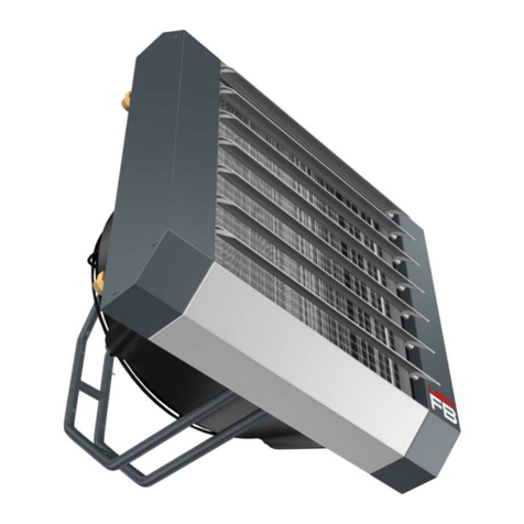
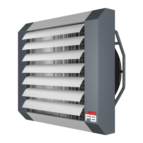
The LEO FB device group includes the following models:
LEO FB 9 device of nominal heat capacity 8.9 kW,
LEO FB 15 device of nominal heat capacity 17.4 kW,
LEO FB 25 device of nominal heat capacity 25.4 kW,
LEO FB 45 device of nominal heat capacity 46.8 kW,
LEO FB 65 device of nominal heat capacity 64.6 kW,
LEO FB 95 device of nominal heat capacity 100.1 kW.
LEO FB 9M | 15M heater with fan with an electronically commutated
(EC) motor, controlled by an external voltage signal (0 10V),
LEO FB (25/45/65/95) M heater with a built-in speed regulator,
controlled by an external voltage signal (0 10V),
LEO FB (15/25/45/65/95) S heater in standard execution.
W g
LEO FB 9
LEO FB 15
LEO FB 25
LEO FB 45 nominalnej mocy grzewczej 46,8 kW,
LEO FB 65
LEO FB 95
LEO FB 9M | 15M nagrzewnica z wentylatorem z silnikiem
elektronicznie komutowanym (EC), sterowany
10V),
LEO FB (25/45/65/95) M nagrzewnica z nabudowanym na wentylator
10V),
LEO FB (15/25/45/65/95) S nagrzewnica w wykonaniu standardowym.
1. ALLGEMEINE INFORMATIONEN 1.
Die LEO FB-Reihe besteht aus folgenden Modellen:
LEO FB 9 k W ,
LEO FB 15
LEO FB 25
LEO FB 45
LEO FB 65
LEO FB 95
LEO FB 9M | 15M tierten Motor
(EC) ausgestattet, angesteuert mit einem externen Spannungssignal (0
10V),
LEO FB (25/45/65) M ein Lufterhitzer mit am Ventilator eingebauten
Geschwindigkeitsregler, angesteuert mit einem externen
Spannungssignal (0 10V),
LEO FB (15/25/45/65) S .
LEO FB
LEO FB 9
LEO FB 15
LEO FB 25
LEO FB 45 46,8
LEO FB 65
LEO FB 95
LEO FB 9M | 15M
-EC),
LEO FB (25/45/65) M
(0
LEO FB (15/25/45/65) S .
2. APPLICATION 2. ZASTOSOWANIE
LEO FB heaters make up a decentralised heating system.
The air
streaming through the heat exchanger filled with hot water is warmed
up. Unit heaters are used for heating large volume
buildings: general,
industrial and public buildings etc. The devices are designed for indoor
use where maximum air dustiness does not exceed 0,3 g/m3 .
Units are
built using copper, aluminum and galvanized steel. It is prohibited to
install units in the areas where environment inside
can causes in
rusting.
nadmuchiwane
maksymalnym zapyleniu powietrza 0,3g/m3 .
z aluminium, miedzi oraz
stali cynkowej
2. EINSATZ 2.
Die LEO-
Lufterhitzer bilden dezentrale Heizungssysteme. Sie werden
mit Heizungswasser gespeist. Das Wasser gibt im
Die Warmwasser-
/m3 .
Die
korrodieren.
LEO FB
.
www.flowair.com | 4
3. TECHNICAL DATA 3. DANE TECHNICZNE 3. TECHNISCHE DATEN 3.
FB 95 FB 9 | 15 | 25 | 45 | 65
FB 9M | 15M FB 9S | 15S FB 25 S|M FB 45 S|M FB 65 S|M FB 95 S|M
Dimension [mm] | Wymiar [mm] |
[ ]
A500 500 600 600 600 600
B540 540 640 640 640 1175
C525 525 610 610 630 610
D335 275 350 350 370 350
E345 345 440 440 440 440
Max airflow [m3 /h ]
powietrza [m3/h ] | Max. Luftdurchfluss [m3 /h ] | .
[ 3]
2000 2000 4400 4100 3900 8500
Power supply [V/Hz] | Zasilanie [V/Hz] |
Stromversorgung [V/Hz] | [ /] 230/50 230/50 230/50 230/50 230/50 230/50
Max current consumption [A] [A] |
Max. Stromaufnahme [A] | .
[A]
0,25 0,4 1,2 1,2 1,2 2,4
Max power consumption [W] | Mak. [ W ] |
Max. Leistungsaugnahme [W] | .
[ ]
57,5 92 280 280 280 560
IP/ Insulation class | IP/Klasa izolacji |
IP/Isolierungsklasse | IP/ 54 /F 54 /F 54 /F 54 /F 54 /F 54 /F
Max acoustic pressure level [dB(A)] | Max. poziom
[dB(A)] | .
[(A)]
45* 45* 51* 51* 51* 53*
Max heating water temperature [o C]
| Max. temp. wody
grzewczej [oC] | Max. Temperatur des Heizwassers
[oC] | . . [o C]
95 95 130 130 130 130
Max operating pressure [MPa]
robocze [MPa] | Max. Betriebsdruck [MPa] | .
[M a]
1,6 1,6 1,6 1,6 1,6 1,6
Anschluss |
Max working temperature [oC] | Maks. temperatura
pracy [oC] | Maximale Betriebstemperaur [oC] |
lub
[oC]
50 50 60 60 60 60
Device mass [kg] [kg] |
[kg] | [ ] 12 12 16,9 18,1 20,4 34,5
Mass of device filled with water [kg] | Masa
[kg] | Gewicht des wasser-
[kg] | ,
[ ]
13,2 13,2 17,9 20,1 23,1 38,0
*Acoustic pressure level has been measured 5m from the unit in a 1500m3 space with a medium sound absorption coefficient| |
3, w
*Raumvolmen 1500m3
3
www.flowair.com | 5
4. HEAT CAPACITY SHEET 4. TABELE MOCY GRZEWCZYCH
4. HEIZLEISTUNGSTABELLEN 4.
Tp1 PT Qw Tp2 PT Qw Tp2 PT Qw Tp2 PT Qw Tp2 PT Qw Tp2
kW l/h kPa k W l/h kPa kW l/h kPa kW l/h kPa k W l/h kPa
LEO FB 9 V = 2000m3/h
08,9 392 2,3 14,5 7,5 331 1,8 12,0 6,2 269 1,3 10,0 4,7 205 0,8 8,0 4,4 408 2,8 7,5
58,2 363 2,0 19,0 6,9 302 1,5 16,0 5,5 240 1,0 14,0 4,0 175 0,6 12,0 3,6 357 2,2 11,5
10 7,6 333 1,7 23,0 6,2 273 1,3 20,0 4,8 211 0,8 18,0 3,3 144 0,4 15,5 3,0 305 1,7 15,0
15 6,9 304 1,5 27,0 5,6 244 1,0 25,0 4,2 182 0,6 22,0 2,5 109 0,3 19,0 2,2 252 1,2 18,5
20 6,3 276 1,2 31,0 4,9 216 0,8 29,0 3,5 153 0,5 26,0 1,7 74 0,1 23,0 1,5 198 0,8 22,5
LEO FB 15 V = 2000m3/h
017,4 769 6,9 28,5 14,9 656 5,3 24,5 12,4 542 3,9 20,5 9,8 428 2,7 16,0 9,6 836 9,0 16,0
516,1 711 6,0 32,0 13,6 599 4,5 28,0 11,1 487 3,2 23,5 8,6 373 2,1 19,5 8,4 728 7,0 19,0
10 14,8 655 5,2 35,5 12,4 544 3,8 31,0 9,9 432 2,6 27,0 7,3 318 1,6 22,5 7,1 621 5,3 22,0
15 13,6 599 4,4 38,5 11,1 489 3,1 34,5 8,6 378 2,0 30,0 6,1 263 1,1 25,5 5,9 516 3,8 25,5
20 12,3 544 3,7 41,5 9,9 435 2,5 37,5 7,4 324 1,6 33,0 4,8 207 0,7 18,5 4,7 411 2,5 28,5
LEO FB 25 V = 4400m3/h
025,4 1121 11,7 16,0 21,6 950 8,9 13,5 17,8 779 6,4 11,0 13,9 606 4,2 9,0 14,0 1216 15,1 9,0
523,5 1037 10,1 20,0 19,7 867 7,5 17,5 15,9 697 5,2 15,0 12,1 525 3,2 12,5 12,1 1056 11,6 13,0
10 21,6 953 8,7 24,0 17,9 785 6,3 21,5 14,1 617 4,2 19,0 10,2 445 2,4 16,5 10,3 897 8,6 16,5
15 19,7 871 7,4 28,0 16,0 704 5,1 25,5 12,3 537 3,2 23,0 8,4 365 1,7 20,5 8,5 740 6,1 20,5
20 17,9 790 6,2 32,0 14,2 624 4,1 29,5 10,5 457 2,4 27,0 6,5 283 1,1 24,5 6,7 585 4,0 24,5
LEO FB 45 V = 4100m3/h
046,8 2067 17,5 31,5 40,1 1762 13,4 27,0 33,3 1459 9,8 22,5 26,5 1155 6,7 18,0 25,9 2251 22,7 17,5
543,3 1911 15,2 34,5 36,6 1610 11,4 30,0 29,9 1309 8,1 25,5 23,1 1008 5,2 21,0 22,5 1959 17,7 20,5
10 39,8 1758 13,0 38,0 33,2 1459 9,5 33,0 26,6 1162 6,5 28,5 19,8 862 3,9 24,0 19,2 1672 13,2 23,5
15 36,4 1607 11,0 41,0 29,9 1312 7,8 36,0 23,2 1017 5,1 31,5 16,5 719 2,8 26,5 16,0 1389 9,5 26,5
20 33,1 1459 9,2 44,0 26,5 1166 6,3 39,0 20,0 874 3,9 34,5 13,2 575 1,9 29,5 12,8 1109 6,3 29,0
LEO FB 65 V = 3900m3/h
064,6 2660 36,8 46 56,1 2288 28,7 40 47,1 1919 21,5 33 35,6 1549 15,2 25 33,4 2902 48,1 23,5
560,2 2464 32,0 48 51,3 2097 24,5 42 42,5 1731 17,9 36 31,3 1365 12,1 28 29,2 2540 37,7 26,0
10 55,4 2272 27,6 51 46,7 1909 20,7 44 37,9 1547 14,6 38 27,2 1183 9,3 30 25,1 2183 28,7 28,5
15 50,1 2084 23,6 53 42,1 1725 17,2 46 33,4 1366 11,6 40 23,0 1004 7,0 32 21,1 1833 20,9 30,5
20 46,2 1899 19,9 55 37,6 1543 14,1 49 28,9 1187 9,1 42 18,9 825 4,9 34 17,1 1488 14,4 33,0
LEO FB 95 V = 8500m3/h
0100,1 4418 55,7 32,5 86,3 3790 43,0 28,0 72,4 3167 31,7 23,5 55,7 2427 16,1 18,0 53,3 4637 53,9 17,0
592,7 4091 48,3 36,0 79,0 3470 36,5 31,0 65,2 2854 26,2 26,5 48,9 2131 12,7 21,0 46,5 4049 42,0 20,5
10 85,4 3771 41,5 39,0 71,8 3156 30,7 34,0 58,2 2545 21,3 29,5 42,2 1838 9,7 24,0 39,9 3471 31,6 23,5
15 78,3 3456 35,3 42,0 64,8 2847 25,4 37,0 51,2 2242 16,9 32,5 35,5 1549 7,1 27,0 33,3 2900 22,7 26,5
20 71,3 3146 29,7 45,0 57,9 2543 20,6 40,0 44,4 1942 13,0 35,5 28,9 1261 4,9 30,0 26,9 2337 15,3 29,5
V
PT heat capacity | moc grzewcza | Heizleistung |
Tp1 inlet air temp. | temperatura powietrza na wlocie do aparatu | Lufteintrittstemperatur |
Tp2 outlet air temp. | temperatura powietrza na wylocie z aparatu | Lufteustrittstemperatur |
Tw1 inlet water temp. | temperatura wody na zasilaniu wymiennika | Wassertemperatur im Vorlauf |
Tw2 outlet water temp. | temperatura wody na powrocie z auf |
Qw
pw Druckabfall |
www.flowair.com | 6
5. RANGE 5 5. LUFTREICHWEITE 5.
V
LHorizontal range of isothermal stream at limit speed 0,5m/s |
Isothermische Reichweite des Luftstrahles bei Grenzgeschwidigkeit 0,5m/s | ,
0,5 /
6. INSTALLATION 6
FB 9 | 15 FB 25 | FB 45 | FB 65 FB 95
A max 3,0 2,5-8,0 2,5-10,0
B 2,5-5,0 2,5-10,0 2,5-12,0
C min. 0,3 min. 0,3 min. 0,3
D min. 0,5 min. 0,5 min. 0,5
Unit heaters can be mounted to
vertical or horizontal partitions in any
position.
During the
montage, the minimal
distances from the walls and ceiling
have to be kept.
poziomych
w dowolnej pozycji.
zalecane
6. MONTAGE 6.
Die Warmwasser-
beliebig vertikal bzw. horizontal
montiert werden.
Bei der Montage sind die empfohlene
www.flowair.com | 7
6. INSTALLATION 6
1.
2.
3.
FB 9 | 15 FB 25 | FB 45 | FB 65 FB 95
A 415 515 515
B 415 515 1055
1.
As standard, LEO water heaters
are executed with hydraulic
connection on the right side
(looking from the back of the
device).
It is possible to install the
device with the hydraulic connection
located on the left side. In this case
the supply should be
connected to
the upper stub.
2. Guides (blades)
can be mounted
vertically or horizontally.
3. U-
sections to suspend the device
under the ceiling.
Removing the
brackets and mounting them in other
places of the heater is not allowed.
1.
Nagrzewnice wodne standardowo
hydraulicznym z prawej strony
strony.
do
2. Kierownice powietrza
w oknie nagrzewnicy
3.
.
nagrzewnicy.
6
. MONTAGE
6
.
1.
Die Wasserlufterhitzer sind
(von
hinten gesehen).
der Montage links befinden. In
diesem Fall soll der Vorlauf zur
angeschlossen werden.
2.
horizontal oder vertikal im Rahmen
montiert werden.
3. Die
Unterdeckenmontage. Untersangt
ist das Abschrauben von den U-
Profilen und denen Anbringen an
anderen Stellen des Lufterhitzers.
1.
2.
3.
www.flowair.com | 8
6. INSTALLATION 6
1.1 1.2
2.
3.
FB 9|15|25|45|65 FB 95
FB bracket (optional accessory).
During the montage, the minimal
distances from the walls and ceiling
have to be kept.
INSTALLATION OPTIONS:
Fig. 1.1 - Vertically to the heater
Fig. 1.2 - Horizontally to the heater (d
o
not apply to FB 95)
Fig. 2 -
At the angle of 30 or 45
degrees or parallel to the wall.
INSTALLATION STEPS (FIG. 3)
nozzle retaining screw
screw included in console mounting
set
Expansion bolts are not included in the
set. Type of the Bolts should be
chosen appropriately to the type of the
wall.
Konsola FB
:
Rys. 1.1 - Pionowo do nagrzewnicy
Rys. 1.2 - Poziomo do nagrzewnicy (nie
dotyczy FB 95)
Rys. 2 - olub
45o.
(RYS.3)
w
6
. MONTAGE
6
.
Montagekonsole FB
Bei
der Montage sind die empfohlene
Abb. 1.1 - Horizontal
Abb. 1.2 - Vertikal
(diese Angaben
Abb. 2 - Paralel oder u
nter dem Winkel
30ooder 45o.
MONTAGE-VORGEHENSWEISE
(ABB. 3)
Schraube zur Befestigung der
Montageschraube im Lieferumfang
mit Montagekonsole
Lieferumfang. Es sollen richtigen
werden.
FB
P1.1 -
P1 . 2 -
P2 -
oo
(P C. 3)
www.flowair.com | 9
7. CONTROLS 7. AUTOMATYKA
LEO FB heaters feature two basic methods for controlling the
fan
operation:
M system
based on regulation of the heater efficiency according to the
temperature. The heater operation is regulated by controllers (VNT20 or
VNTLCD) that automatically adjust its heat capacity to changing
conditions inside the room. The
in range of 0
100% depending on the temperature difference: set on the
controller and measured.
S type control
It is on/off type control. The heater operation is
regulated by a thermostat that switches on the
device in case of
temperature drop below the pre-set value. The fan can operate within 5-
step range of capacities (using five step fan speed regulator)
System M
zmienia zakresie 0
zmierzonej.
Sterowanie typu S
przypadku spadku tempera
-
stopniowym zakresie
7. STEUERUNG 7.
mit zwei
grundlegenden Steuerungen ausgestattet:
M-System -
Regelung. Der Betrieb des Lufterhitzers wird von Signalgebern (VNT20
bzw. VNTLCD) kontrolliert, die automatisch die Heizlast den
Raumbedingun
Luftvolumenstrom im 0
Temperaturunterschiedes zwischen dem Ist- und Sollwert.
Typ S-Regeulng EIN-
AUS Regelung. Der Betrieb des Lufterhitzers wird
von einem Thermostat geste
Temperaturabsenkung unter den eingestellten Sollwert einschaltet. Der
Luftvolumenstrom kann 5-
stufig eingestellt werden (mit einem
Traforegler).
LEO FB
(VNT20 VNTLCD
-
SON/OFF
7.1. CONTROL EQUIPMENT 7.1. ELEMENTY AUTOMATYKI
7.1. ZUBEH R7.1.
RA / RS Room thermostat / Room
thermostat with cool / heat
switch
Temperature adjustment
0C
Operation temperature
range: oC
Protection degree: IP30
Load carrying capacity of
the contact: inductive 3A
resistivity 10A
Termostat
pomieszczeniowy /
termostat pomieszczeniowy
Zakres nastawy 0C
Zakres temperatury pracy:
oC
IP30
indukcyjne 3A,
rezystancyjne 10A
Raumthermostat /
Raumthermostat mit
Sommer/Winter Funktion
Einstellungsbereich der 0C
Bereich der
Betriebstemperatur:
+40oC
Schutzklasse: IP30
Belastbarkeit des
Kontaktes:
induktiv 3A, resistantiv 10A
/
0C
oC
IP30
RD Room thermostat with
weekly programmer
Temperature adjustment
oC in step s
of 0.5oC
Operation temperature
range: oC
Protection degree: IP30
Power supply:
batteries 2x1,5V AA
Load carrying capacity of
the contact: inductive 2A
resistivity 5A
Termostat
pomieszczeniowy z
programatorem
tygodniowym
Zakres nastawy
temperatury:
oC co 0,5oC
Zakres temperatury pracy:
oC
IP30
baterie 2x1,5V AA
indukcyjne 2A,
rezystancyjne 5A
Raumthermostat mit
Programmeinstellung
Einstellungsbereich der
Temperatur:
o
Bereich der
Betriebstemperatur:
Schutzklasse: IP30
Versorgungsquelle:
Batterien 2x1,5V AA
Belastbarkeit des
Kontaktes:
induktiv 2A, resistantiv 5A
+5 ... + 28oC
oC
IP30
www.flowair.com | 10
7.1. CONTROL EQUIPMENT 7.1. ELEMENTY AUTOMATYKI
7.1. ZUBEH R7.1.
TR s 3-step fan speed regulator
Supply voltage: 230V
50/60Hz
Protection degree: IP54
Operation temp. range:
oC
Mass: 0,6kg
Adjustment:
FB 9 | 15 - max 1
FB 25 | 45 | 65 - not allowed
FB 95 - not allowed
Regulation steps:
1 2 3
Ur [V] / Ir [A]
TRs 110/
0.5
170/
0.5
230/
0.5
3-stopniowy regulator
230V 50/60Hz
IP54
Zakres temperatury pracy:
oC
Masa: 0,6kg
Regulacja:
FB 9 | 15 max 1
FB 25 | 45 | 65
niedozwolone
FB 95 niedozwolone
Stopnie regulacji:
1 2 3
Ur [V] / Ir [A]
TRs 110/
0,5
170/
0,5
230/
0,5
3-stufiger
Drehzahltraforegler
Versorgungsspannung:
230V 50/60Hz
Schutzklasse: IP54
Bereich der
Betriebstemperatur:
oC
Gewicht: 0,6kg
Steuerung:
FB 9 | 15 max. 1
FB 25 | 45 | 65 nicht
empfohlen
FB 95 nicht empfohlen
Regelstufen:
1 2 3
Ur [V] / Ir [A]
TRs 110/
0,5
170/
0,5
230/
0,5
3-
IP54
oC
0,6
:
FB 9 | 15
FB 25|45|65
FB 95
1 2 3
Ur Ir [A]
TRs 110/
0,5
170/
0,5
230/
0,5
TR | TRd 5-step fan speed regulator
Supply voltage: 230V
50/60Hz
Protection degree: IP54
Operation temp. range:
oC
Mass: TR 1.5kg;
TRd 2.5kg
Adjustment:
TR
FB 9 | 15 - max 2
FB 25 | 45 | 65 max 1
FB 95 - not allowed
TRd:
FB 9 | 15 - max 5
FB 25 | 45 | 65 max 2
FB 95 max 1
Regulation steps:
1 2 3 4 5
Ur [V] / Ir [A]
TR
115/
1.5
135/
1.5
155/
1.5
180/
1.5
230/
1.5
TRd
115
/2,4
135
/2,6
155/
2.8
180/
3,0
230/
3.0
5-stopniowy regulator
230V 50/60Hz
IP54
Zakres temperatury pracy:
oC
Masa: TR - 1,5kg; TRd -
2,5kg
Regulacja:
TR:
FB 9 | 15 max 2
FB 25 | 45 | 65 max 1
FB 95 - niedozwolone
TRd:
FB 9 | 15 max 5
FB 25 | 45 | 65 max 2
FB 95 max 1
Stopnie regulacji:
1 2 3 4 5
Ur [V] / Ir [A]
TR
115/
1,5
135/
1,5
155/
1,5
180/
1,5
230/
1,5
TRd
115
/2,4
135
/2,6
155/
2.8
180/
3,0
230/
3.0
5-stufiger
Drehzahltraforegler
Versorgungsspannung:
230V 50/60Hz
Schutzklasse: IP54
Bereich der
Betriebstemperatur:
oC
Gewicht: TR - 1,5kg;
TRd - 2,5kg
Steuerung:
TR:
FB 9 | 15 max. 2
FB 25 | 45 | 65 max 1
FB 95 nicht empfohlen
TRd:
FB 9 | 15 max. 5
FB 25 | 45 | 65 max 2
FB 95 max 1
Regelstufen:
1 2 3 4 5
Ur [V] / Ir [A]
TR
115/
1,5
135/
1,5
155/
1,5
180/
1,5
230/
1,5
TRd
115
/2,4
135
/2,6
155/
2.8
180/
3,0
230/
3.0
IP54
oC
TR - TRd -
:
TR:
FB 9 | 15 . 2
FB 25|45|65 . 1
FB 95
TRd:
FB 9 | 15 . 5
FB 25|45|65 . 2
FB 95 . 1
1 2 3 4 5
Ur Ir [A]
TR
115/
1,5
135/
1,5
155/
1,5
180/
1,5
230/
1,5
TRd
115
/2,4
135
/2,6
155/
2.8
180/
3,0
230/
3.0
VNT20 Fan speed controller with a
built-in room thermostat
Supply voltage: 230V 50Hz
Output control signal:
analogue 0 - 10V
Temperature adjustment
range: oC
Method of speed regulation:
potentiometer
Speed regulation range:
0 100%
Operation temperature
range:
-oC
Temperature sensor:
internal (ext. PT-1000)
Protection degree: IP20
Load carrying capacity of
the contact: inductive 3A
resistivity 8A
z wbudowanym
termostatem
50Hz
analogowy 0 - 10V
Zakres nastawy
temperatury:
oC
potencjometr
0 100%
Zakres temperatury pracy:
-oC
Czujnik temperatury:
-1000)
IP20
zaworu: indukcyjne 3A,
rezystancyjne 8A
Integrierter Steuerpanel
Versorgungsspannung:
230V 50Hz
Ausgangs-
Steuerungssignal:
analog 0 - 10V
Einstellungsbereich der
oC
Steuerungsart:
Potentiometer
Bereich des
Drehzahlreglers:
0 100%
Bereich der
Betriebstemperatur:
-oC
Temperatursensor: innen
-1000)
Schutzklasse: IP20
Belastbarkeit des
Ventilkontaktes:
induktiv 3A, resistantiv 8A
0C
100%
-oC
PT-1000)
IP20
www.flowair.com | 11
7.1. CONTROL EQUIPMENT 7.1. ELEMENTY AUTOMATYKI
7.1. ZUBEH R7.1.
VNTLCD Programmable fan speed
controller with a built-in
room thermostat
Supply voltage:
230V 50Hz
Output control signal:
analogue 0 - 10V
Temperature adjustment
range: oC
Method of speed regulation:
Manual control, LCD display
Speed regulation range:
0 100%
Operation temp. range:
-oC
Temperature sensor:
internal (optionally ext. PT-
1000)
Protection degree: IP20
Load carrying capacity of
the contact: inductive 3A
resistivity 8A
Programowalny nastawnik
termostatem
50Hz
analogowy 0 - 10V
Zakres nastawy
temperatury:
oC
Zakres regulac
0 100%
Zakres temperatury pracy:
-oC
Czujnik temperatury:
zew. PT-1000)
IP20
zaworu: indukcyjne 3A,
rezystancyjne 8A
Integrierter programmierbar
Steuerungsmodul
Versorgungsspannung:
230V 50Hz
Ausgangs-
Steuerungssignal: analog 0
- 10V
Einstellungsbereich der
oC
Steuerungsart:
Tastatur, LCD-Bildschirm
Bereich des
Drehzahlreglers:
0 100%
Bereich der
Betriebstemperatur:
-oC
Temperatursensor:
-
1000)
Schutzklasse: IP20
Belastbarkeit des
Ventilkontaktes:
induktiv 3A, resistantiv 8A
0C
100%
-oC
PT-
1000)
IP20
PT-1000 IP20 Wall-mounted temperature
sensor
Protection degree: IP20
Operation temperature
range:
-oC
Czujnik
temperatury
Zakres temperatury pracy:
-oC
Temperaturmessung
Schutzklasse: IP20
Bereich der
Betriebstemperatur:
-oC
IP20
-oC
PT-1000 IP65 Wall-mounted temperature
sensor
Protection degree: IP65
Operation temperature
range:
-oC
temperatury
Zakres temperatury pracy:
-oC
Temperaturmessung
Schutzklasse: IP65
Bereich der
Betriebstemperatur:
-oC
IP65
-oC
R10 Signal distributor
Protection degree: IP54
Operation temperature
range: oC
Zakres temperatury pracy:
oC
Signalverteiler
Schutzklasse: IP54
Betriebstemperatur:
oC
IP54
40oC
www.flowair.com | 12
7.1. CONTROL EQUIPMENT 7.1. ELEMENTY AUTOMATYKI
7.1. ZUBEH R7.1.
SRS
| SRV2d Two-way valve with
actuator
Protection degree: IP44
Supply voltage: 200 240V
50/60Hz
Max. medium temperature:
+130oC
Max. operating pressure:
1,6MPa
Kvs: SRS 3.5; SRV2d 5
Connection: SRS
SRV2d
Runtime: 2,5min.
Mounting: on the return line
of the heat medium from the
heater.
z
240V 50/60Hz
Maks. temperatura
czynnika: +130oC
1,6MPa
Kvs: SRS 3.5; SRV2d 5
SRV2d
Czas otwarcia: 2,5min.
czynnika grzewczego z
nagrzewnicy
2-Wege-Regelventil mit
Stellmotor
Schutzklasse: IP44
Versorgungsspannung:
200 240V 50/60Hz
Max. Temperatur des
Mediums: +130oC
Max. Betriebsdruck:
1,6MPa
Kvs: SRS 3.5; SRV2d 5
Anschluss: SRS
SRV2d
Laufzeit: 2,5min.
czynnika grzewczego z
nagrzewnicy
IP44
200
oC
1,6M a
Kvs
Kvs: SRS
3.5; SRV2d 5
: SRS
SRV2d
SRS3d | SRV3d
Three-way valve with
actuator
Protection degree: IP40
Supply voltage: 200 240V
50/60Hz
Max. medium temperature:
+95oC
Max. operating pressure:
2MPa
Kvs: SRS3d 3,4; SRV3d 7
Connection: SRS3d
SRV3d
Runtime: 7s
Mounting: on the supply line
of the heating medium to
the heater.
z
240V 50/60Hz
Maks. temperatura
czynnika: +95oC
M
2MPa
Kvs: SRS3d 3,4; SRV3d 7
SRS3d
SRV3d
Czas przebiegu: 7s
nagrzewnicy czynnikiem
grzewczym
3-Wege-Regelventil mit
Stellmotor
Schutzklasse: IP40
Versorgungsspannung:
200 240V 50/60Hz
Max. Temperatur des
Mediums: +95oC
Max. Betriebsdruck: 2MPa
Kvs: SRS3d 3,4; SRV3d 7
Anschluss: SRS3d
SRV3d
Laufzeit: 7s
Mediums
IP40
200
oC
2M a
Kvs
SRS3d 3,4;
SRV3d 7
: SRS3d
SRV3d
7.2. CONNECTION DIAGRAMS 7.2. SCHEMATY POD CZE
7.2. ANSCHLUSSSCHEMA 7.2.
Wires size should be chosen by the designer.
Das Durchmesser von den Leitungen sollen vom Planer angegeben
werden.
www.flowair.com | 13
7.2. CONNECTION DIAGRAMS 7.2. SCHEMATY POD CZE
7.2. ANSCHLUSSSCHEMA 7.2.
S
Wires size should be chosen by the designer
A Supply of the heating medium to the heater
AB Supply of the heating medium
B The exit of the heat medium to the return line of the heater
a blue; b black; c brown
Das Durchmesser von den Leitungen sollen vom Planer angegeben werden.
A Vorlauf des Heizmediums zum Lufterhitzer
AB Vorlauf des Heizmediums
B
a blau; b Schwarz; c braun
A doprowadzenie czynnika grzewczego do nagrzewnicy
AB doprowadzenie czynnika grzewczego
B
a niebieski; b czarny; c
-
-
-
b -
www.flowair.com | 14
7.2. CONNECTION DIAGRAMS 7.2. SCHEMATY POD CZE
7.2. ANSCHLUSSSCHEMA 7.2.
M
Wires size should be chosen by the designer
A Supply of the heating medium to the heater
AB Supply of the heating medium
B The exit of the heat medium to the return line of the heater
a blue; b black; c brown
Das Durchmesser von den Leitungen sollen vom Planer angegeben werden.
A Vorlauf des Heizmediums zum Lufterhitzer
AB Vorlauf des Heizmediums
B
a blau; b Schwarz; c braun
A doprowadzenie czynnika grzewczego do nagrzewnicy
AB doprowadzenie czynnika grzewczego
B
a niebieski; b czarny; c
-
-
-
b -
www.flowair.com | 15
7.2. CONNECTION DIAGRAMS 7.2. SCHEMATY POD CZE
7.2. ANSCHLUSSSCHEMA 7.2.
M
Wires size should be chosen by the designer
A Supply of the heating medium to the heater
AB Supply of the heating medium
B The exit of the heat medium to the return line of the heater
a blue; b black; c brown
Das Durchmesser von den Leitungen sollen vom Planer angegeben werden.
A Vorlauf des Heizmediums zum Lufterhitzer
AB Vorlauf des Heizmediums
B
a blau; b Schwarz; c braun
A doprowadzenie czynnika grzewczego do nagrzewnicy
AB doprowadzenie czynnika grzewczego
B
a niebieski; b czarny; c
-
-
-
b -
www.flowair.com | 16
7.2. CONNECTION DIAGRAMS 7.2. SCHEMATY POD CZE
7.2. ANSCHLUSSSCHEMA 7.2.
M
1 or 4 PT-1000 sensors may be connected simultaneously to the controllers VNT20 and VNTLCD.
Do -1000.
oder 4 Sensoren PT-1000 angeschlossen werden.
VNT VNTLCD PT-1000.
www.flowair.com | 17
8. START-UP AND OPERATION 8. URUCHOMIENIE I EKSPLOATACJA
Guidelines for System Connection
The connection should be executed in a way which does not
induce stresses.
It is
recommended to install vent valves at the highest point
of the system.
The system should be executed so that, in the case of a
failure, it is possible to disassemble the device. For this
purpose it is best to use shut-off valves just by the device.
The sys
tem with the heating medium must be protected
against an increase of the heating medium pressure above
the permissible value (1.6 MPa).
While screwing exchanger to pipeline -
connecting stubs has
to be hold by wrench.
Start Up
Before connecting the power
supply check the correctness of
connection of the fan motor and the controllers. These
connections should be executed in accordance with their
technical documentation.
Before connecting the power supply check whether the mains
voltage is in accordance wit
h the voltage on the device data
plate.
Before starting the device check the correctness of connection
of the heating medium conduits and the tightness of the
system.
The electrical system supplying the fan motor should be
additionally protected with a cir
cuit breaker against the effects
of a possible short-circuit in the system.
Starting the device without connecting the ground conductor is
forbidden.
Operation
The device is designed for operation inside buildings, at
temperatures above 0oC. In low
there is a danger of freezing of the medium.
The manufacturer bears no responsibility for damage of the
heat exchanger resulting from freezing of the medium in the
exchanger. If operation of the device is expected at
temperatures l
used as the heating medium, or special automatic systems
should be used for protecting against freezing of the medium
in the exchanger.
It is forbidden to place any objects on the heater or to hang any
objects on the connecting stubs.
The device must be inspected periodically.
In the case of
incorrect operation of the device it should be switched off
immediately.
It is forbidden to use a d
amaged device. The manufacturer
bears no responsibility for damage resulting from the use of a
damaged device.
If it is necessary to clean the exchanger, be careful not to
damage the aluminium lamellas.
For the time of performing inspection or cleaning the
device,
the electrical power supply should be disconnected.
In case water is drained from the device for a longer period of
time, the exchanger tubes should be emptied
with compressed
air.
It is not allowed to make any modification in the unit. Any
modification causes in warranty loss.
punkcie instalacji.
(1,6 MPa).
Uruchomienie
jest zgodne z
instalacji
dodatkowo zabezpieczona bezpiecznikiem przed skutkami
ewentualnego zwarcia w instalacji.
niedozwolone.
Eksploatacja
w oC.W
a czynnika.
www.flowair.com | 18
8. INBETRIEBNAHME UND BETRIEB 8.
Anschlusshinweise
Der Anschluss soll spannungsfrei erfolgen.
Installation zu lokalisieren.
dass im Falle einer Panne der Apparat
leicht demontiert werden
zu montieren.
Eine Anlage mit dem Heizmedium muss vor dem Druckanstieg
werden.
Inbetriebnahme
Bevor die Versorgung eingeschaltet wird, soll der korrekte
Bevor die Versorgung eingeschaltet wird, soll gepr
die Netzspannung mit der Spannungsangabe am Datenschild
Bevor die Anlage eingeschaltet wird, soll der korrekte Anschluss
werden.
Die elektrische Installation der V
ersorgung des Ventilatormotors
muss mit einer Sicherung versehen werden, die vor Folgen eines
Es ist verboten, die Anlage ohne angeschlossenen Erdungskabel in
Betrieb zu nehmen.
Betrieb
o
Medium einfrieren.
verursacht
werden. Soll die Anlage in Temperaturen betrieben
anzuwenden, oder sind spezielle automatische Vorrichtungen zu
verwenden, die dem Einfrieren des Heizwassers im
Hersteller
muss unbedingt die elektrische Versorgung abgeschaltet werden.
Druckluft durchzublasen.
Garantiverlust.
M a).
oCC
-
www.flowair.com | 20

Other manuals for LEO FB 9

2

This manual suits for next models

16

Other flowair Water Heater manuals

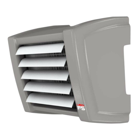
flowair LEO AGRO CR User manual

flowair

flowair LEO AGRO CR User manual

flowair LEO FS Series User manual

flowair

flowair LEO FS Series User manual

flowair LEO FB User manual

flowair

flowair LEO FB User manual

flowair LEO FB 9 User manual

flowair

flowair LEO FB 9 User manual

flowair LEO FL 30 Guide

flowair

flowair LEO FL 30 Guide

flowair LEO AGRO User manual

flowair

flowair LEO AGRO User manual

flowair LEO AGRO User manual

flowair

flowair LEO AGRO User manual

flowair LEO KMFS S User manual

flowair

flowair LEO KMFS S User manual

flowair LEO AGRO HT Guide

flowair

flowair LEO AGRO HT Guide

flowair LEO FB 15 User manual

flowair

flowair LEO FB 15 User manual

flowair LEO INOX 25 User manual

flowair

flowair LEO INOX 25 User manual

flowair LEO FB 95 User manual

flowair

flowair LEO FB 95 User manual

flowair LEO FS S Guide

flowair

flowair LEO FS S Guide

flowair LEO AGRO CR Guide

flowair

flowair LEO AGRO CR Guide

flowair LEO FS User manual

flowair

flowair LEO FS User manual

flowair AGRO SP User manual

flowair

flowair AGRO SP User manual

flowair LEO INOX 25 Guide

flowair

flowair LEO INOX 25 Guide

flowair LEO AGRO CR Guide

flowair

flowair LEO AGRO CR Guide

flowair LEO FS S Guide

flowair

flowair LEO FS S Guide

flowair AGRO SP User manual

flowair

flowair AGRO SP User manual

flowair LEO FB 15/25/45/65 User manual

flowair

flowair LEO FB 15/25/45/65 User manual

flowair AGRO HT Series User manual

flowair

flowair AGRO HT Series User manual

Popular Water Heater manuals by other brands

Rinnai REU-58E installation instructions

Rinnai

Rinnai REU-58E installation instructions

A.O. Smith 315456-002 Installation instructions and use and care guide

A.O. Smith

A.O. Smith 315456-002 Installation instructions and use and care guide

Baxi 300i manual

Baxi

Baxi 300i manual

clage MBH 3 7 Series Operating and installation instructions

clage

clage MBH 3 7 Series Operating and installation instructions

DAYLIFF ULTRASUN UFS Installation & operating manual

DAYLIFF

DAYLIFF ULTRASUN UFS Installation & operating manual

Lochinvar Armor AW 150 thru 500 Replacement parts list

Lochinvar

Lochinvar Armor AW 150 thru 500 Replacement parts list

clage Zip InLine Series Installation instructions & user manual

clage

clage Zip InLine Series Installation instructions & user manual

Ariston ABS VLS EVO INOX PW 100 Assembly and operation instructions

Ariston

Ariston ABS VLS EVO INOX PW 100 Assembly and operation instructions

Pentair Myers MS Series Installation and operation manual

Pentair

Pentair Myers MS Series Installation and operation manual

OSO HOTWATER Wally-W 30 manual

OSO HOTWATER

OSO HOTWATER Wally-W 30 manual

STIEBEL ELTRON DCE 3-1 Trend Operation and installation

STIEBEL ELTRON

STIEBEL ELTRON DCE 3-1 Trend Operation and installation

Midea M2005 Installation and operation guide

Midea

Midea M2005 Installation and operation guide

Ferroli SKY ECO F Instructions for use, installation and maintenance

Ferroli

Ferroli SKY ECO F Instructions for use, installation and maintenance

Intellihot iN199A Installation & operation manual

Intellihot

Intellihot iN199A Installation & operation manual

Bradford White MITW40L Series Replacement parts list

Bradford White

Bradford White MITW40L Series Replacement parts list

CORBERO CTWG15CD user manual

CORBERO

CORBERO CTWG15CD user manual

Bosch GWH 1000 user guide

Bosch

Bosch GWH 1000 user guide

Reflex Fillcontrol Plus Compact operating manual

Reflex

Reflex Fillcontrol Plus Compact operating manual

manuals.online logo
manuals.online logoBrands
  • About & Mission
  • Contact us
  • Privacy Policy
  • Terms and Conditions

Copyright 2025 Manuals.Online. All Rights Reserved.