8
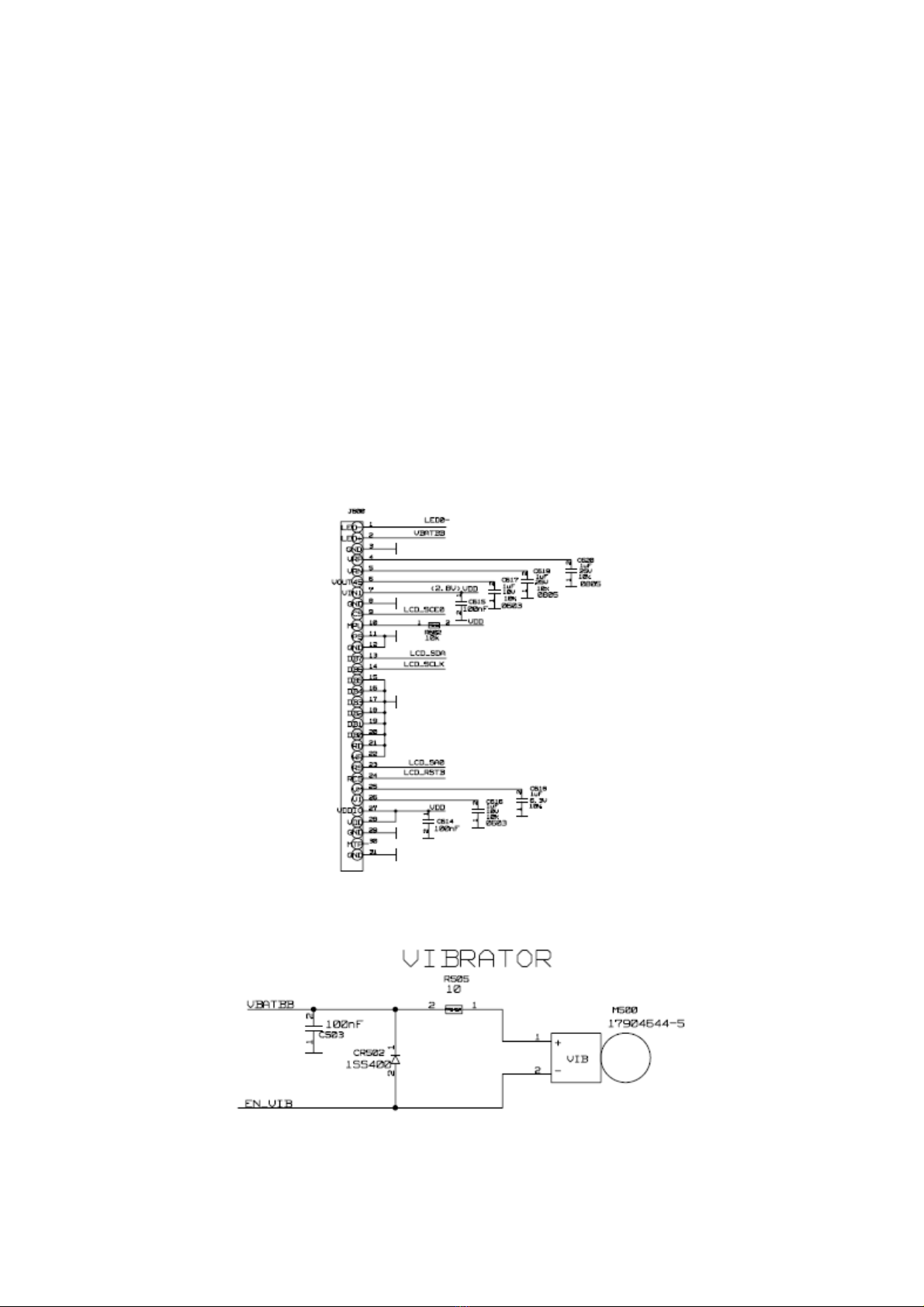
board is good. Then we need check whether the diode(CR502) polarity is correct
and the diode is damaged or not. At last, we adjust the digital power to 2 V,
plus the two control points on the vibrator. If the vibrator do not vibrates,
it illustrates that the vibrator is broken, and replace a new one. If the vibrator
vibrates, it indicates that the control signal has not come to the vibrator.
If the control signal has not been output, we need re-weld or replace the main
chip.
2.6 Un-downloading software
The failure of main board’s proper downloading is mostly due to cold solder
joint or welding. Firstly, the serial port connections between the PC and mobile
phone should be checked. And the fault usually occurs in the pin of the power
management module and connectors I \ O, as well as resistors R516, R517. First
we need look over the welding of these devices with a magnifying glass, then
plug the download cable to see whether the current is normal, if the current
is large (for example, 300mA and above), then there is VCHG or VBAT to ground
short-circuit phenomenon. This time the power should be cut off as soon as
possible, and then find out the short-circuit point. If the current is greater
than the normal value (about 300mA) but not particularly large, there may be
short circuit from the regulator output to ground. And at this time VCORE (1.8V),
VIO (2.8V), VA (2.8V), VTCXO (2.8V), VRTC (1.5V), VMEM (2.8V) and other voltage
should be checked to see if they are normal. If there is an exception, the bad
welding place can be identified. If the current is very small or even no, checking
should be focused on whether the power management module and connectors I \
O is poor welding. In addition, the plug of download wire may cause poor
connections because of long time use. At this time plug the plug again to see
if the problem disappears. While downloading, the 26MHz clock signal is required
apart from the above a number of power supply and the oscilloscope can be used
to test if 26MHz signals are normal. MA301 pin22 should be first checked whether
it has the 26MHz output. If you do not check the MA301 and around the capacitor,
check the voltage input.
The following diagram (Figure 11):
(Note: the measured waveforms are different as
the digital oscilloscope scanning
frequency is different. But the frequency value is of a certain degree.)
Downloading software is mainly the communication between CPU and FLASH,
including the control bus, addresses bus and data bus. If no problems have been
investigated out of the external circuit, and the CPU and FLASH welding are
all well, then the problem may finally lies in the PCB itself, so remove CPU
and FLASH, to check whether the trace is broken or not.