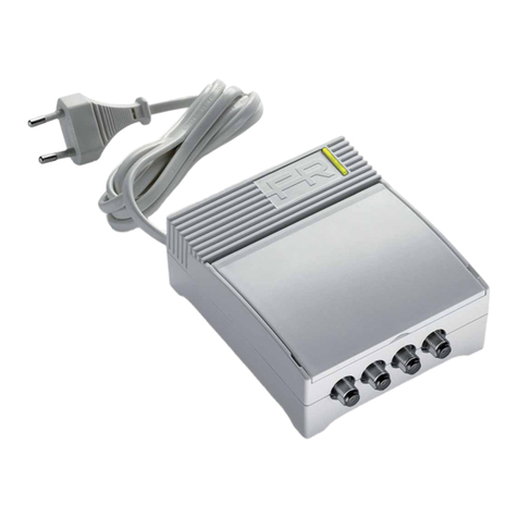
Fracarro MBJ EVO LTE Series User manual

MBJ EVO LTE Series
ITA: Centralino multingressi TV con Tecnologia A.B.L.A. (Automatic Building Level Adjustment)
ENG: TV Multiband ampli er with A.B.L.A Technology (Automatic Building Level Adjustment)
FRA: Ampli cateur Multibandes avec Technologie A.B.L.A (Automatic Building Level Adjustment)
ITA: ISTRUZIONI PER L’USO
ENG: OPERATING INSTRUCTIONS
FRA: NOTICE D’UTILISATION
ITA: 1. AVVERTENZE PER LA SICUREZZA
L’installazione del prodotto deve essere eseguita da personale quali cato in conformità alle leggi e normative locali sulla sicurezza.
Fracarro Radioindustrie di conseguenza è esonerata da qualsivoglia responsabilità civile o penale conseguente a violazioni delle norme giuridiche
vigenti in materia e derivanti dall’improprio uso del prodotto da parte dell’installatore, dell’utilizzatore o di terzi.
L‘installazione del prodotto deve essere eseguita secondo le indicazioni di installazione fornite, al ne di preservare l‘operatore da eventuali
incidenti e il prodotto da eventuali danneggiamenti. Non togliere il coperchio dell’alimentatore, parti a tensione pericolosa possono risultare
accessibili all‘apertura dell‘involucro.
AVVERTENZE PER L’INSTALLAZIONE
• Umidità e gocce di condensa potrebbero danneggiare il prodotto. In caso di condensa, prima di utilizzare il prodotto, attendere che sia
completamente asciutto.
• Maneggiare con cura. Urti impropri potrebbero danneggiare il prodotto.
• Lasciare spazio attorno al prodotto per garantire una ventilazione suf ciente.
• L’eccessiva temperatura di lavoro e/o un eccessivo riscaldamento possono compromettere il funzionamento e la durata del prodotto.
• Non installare il prodotto sopra o vicino a fonti di calore o in luoghi polverosi o dove potrebbe venire a contatto con sostanze corrosive.
• In caso di montaggio a muro utilizzare tasselli ad espansione adeguati alle caratteristiche del supporto di ssaggio.
La parete ed il sistema di ssaggio devono essere in grado di sostenere almeno 4 volte il peso dell’apparecchiatura.
• ATTENZIONE: Per evitare di ferirsi, questo apparecchio deve essere assicurato alla parete secondo le istruzioni di installazione.
• L‘apparecchio deve essere installato in modo che la spina di alimentazione di rete sia facilmente accessibile.
• Il prodotto non deve essere esposto a gocciolamento o a spruzzi d’acqua e va pertanto installato in un ambiente asciutto, all’interno di edi ci.
• Il prodotto deve essere collegato all’elettrodo di terra dell’impianto d’antenna conformemente alla norma EN 60728-11.
La vite \ faston predisposta per tale scopo è contrassegnata con il simbolo .
• Si raccomanda di attenersi alle disposizioni della norma EN 60728-11 e di non collegare tale vite alla terra di protezione della rete elettrica di
alimentazione.
Simbolo di classe II Simbolo di terra dell’impianto d’antenna

2
AVVERTENZE GENERALI
In caso di guasto non tentate di riparare il prodotto altrimenti la garanzia non sarà più valida.
Le informazioni riportate in questo manuale sono state compilate con cura, tuttavia Fracarro Radioindustrie S.r.l. si riserva il diritto di apportare in
ogni momento e senza preavviso, miglioramenti e/o modiche ai prodotti descritti nel presente manuale.
Consultare il sito www.fracarro.com per le condizioni di assistenza e garanzia.
ENG: 1. SAFETY WARNINGS
The product can only be installed by qualied personnel in compliance with local safety laws and regulations. Fracarro Radioindustrie is exempt
from all civil and criminal responsibility due to breaches of current legislation derived from the improper use of the product by the installer, user
or third parties. The product must be used in full compliance with the instructions given in this manual in order to protect the operator from all
possible injury and the product from being damaged. Never remove the product cover as there are live parts underneath it.
INSTALLATION PRECAUTIONS
• Damp and droplets from condensation could damage the product. Consequently, always wait for the product to be perfectly dry before use.
• Handle with care. Any improper impact could damage the product.
• Leave plenty of space around the product to ensure sufcient ventilation.
• High temperatures or overheating could compromise the operation and duration of the product.
• Do not install the product above or close to sources of heat, in dusty atmospheres or where it could be exposed to corrosive substances.
• If the product is installed on the wall, use proper expansion bolts suitable to the xing support.
The wall and the xing support must be able to bear at least 4 times the equipment weight.
• Attention: to avoid being hurt, the unit must be mounted to the wall/oor according to the installation instructions.
• The unit must be installed in order for the wall outlet to be easily reached.
• The product must not be exposed to water droplets and it must be installed in a dry environment indoors.
• The unit must be connected to the ground electrode of the antenna system, in compliance with the EN 60728-11 standard.
The earth screw/Faston connector is indicated with the symbol .
• It is important to observe the provisions of the EN60728-11 standard and not to connect this screw (terminal) (product) to the power supply
earth line.
Class II symbol Earth screw/Faston connector symbol
GENERAL WARNING
In the event of a malfunction, do not try to x the product as the guarantee would be invalidated.
Although the information given in this manual has been prepared carefully and thoughtfully,
Fracarro Radioindustrie S.r.l. reserves the right to modify it without notice and to improve and/or modify the product described in this manual.
See the website www.fracarro.com to have information relevant to the technical support and product guarantee.
FRA: 1. CONSIGNES DE SECURITE
• L’humidité et les gouttes de condensation, pourraient endommager l’appareil.
En cas de condensation, attendre que le produit soit complètement sec avant de l’utiliser. Manier avec soin.
• Les chocs pourraient endommager le produit.
• Laisser de l’espace autour du produit pour garantir une ventilation sufsante.
• La température excessive de fonctionnement et/ou un réchauffement excessif peuvent nuire au fonctionnement et à la durée du produit.
• Ne pas installer le produit sur ou près des sources de chaleur, dans des endroits très poussiéreux ou en contact avec des substances
corrosives.
• En cas de montage mural, utiliser des chevilles à expansion correspondant aux caractéristiques du support de xation.
La paroi et le système de xation doivent être en mesure de supporter au moins 4 fois le poids de l’appareil.
• ATTENTION : Pour ne pas se blesser, xer le produit au mur/sol en suivant les instructions de montage.
Installer le produit de façon que la che d’alimentation de secteur soit facilement accessible.
• Le produit ne doit pas être exposé à l’égouttement ou aux éclaboussures d’eau et il doit donc être installé dans un endroit sec, à l’intérieur.
• Le produit doit être connecté à l’électrode de terre de l’installation de l’antenne en conformité avec la norme EN 60728-11.
La vis prévue à cet effet est caractérisée par le symbole .
• Il est conseillé de respecter les dispositions de la norme EN60728-11 et de ne pas relier cette vis (borne) (produit) à la terre de protection du
secteur.
Classe II Symbole électrode de terre de l’installation de l’antenne
AVERTISSEMENTS GÉNÉRAUX
En cas de panne, ne pas tenter de réparer le produit, sans quoi la garantie ne sera plus valable. Les informations indiquées dans ce mode
d’emploi ont été renseignées soigneusement ; toutefois, Fracarro Radioindustrie S.r.l. se réserve le droit d’améliorer et/ou de modier à
tout moment et sans préavis les produits décrits dans ce mode d’emploi. Consulter le site www.fracarro.com pour connaître les conditions
d’assistance et de garantie.
3
ITA: 2. DESCRIZIONE DEL PRODOTTO
La Nuova serie MBJ evo LTE con tecnologia A.B.L.A. (Automatic Building Level Adjustment), è una gamma completa di ampli catori multibanda
con regolazione e controllo automatico del livello di uscita (funzione A.B.L.A), e ltro LTE integrato per ogni Banda UHF e Banda V. Assemblati in
contenitori schermati con tecnologia SMD con bassa gura di rumore, adatti a risolvere le attuali esigenze di installazione. La gamma completa
dispone di modelli con diversi ingressi, guadagni e livelli di uscita, che consentono all’installatore la possibilità di scegliere al meglio il modello più
adatto in funzione alla dimensione della rete di distribuzione TV che si vuole andare a servire.
In tutti i modelli è presente una protezione in caso di corto circuito (autoripristinante alla rimozione del corto circuito) con segnalazione tramite
l’immediato spegnimento del led di alimentazione, inoltre è possibile abilitare tramite dip-switch la tele-alimentazione sugli ingressi per alimen-
tare un eventuale pre-ampli catore da palo. I contenitori sono realizzati in ABS auto estinguente (classe V0) di ridotte dimensioni e offrono la
possibilità di ssaggio a muro o su barra DIN.
ENG: 2. PRODUCT DESCRIPTION
The new MBJ evo LTE series equipped with A.B.L.A. (Automatic Building Level Adjustment) technology is a complete range of multiband
ampli ers with automatic adjustment and control of the output level (function A.B.L.A), and an LTE integrated lter for each UHF band and
V band. Assembled in shielded boxes with SMD technology and low noise gure, they are suitable to solve the current needs of installation.
The range includes models with different inputs, gains and output levels that allows the installer to select the most suitable model for the
TV distribution network that he is working on. All models are equipped with short-circuit protection (self-restoring when the short-circuit
is removed) signalled by the power Led that goes off immediately when the short circuit is removed. Furthermore, the dip-switch enables
a remote power supply to the inputs to feed a mast pre-ampli er, if any. The boxes are made of self-extinguish ABS material (class V0) of
compact dimensions and can be mounted either on the wall or on the DIN bar.
FRA: 2. DESCRIPTION DU PRODUIT
La nouvelle série MBJ evo LTE avec technologie A.B.L.A. (Automatic Building Level Adjustment), est une gamme complète d‘ampli cateurs
multibande avec réglage et contrôle automatique du niveau de sortie (fonction A.B.L.A.), et ltrt LTE intégré pour la bande UHF et la bande V.
Réalisés avec technologie SMD, ils sont assemblés dans des boîtiers blindés et disposent d‘un très faible facteur de bruit.
La gamme complète est composée de modèles avec plusieurs entrées, différents gains et niveaux de sortie qui permettent un vaste choix pour
tout type d‘installation.
Tous les modèles disposent d‘une protection à réarmement automatique contre les courts circuits avec signalisation par l‘extinction immédiate
de la led d‘alimentation. Des dip-switch permettent d‘activer la télé-alimentation sur les entrées pour alimenter d‘éventuels pré-ampli cateurs
de mât. La coque est réalisée en ABS qui ne propage pas les ammes (classe V0) et offre la possibilité d‘un montage sur rail DIN.
1 Trimmer di Regolazione del livello di uscita.
2 Led blu di segnalazione funzione A.B.L.A
3 Connettore di uscita tipo F.
4 Connettori ingresso tipo F.
5 Cavo alimentazione 230V~.
6 Led blu di Alimentazione.
7 Piedini di ssaggio a parete.
8 Faston di messa a terra.
9 Aggancio su Barra DIN.
1 Output level adjustment trimmers.
2 Blue Led (A.B.L.A. function signalization).
3 F output connector.
4 F input connectors.
5 230V~ power cable.
6 Power supply Blue Led.
7 Wall xing.
8 Earth screw.
9 DIN bar xing.
1 Potard de réglage du niveau de sortie.
2 Led bleue indication de la fonction A.B.L.A.
3 Connecteur de dortie type F.
4 Connecteurs d‘entrée type F.
5 Câble d‘alimentation 230V~.
6 Led bleue indication alimentation.
7 Pieds de xation au mur.
8 Borne de mise à la terre.
9 Fixation sur rail DIN.
1
5
6
4
3
2
7
8
9

4
ITA: 3. INSTALLAZIONE DEL PRODOTTO
1. Fissare il prodotto utilizzando i tre punti appositi di ssaggio a parete o utilizzando l’attacco da barra DIN, in modo da garantire una corretta
dissipazione del calore.
2. Prevedere lo spazio necessario per il collegamento dei connettori del cavo coassiale, e del cavo di alimentazione.
3. Collegare il dispositivo alla terra dell’impianto di antenna utilizzando l’apposito faston.
4. Collegare i cavi delle antenne ai relativi ingressi.
5. Collegare il prodotto alla rete elettrica e vericare l’accensione del led blu di alimentazione.
6. Regolare il livello di uscita del segnale RF relativo agli ingressi tramite gli appositi trimmer in base alle proprie esigenze, e alla dimensione
dell’impianto di distribuzione TV.
ENG: 3. PRODUCT INSTALLATION
1. Fix the product by using the three proper wall xings or by using the DIN bar xing to ensure proper heat dissipation.
2. Leave enough space to connect the coaxial cable connectors and the power cable.
3. Connect the device to the ground electrode of the antenna system using the faston connector.
4. Connect the cables to the relative RF inputs.
5. Connect the product to the mains and make sure the power supply’s blue Led switches on.
6. Adjust the output level of the RF signal relevant to the inputs with the proper trimmers in accordance with your needs and the dimensions of
the TV distribution installation.
FRA: 3. INSTALLATION DU PRODUIT
1. Fixez le produit au mur en utilisant les 3 points de xation ou en utilisant la xation sur rail DIN.
2. Prévoyez l’espace nécessaire pour le branchement des connecteurs du câble coaxial et du câble d’alimentation.
3. Branchez l’amplicateur à la terre de l’installation d’antenne en utilisant la borne dédiée.
4. Branchez les câbles provenant des antennes aux connecteurs d’entrée.
5. Branchez l’amplicateur au réseau électrique et vériez l’allumage de la led bleue d’alimentation.
6. Ajustez le niveau de sortie edu signal avec les potards de réglage en fonction di niveau nécessaire pour la distribution.
ITA Figura 1 - Dima per ssaggio a muro
ENG Picture 1 - Wall xing template
FRA Image 1 - Gabarit de xation de mur
120mm
66,5mm.

5
ITA Figura 2 - Installazione su cassetta di derivazione da incasso
ENG Picture 2 - Installation into shunt box
FRA Image 2 - Installation dans la boîte de dérivation
ITA: 4. ISTRUZIONI PER L’UTILIZZO
Il prodotto è dotato per ogni ingresso di un circuito di controllo automatico del livello RF di uscita chiamato A.B.L.A, questa funzione permette di
mantenere il segnale d’uscita costante, ideale per ogni tipo di situazione d’impianto anche dove il segnale d’antenna in etere varia durante l’arco
della giornata.
Il prodotto dispone di un led blu associato ad ogni trimmer di regolazione che permette di capire immediatamente se il segnale d’antenna è
sufciente per attivare la funzione A.B.L.A., e poter disporre del livello di uscita desiderato. Di seguito un esempio pratico per capire al meglio il
funzionamento:
1. Supponiamo di avere un segnale d’antenna mediamente di 75dBµV per canale per ogni ingresso dell’ MBJ3r345U LTE;
2. Il modello in esempio con guadagno di 35dB e livello di uscita massimo di 120dBµV in banda UHF;
3. Supponiamo di voler impostare un livello d’uscita di 110dBµV per MUX dall’amplicatore per garantire il valore corretto a tutte le prese in
distribuzione.
Regolando i trimmer in modo da avere 110dBuV per MUX in uscita si verica l’accensione del led blu corrispondente all’ingresso in esame per
avere un corretto funzionamento dell’ ABLA technology. Nel caso in esame agendo sul trimmer di regolazione ad un livello di uscita maggiore
di 110dBuV per MUX il led blu si spegnerà evidenziando che il controllo ABLA è stato disattivato in quanto si è raggiunto il guadagno massimo
consentito (35dB).
Se, ad antenne collegate, all’ accensione del prodotto i led blu risultano spenti, signica che il segnale di ingresso è inferiore al segnale minimo
necessario al funzionamento del circuito A.B.L.A.. Da tenere presente che, se i led blu rimangono spenti anche dopo il collegamento delle
antenne, l’amplicatore funziona comunque correttamente, garantendo il proprio guadagno massimo (35dB). Prestare attenzione al livello di
uscita evitando di andare a superare il livello massimo consentito dall’amplicatore (regola dei 3 dB vedi paragrafo 4.1) per mantenere ottimale la
qualità dei segnali vericando i parametri di segnale con un apposito misuratore di campo.
ENG: 4. OPERATING INSTRUCTIONS
The product is equipped with an automatic control circuit of the output RF level (i.e. A.B.L.A.) in each input; this function allows it to keep a
constant output signal and it is suitable for each type of installation where the RF signal varies during the day.
The product is equipped with a blue Led associated to each adjustment trimmer to immediately check if the antenna signal is sufcient for
enabling the A.B.L.A. function and having the output level you want.
The following is an operating example:
1. Let’s suppose there is an antenna signal with an average of 75dBµV per channel for each input of the MBJ3r345U LTE;
2. The unit has a 35dB gain and a max output level of 120dBµV in UHF band;
3. Let’s suppose we want to set the output level of 110dBµV per MUX from the amplier to guarantee the correct value to all distribution outlets.
When the trimmers are adjusted to have 110dBuV per MUX at the output, the blue Led corresponding to the considered input switches on and the
A.B.L.A. function can work properly.
In this case, if the adjustment trimmer is regulated to an output level higher than 110dBuV per MUX, the blue Led will switch off and show that
the A.B.L.A. function has been disabled because the max allowed gain has been reached (35dB). If the antennas are connected, the unit is
switched on but the blue Leds are off. This means that the input signal is lower than the minimum signal needed to make the A.B.L.A. circuit
work. Please consider that, if the blue Leds are off, even after the antennas are connected, the amplier still works properly and guarantees its
maximum gain (35dB). Please make sure that the output level does not exceed the max level allowed by the amplier (see the 3dB rule given in
paragraph 4.1) so that the suitable signal quality is maintained: have the signal parameters checked by a eld meter.

6
FRA: 4. INSTRUCTIONS D’UTILISATION
Le produit est équipé sur chaque entrée d’un circuit de contrôle automatique du niveau RF de sortie nommé A.B.L.A. Cette fonction permet de
garder le niveau de sortie constant même si le signal varie dans le temps.
Une led bleue présente à côté du réglage du niveau indique si le signal d’entrée est sufsant pour activer la fonction A.B.L.A. et obtenir le niveau
de sortie désiré. Exemple:
1. Supposons d’avoir un signal à l’antenne de 75dBµV par canal pour chaque entrée du modèle MBJ3r345U LTE qui dispose d’un gain de 35dB et
d’un niveau de sortie de 120dBuV dans la bande UHF;
2. Nous désirons obtenir un niveau de sortie de 110dBµV pour chaque MUX.
3. En ajustant le gain de façon à obtenir 110dBuV par MUX la led bleue correspondante à l’entrée désirée s’allume en indiquant le bon fonction-
nement de la technologie A.B.L.A. En essayant d’obtenir un niveau supérieur à 110dBuV par MUX il led bleue va s’éteindre en indiquant que le
contrôle ABLA a été desactivé parce qu’on a atteint le gain maximum de l’ampli (35dB).
Si à l’allumage du produit avec les antenes branchées les leds bleues restent éteintes cela signie que le niveau d’entrée n’est pas sufsant pour
activer le circuit A.B.L.A.
ATTENTION: même si les leds bleues sont étientes l’amplicateur continue d’amplier avec le gain sélectionné sauf que le contrôle automatique
n’est pas actif.
ATTENTION: Le niveau maximum de sortie diminue en fonction du nombre de canaux à l’entrée (règle des 3dB paragraphe 4.1).
ITA: ESEMPIO: Modello MBJ3r345U LTE - Accensione Led A.B.L.A.
ENG: EXAMPLE: MBJ3r345U LTE model - Led A.B.L.A. swtiched ON
FRA: EXEMPLE: Modèle MBJ3r345U LTE - Allumage Led A.B.L.A.
ITA: Livello d’ingresso per canale
ENG: Input level per channel
FRA: Niveau d’entrée par canal
(-12dB x 32ch)
ITA: Livello d’uscita complessivo (dBµV -12dB x 32ch)
ENG: Total output level (dBµV -12dB x 32ch)
FRA: Niveau de sortie total (dBµV -12dB x 32ch)
A.B.L.A. 100 110 120
85 ON
75 ON
65 ON
55 OFF
ITA: 4.1. REGOLA DEI 3dB
La “Regola dei 3dB” serve a determinare il livello massimo di uscita che si può ottenere in funzione al numero di canali da distribuire, pertanto si
dovrà sottrarre ad ogni raddoppio di canale 3dB al livello massimo di uscita dichiarato nel centralino utilizzato.
Questa è una regola universale che vale per tutti gli amplicatori, e può essere semplicata con la seguente formula:
• Livello d’uscita effettivo = Valore massimo di uscita – (3dB ad ogni raddoppio dei canali)
Numero Canali in Ingresso 2 4 8 16 32
Valore in dB da sottrarre al livello d‘uscita 0 36912
ESEMPIO:
• Se i canali sono 8 la potenza deve essere diminuita di 6 dB;
• Se i canali sono 32 la potenza deve essere diminuita di 12 dB.
Attenzione: negli ingressi non utilizzati ruotare i trimmer al massimo per spegnere la funzione A.B.L.A., chiudere tutti i connettori F non utilizzati
con una resistenza di chiusura da 75 Ohm (CA75F).
ENG: 4.1. RULE OF 3dB
The “3dB Rule” is used to determine the max output level which can be obtained in accordance to the number of channels to distribute; therefo-
re, every time the channel is doubled, 3dB must be subtracted from the maximum output level given in the used switchboard.
This rule is suitable to all ampliers and can be simplied with the following formula:
• Effective output level = Maximum output level – (3dB per channel doubling)
Number Input Channels 2 4 8 16 32
Value in dB to subtract from the output level 0 36912

7
EXAMPLE:
• If there are 8 channels, the power must be decreased by 6 dB;
• if there are 32 channels, the power must be decreased by 12 dB.
Attention: turn the trimmers to the maximum in the inputs that are not used in order to switch off the A.B.L.A. function; close all F connectors
that are not used with a 75 Ohm (CA75F) closing resistance.
FRA: 4.1. REGLE des 3dB
La “Règle des 3dB” permet de déteminer le niveau maximum de sortie d’un amplicateur en fonction du nombre de canaux à distribuer.
A chaque redoublement de canaux il faut retirer 3dB du niveau maximum spécié:
• Niveau de sortie effectif = Valeur maximum de sortie – (3dB pour chaque redoublement de canaux)
Nombre de canaux à l’entrée 2 4 8 16 32
Valeur en dB à retirer du niveau de sortie maximum 0 36912
EXEMPLE:
• Si nous avons 8 canaux le niveau de sortie maximum doit être diminué de 6 dB;
• Si nous avons 32 canaux le niveau de sortie maximum doit être diminué de 12 dB;
Attention: Dans les entrées non utilisées régler le niveau au maximum pour éteindre la fonction A.B.L.A. et fermer les connecteurs F non utilisés
avec des résistances 75Ohm (CA75F).
ITA: 5. SCHEMI DI IMPIANTO
ENG: 5. INSTALLATION DIAGRAMS
FRA: 5. SCHEMAS D’INSTALLATION

ITA: 5. SCHEMI DI IMPIANTO
ENG: 5. INSTALLATION DIAGRAMS
FRA: 5. SCHEMAS D’INSTALLATION

9
ITA: 5. SCHEMI DI IMPIANTO
ENG: 5. INSTALLATION DIAGRAMS
FRA: 5. SCHEMAS D’INSTALLATION
ITA: Nota: Altri schemi installativi sono disponibili sul sito www.fracarro.it (sezione schemi impianti)
ENG: Note: Other installation diagrams are available on www.fracarro.com website (support section)
ENG: Nota: Plus de schémas sont disponibles sur le site www.fracarro.fr (catalogue tarifs – Les Essentiels SMATV)

10
ITA: 6. CARATTERISTICHE GENERALI
ENG: 6. GENERAL CHARACTERISTICS
FRA: 6. CARACTERISTIQUES GENERALES
Caratteristiche Generali *
General characteristics *
Caractéristiques Générales *
Attenuazione Banda LTE
LTE band attenuation
Atténuation de la bande LTE dB 25, @790-862 MHz
Tensione di tele-alimentazione
Remote power supply voltage
Tension de télé-alimentation
12, 100mA totali diviso per Ingresso
12, 100mA total divided per input
12, 100mA total divisé sur les entrées
Regolazione livello A.B.L.A.
A.B.L.A. level adjustment
Réglage du niveau A.B.L.A dB 0-20
Tensione di Alimentazione
Power supply voltage
Tension d’alimentation V~, Hz 230, 50-60
Connettori
Connectors
Connecteurs
Tipo
Type
Type
F femmina
F female
F femelle
Dimensioni (LxHxW)
Dimensions (LxHxW)
Dimensions (LxHxP) mm 133x62x38
Temperatura di Funzionamanto
Operating temperature
Température de fonctionnement °C -10 to 55
* I dati tecnici sono nominali e riferiti alla temperatura di 25° C.
* Rated technical data referred to 25° C temperature.
* Les données techniques font référence à une température de 25° C.
ITA: 7. CONTENUTO DELL’IMBALLO
All’interno dell’imballo sono contenuti i seguenti materialITA:
• MBJ LTE EVO
• Manuale d’uso
ENG: 7. PACKAGING CONTENTS
The package contains the following items:
• MBJ LTE EVO
• User manual
FRA: 7. CONTENU DE LA BOITE
La boîte contient:
• MBJ LTE EVO
• Notice d’utilisation

11
ITA: 8. NOMENCLATURA FAMIGLIA
ENG: 8. FAMILY DETAILS
FRA: 8. NOMENCLATURE FAMILLE
ITA: 9. CONFORMITÀ ALLE DIRETTIVE EUROPEE.
Fracarro dichiara che il prodotto è conforme alle direttive 2014/53/UE e 2011/65/UE. Il testo completo della dichiarazione di
conformità UE è disponibile al seguente indirizzo internet ce.fracarro.com.
ENG: 9. CONFORMITY TO EUROPEAN LAWS.
Fracarro declares that the product complies with Directives 2014/53/EU and 2011/65/UE. The full text of the EU Declaration of
Conformity is available on the following website ce.fracarro.com;
FRA: CONFORMITÉ AUX DIRECTIVES EUROPÉENNES.
Fracarro déclare que le produit est conforme aux directives 2014/53/UE et 2011/65/UE. Le texte complet de la déclaration de
conformité UE est disponible à l’adresse internet suivante : ce.fracarro.com.

12
3IS713 REV. 02 - ITA/ENG/FRA - 08-01-2018
Fracarro Radioindustrie SRL
Via Cazzaro n.3 - 31033 Castelfranco Veneto (TV) - ITALIA - Tel: +39 0423 7361 - Fax: +39 0423 736220
Fracarro France S.A.S.
7/14 rue du Fossé Blanc Bâtiment C1 - 92622 Gennevilliers Cedex - FRANCE Tel: +33 1 47283400 - Fax: +33 1 47283421
Fracarro (UK) - Ltd
Unit A, Ibex House, Keller Close, Kiln Farm, Milton Keynes MK11 3LL UK - Tel: +44(0)1908 571571 - Fax: +44(0)1908 571570
www.fracarro.com - info@fracarro.com - supportotecnico@fracarro.com - chat whatsapp +39 335 7762667
Garantito da / Guaranteed by / Garanti par:
Fracarro Radioindustrie SRL, Via Cazzaro n. 3, 31033 Castelfranco Veneto (Tv) – Italy
INFORMAZIONE AGLI UTENTI
A sensi dell’art. 26 del Decreto Legislativo 14 marzo 2014, n. 49 "Attuazione della direttiva 2012/19/UE sui riuti di
apparecchiature elettriche ed elettroniche (RAEE)"
Il simbolo del cassonetto barrato riportato sull’apparecchiatura indica che il prodotto alla ne della propria vita
utile deve essere raccolto separatamente dagli altri riuti. L’utente dovrà, pertanto, conferire l’apparecchiatura
giunta a ne vita agli idonei centri di raccolta differenziata dei riuti elettronici ed elettrotecnici, oppure
riconsegnarla al rivenditore al momento dell’acquisto di una nuova apparecchiatura di tipo equivalente, in
ragione di uno a uno. L’adeguata raccolta differenziata per l’avvio successivo dell’apparecchiatura dismessa
al riciclaggio, al trattamento e allo smaltimento ambientalmente compatibile contribuisce ad evitare possibili
effetti negativi sull’ambiente e sulla salute e favorisce il riciclo dei materiali di cui è composta l’apparecchiatura.
USER’S INFORMATION
Disposal of Old Electrical & Electronic Equipment (Applicable in the European Union and other European countries with
separate collection system
This symbol on the product or on its packaging indicates that this product shall not be treated as household
waste. Instead it shall be handed over to the applicable collection point for the recycling of electrical and
electronic equipment. By ensuring this product is disposed of correctly, you will help prevent potential negative
consequences for the environment and human health, wich could otherwise be caused by inappropriate waste
handling of this product. The recycling of materials will help to conserve natural resources. For more detailed
information about recycling of this product, please contact your local city ofce, your household waste disposal
service or the shop where you purchased the product.
INFORMATION AUX UTILISATEURS
Traitement des appareils électriques et électroniques en n de vie (Applicable dans les pays de l’Union Européenne et
aux autres pays européens disposant de systèmes de collecte sélective)
Ce symbole, apposé sur le produit ou sur son emballage, indique que ce produit ne doit pais être traité avec
les déchets ménagers. Il doit être remis à un point de collecte approprié pour le recyclage des équipments
électriques et électroniques. En s’assurant que ce produit est bien mis au rebus de manière appropriée, vous
aiderez à prévenir les conséquences négatives potentielles pour l’environnement et la santé humaine. Le
recyclage des matérieux aidera à conserver les resources naturelles. Pour toute information supplémentaire
au sujet du recyclage de ce produit, vous pouvez contacter votre municipalité, votre déchetterie ou le magasin
où vous avez acheté le produit.
Other manuals for MBJ EVO LTE Series
1
This manual suits for next models
19
Table of contents
Other Fracarro Amplifier manuals

Fracarro
Fracarro AFI User manual

Fracarro
Fracarro MBX Series User manual

Fracarro
Fracarro AMP9762 User manual

Fracarro
Fracarro EDFA 4 WDM User manual

Fracarro
Fracarro SWA930TS User manual

Fracarro
Fracarro AMP9762B User manual

Fracarro
Fracarro MBX5851 User manual

Fracarro
Fracarro MAP EVO Series Technical specifications

Fracarro
Fracarro MINIBOOST 12P User manual

Fracarro
Fracarro MBJ EVO LTE Series User manual