manuals.online logo
Brands
  1. Home
  2. •
  3. Brands
  4. •
  5. Front Runner
  6. •
  7. Automobile Accessories
  8. •
  9. Front Runner SLIMLINE II Assembly instructions

Front Runner SLIMLINE II Assembly instructions

1
()
JEEP JK 3 DOOR
-
SLIMLINE II FULL TRAY
EXTREME RACK KIT
INSTALL TIME: 5Hours
FAJK005 / KRJW016T
IMPORTANT WARNING!
IT IS CRITICAL THAT ALL FRONT RUNNER PRODUCTS BE PROPERLY AND SECURELY ASSEMBLED AND ATTACHED TO YOUR
VEHICLE. IMPROPER ATTACHMENT COULD RESULT IN AN AUTOMOBILE ACCIDENT, AND COULD CAUSE SERIOUS BODILY
INJURY OR DEATH TO YOU OR TO OTHERS. YOU ARE RESPONSIBLE FOR ASSEMBLING AND SECURING ALL FRONT RUNNER
PRODUCTS TO YOUR VEHICLE, CHECKING THE ATTACHMENTS PRIOR TO USE, AND PERIODICALLY INSPECTING THE
PRODUCTS FOR ADJUSTMENT, WEAR, AND DAMAGE. THEREFORE, YOU MUST READ AND UNDERSTAND ALL OF THE
INSTRUCTIONS AND CAUTIONS SUPPLIED WITH YOUR FRONT RUNNER PRODUCT PRIOR TO INSTALLATION OR USE. IF YOU DO
NOT UNDERSTAND ALL OF THE INSTRUCTIONS AND CAUTIONS, OR IF YOU HAVE NO MECHANICAL EXPERIENCE AND ARE NOT
THOROUGHLY FAMILIAR WITH THE INSTALLATION PROCEDURES, YOU SHOULD HAVE THE PRODUCT INSTALLED BY A
PROFESSIONAL INSTALLER OR OTHER QUALIFIED PERSONNEL.
NOTE: Your Jeep JK (3 Door) Extreme Roof Rack Kit consists of four boxes. (1) the Tray, (2) the Roll Bar
Brackets (FAJK005), (3) the Front Upright Supports (FAJK003) and (4) the Tray Support Brackets
(FAJK004).
REV_B03
2
Item # Quantity Description
1 2 REAR S PPORT BRACKET PART A
2 2 REAR S PPORT BRACKET PART B - (1 LEFT, 1 RIGHT)
3 32 M6 FLAT WASHER
4 32 M6 NYLOC N T
5 16 FOAM WASHER
6 16 AL MIN M SPACER
7 16 M6 FLAT WASHER
8 16 M6 x 30 HEX BOLT
9 16 M6 N T CAP
* 16 x Sealing Plug (Not pictured - Refer to Step 7)
GET ORGANIZED
Your ROLL BAR BRACKET box (FAJK005) contains:
You will need:
a 3 door Jeep Wrangler
a Measuring Tape
a 13mm Flat and 13mm Socket Wrench
a T40 Torx Wrench
a Drill Machine
a 6mm Drill Bit
a 22mm (7/8") Hole Saw
a Step Ladder
a Black and a White Marker
a Rag and Methylated Spirits/ Denatured
Alcohol
a Dust Cover or Blanket
Masking Tape
a suitable piece of wood or steel for Step 3E
a Friend
a clean dry work area near your Jeep
REV_B03
3
Item # Quantity Name
10 8 M8 x 16 HEX BOLT
11 8 M8 FLAT WASHER
12 8 M8 NYLOC N T
13 2 TRAY S PPORT BRACKET - (1 LEFT, 1 RIGHT)
Item # Quantity Description
14 2 M8 x 20 HEX BOLT
15 2 M8 FLAT WASHER
16 2 M8 NYLOC N T
17 2 FRONT PRIGHT - (1 LEFT, 1 RIGHT)
GET ORGANIZED...CONT.
Your TRAY S PPORT BRACKET box (FAJK004) contains:
Your FRONT PRIGHT S PPORT box (FAJK003) contains:
Familiarize yourself with the parts and then step away from the work area and read through these
instructions from beginning to end. Grab a cup of coffee and take a moment. A little prep now may save
you a lot of time later.
( )
A
REV_B03
4
sing the T40 Torx Wrench, remove the two Torx Bolts,
either side of the front seat headrests, holding the rear roof
to the vehicle body.
Grab a friend to help you lift the roof off and place it on a
blanket or suitable work surface on the ground as not to
damage it.
Remove the two Front T-top Roofs.
Disconnect the power socket and water pipe
in the back left corner of the vehicle.
sing a T40 Torx Wrench, remove the six
Torx Bolts holding the rear roof to the
vehicle body.
REMOVE AND DRILL ROOF
( )
A
( )
B
( )
C
REV_B03
5
Measure 130mm to
centre of hole from
rear edge of roof.
Measure 130mm to
centre of hole from
rear edge of roof.
REMOVE AND DRILL ROOF...CONT.
(
FAJK004)
Place the left and right Tray Support Brackets (Item 13) in position on the corresponding outer ribs as
shown below. Mark the position of the four "feet" using a suitable marker. Remove the brackets. sing
masking tape, tape the marked area on the roof where the four "feet" sat. (This is done to help protect
your vehicle's roof when drilling in Step 2E.)
Place the brackets back in position, making sure to line up the shape of the brackets to the shape of the
roof.
sing a measuring tape, adjust the brackets so that the centre of the two holes, as indicated by the
arrows, are 130mm in from the rear edge of the roof and in the centre of the roof rib. Ensure that the other
three inside holes are also in the centre of the roof rib. Take a suitable marking pen and mark the position
of all the holes onto the roof.
Remove the brackets and check that the inner row of holes are running in a straight line down middle of
the rib. If they do not look straight, stop and re-mark before you start drilling. Remember measure twice,
drill once.
( )
d
sing your drill machine and a 22mm Hole Saw, drill all the
marked holes to 22mm.
There is NO NEED for a lot of downward pressure. Let the
drill do the work. Your job is to keep the drill steady. You
don't want it slipping across your roof and scratching it!
( )
E
REV_B03
6
PREP AND INSTALL REAR SUPPORT ARMS
(
FAJK005)
Loosen velcro, unzip and remove the padding covering both roll bars. Remove the foam/styrene padding,
as indicated.
Replace the roof, but do not fasten.
Remove the speaker box so that you have access to the zips and padding that cover the vehicles roll
bars.
This is done by removing the the six bolts that hold it in place. Two bolts on the outside of each speaker
and one bolt either side of the screws that hold the T-tops in place
Remove
Leave
( )
A
( )
B
REV_B03
7
PREP AND INSTALL REAR SUPPORT ARMS...CONT.
Place the Rear Support Brackets back over the the roll bars
lining them up with your marking from Step 3C.
sing the M6 Nyloc Nuts and Flat Washers supplied (Items 3
& 4), loosely fasten the brackets to the roll bars.
Grab the two Rear Support Brackets (Items 1 & 2 from
FAJK005 box). Line up the left and right brackets (Refer to
block below) with the corresponding holes in the roof. With
your black maker, mark the position of where the Rear
Mounting Brackets need to bolt onto the roll bar.
With the help of a friend, remove the roof.
sing a suitable piece of wood, steel or other object,
rest it across the centre of the two Rear Support
Brackets. Adjust the two brackets by rotating them
inwards or outwards so that they are both sitting
horizontal/straight. se the plank or chosen object as
a reference guide. Once happy, hand tighten the back
four nuts (two top and two bottom).
With your friend, place the roof
back onto the vehicle, and
re-fasten the bolts.
se the two holes and ribs as indicated to identify
between the left and right brackets. The two holes
must be towards the rear of the vehicle and the
ribs must be on the INSIDE of the roll bar.
( C )
( )
D
( )
E
( F )
REV_B03
8
INSTALL FRONT SUPPORT ARMS
(
FAJK003)
PREP FOR RACK INSTALL
(
FAJK005)
Clean the area around all the 22mm
holes drilled in the roof with
methylated spirits/denatured alcohol.
Insert the Aluminum Spacer (Item 6)
into the Foam Washer (Item 5) and
remove paper the backing from the
Foam Washer to expose the adhesive.
Insert the washer/spacer
combination, adhesive side down, into
the 22mm holes so that the spacer
comes to rest on the Rear Support
Brackets underneath.
Firmly press the Foam Washer all the
way around securing it to the roof.
Grab your T40 Torx Wrench and remove the six bolts holding the Window Corner Plate in place. Be careful
not to let the plate fall when removing the last bolt as this may result in damage to the paintwork of the
part or your vehicle.
Remove the paper backing form the Rubber Strips supplied and apply five pieces to the inside of each
Front Support Arm as indicated below. The strips are applied to avoid damaging the vehicle's paintwork.
Fasten the Front Support Arms (Item 17) over the Window Corner Plates using the original bolts.
( )
A
REV_B03
120mm
XML Shape(7)
( )
A
9
PREP FOR RACK INSTALL...CONT.
NOTE: Before fitting the Wind Deflector, insert two M8 x 20 Hex Bolts (Item 14 from FAJK003 box)
into the first slat (Combined Slat) using the machined slots. Slide a bolt to each of the outer
corners.
If not already assembled, assemble your Tray as per the niversal Tray Assembly Instructions (Document
RRST NI)
( )
B
( C )
After fitting the Wind Deflectors, the Tray should still be upside down, loosely mount the Tray Support
Brackets (from FAJK004 box) to the Tray using Items 10, 11 & 12. As before use the machined slots to
insert the Hex Bolts into the Slats. The Tray Support Brackets should be mounted at the opposite end of
the Tray to the Wind Deflector.
The rear of the Tray Support Bracket must mount onto the very last Slat (Combined Slat) and
approximately 80mm in from the outer edge of the side of the Tray. Do not tighten the bolts yet.
You're almost finished. Take a quick breather before mounting your Tray to your Jeep.
REV_B03
10
MOUNT YOUR TRAY
With the help of a friend, flip the Tray end over end so that it is in the upright position. (The Tray is
flipped end over end so that bolts and brackets do not slide left and right).
With one of you on either side of the Tray, lift the Tray and walk it into position above the vehicle,
approaching from either the front or rear of the vehicle.
Line up the Front Support Arms with the two Hex Bolts either side of the Wind Deflector and hand
tighten the front of the Tray to the arms using Items 15&16 (from FAJK003 box).
The Rear Tray Support Brackets should still be loose enough to move around. Line the brackets up
with the holes on the roof and fasten them into position using Items 3, 4, 7 & 8 (from FAJK005 box).
Centre the Tray from left to right. se a tape measure to double check. Once you are happy that the
Tray is in the correct position, fasten all nuts and bolts securely both inside and outside of the
vehicle on all brackets that were installed.
Push the Plastic Nut Caps (Item 9 from FAJK005 box) provided over all the exposed bolts and to
close up all the roll bar padding.
Take a step back and admire your work. Good job!
( )
A
REV_B03
11
TAKE A TRIP
After your first adventure, check that all nuts, bolts, screws and fittings are tight. Re-tighten where
needed. You'll find a small amount of settling has happened.
Go on many more adventures, periodically checking all nuts, bolts, screws and fittings.
REMOVING YOUR RACK
Should you wish to remove your rack, you will need to plug the holes
you drilled in the roof (Step 3E), using the supplied Sealing Plugs (
from FAJK002 box, see image - 16 Supplied)
Remove the Tray, Front prights and the Tray Support Brackets, by
reversing the instillation procedure. Leave the Foam Washers and the
Aluminum Spacers in place. Screw in the Sealing Plugs reusing the
M6 Nyloc Nuts and Washers that held the Tray Support Brackets in
position.
( )
A
( )
A
INSTALL OTHER VEHICLE AND RACK ACCESSORIES
Now's the time to visit your favorite Front Runner dealer in person or online.
( )
A
Front Runner can not recommend a maximum weight carrying capacity. Please refer to your vehicle
manufacturer's recommendations.
REV_B03
1
()
JEEP JK 3 DOOR
-
SLIMLINE II HALF TRAY
EXTREME RACK KIT
INSTALL TIME: 5Hours
FAJK005 / KRJW017T
IMPORTANT WARNING!
IT IS CRITICAL THAT ALL FRONT RUNNER PRODUCTS BE PROPERLY AND SECURELY ASSEMBLED AND ATTACHED TO YOUR
VEHICLE. IMPROPER ATTACHMENT COULD RESULT IN AN AUTOMOBILE ACCIDENT, AND COULD CAUSE SERIOUS BODILY
INJURY OR DEATH TO YOU OR TO OTHERS. YOU ARE RESPONSIBLE FOR ASSEMBLING AND SECURING ALL FRONT RUNNER
PRODUCTS TO YOUR VEHICLE, CHECKING THE ATTACHMENTS PRIOR TO USE, AND PERIODICALLY INSPECTING THE
PRODUCTS FOR ADJUSTMENT, WEAR, AND DAMAGE. THEREFORE, YOU MUST READ AND UNDERSTAND ALL OF THE
INSTRUCTIONS AND CAUTIONS SUPPLIED WITH YOUR FRONT RUNNER PRODUCT PRIOR TO INSTALLATION OR USE. IF YOU DO
NOT UNDERSTAND ALL OF THE INSTRUCTIONS AND CAUTIONS, OR IF YOU HAVE NO MECHANICAL EXPERIENCE AND ARE NOT
THOROUGHLY FAMILIAR WITH THE INSTALLATION PROCEDURES, YOU SHOULD HAVE THE PRODUCT INSTALLED BY A
PROFESSIONAL INSTALLER OR OTHER QUALIFIED PERSONNEL.
NOTE: Your Jeep JK (3 Door) Extreme Roof Rack Kit consists of three boxes. (1) the Tray, (2) the Roll Bar
Brackets (FAJK005) and (3) the Tray Support Brackets (FAJK004).
REV_B02
2
Item # Quantity Description
1 2 REAR S PPORT BRACKET PART A
2 2 REAR S PPORT BRACKET PART B - (1 LEFT, 1 RIGHT)
3 32 M6 FLAT WASHER
4 32 M6 NYLOC N T
5 16 FOAM WASHER
6 16 AL MIN M SPACER
7 16 M6 FLAT WASHER
8 16 M6 x 30 HEX BOLT
9 16 M6 N T CAP
* 16 x Sealing Plug (Not pictured - Refer to Step 6)
GET ORGANIZED
Your ROLL BAR BRACKET box (FAJK005) contains:
You will need:
a 3 door Jeep Wrangler
a Measuring Tape
a 13mm Flat and 13mm Socket Wrench
a T40 Torx Wrench
a Drill Machine
a 6mm Drill Bit
a 22mm (7/8") Hole Saw
a Step Ladder
a Black and a White Marker
a Rag and Methylated Spirits/ Denatured
Alcohol
a Dust Cover or Blanket
Masking Tape
a suitable piece of wood or steel for Step 3E
a Friend
a clean dry work area near your Jeep
REV_B02
3
Item # Quantity Name
10 8 M8 x 16 HEX BOLT
11 8 M8 FLAT WASHER
12 8 M8 NYLOC N T
13 2 TRAY S PPORT BRACKET - (1 LEFT, 1 RIGHT)
GET ORGANIZED...CONT.
Your TRAY S PPORT BRACKET box (FAJK004) contains:
Familiarize yourself with the parts and then step away from the work area and read through these
instructions from beginning to end. Grab a cup of coffee and take a moment. A little prep now may save
you a lot of time later.
( )
A
REV_B02
Remove the two
Front T-top Roofs.
Disconnect the
power socket and
water pipe in the
back left corner of
the vehicle.
REMOVE AND DRILL ROOF
( )
A
sing a T40 Torx Wrench, remove the six
Torx Bolts holding the rear roof to the
vehicle body.
( )
B
4
sing the T40 Torx Wrench, remove the two Torx Bolts, either side of
the front seat headrests, holding the rear roof to the vehicle body.
Grab a friend to help you lift the roof off and place it on a blanket or
suitable work surface on the ground as not to damage it.
REMOVE AND DRILL ROOF...CONT.
( )
FAJK002
()
C
REV_B02
Measure 130mm to
centre of hole from
rear edge of roof.
Measure 130mm to
centre of hole from
rear edge of roof.
Place the left and right Tray Support Brackets (Item 13) in position on the corresponding outer ribs as
shown below. Mark the position of the four "feet" using a suitable marker. Remove the brackets. sing
masking tape, tape the marked area on the roof where the four "feet" sat. (This is done to help protect
your vehicle's roof when drilling in Step 2E.)
Place the brackets back in position, making sure to line up the shape of the brackets to the shape of the
roof.
sing a measuring tape, adjust the brackets so that the centre of the two holes, as indicated by the
arrows, are 130mm in from the rear edge of the roof and in the centre of the roof rib. Ensure that the other
three inside holes are also in the centre of the roof rib. Take a suitable marking pen and mark the position
of all the holes onto the roof.
Remove the brackets and check that the inner row of holes are running in a straight line down middle of
the rib. If they do not look straight, stop and re-mark before you start drilling. Remember measure twice,
drill once.
( )
d
5
REMOVE AND DRILL ROOF...CONT.
sing your drill machine and a 22mm Hole Saw, drill all the
marked holes to 22mm.
There is NO NEED for a lot of downward pressure. Let the
drill do the work. Your job is to keep the drill steady. You
don't want it slipping across your roof and scratching it!
( )
E
REV_B02
Loosen velcro, unzip and remove the padding covering both roll bars. Remove the foam/styrene padding,
as indicated.
Replace the roof, but do not fasten.
Remove the speaker box so that you have access to the zips and padding that cover the vehicles roll
bars.
This is done by removing the the six bolts that hold it in place. Two bolts on the outside of each speaker
and one bolt either side of the screws that hold the T-tops in place
Remove
Leave
( )
A
( )
B
PREP AND INSTALL REAR SUPPORT ARMS
(
FAJK005)
6
PREP AND INSTALL REAR SUPPORT ARMS...CONT.
Place the Rear Support Brackets back over the the roll bars
lining them up with your marking from Step 3C.
sing the M6 Nyloc Nuts and Flat Washers supplied (Items 3
& 4), loosely fasten the brackets to the roll bars.
Grab the two Rear Support Brackets (Items 1 & 2). Line up
the left and right brackets (Refer to block below) with the
corresponding holes in the roof. With your black maker,
mark the position of where the Rear Mounting Brackets
need to bolt onto the roll bar.
With the help of a friend, remove the roof.
sing a suitable piece of wood, steel or other object,
rest it across the centre of the two Rear Support
Brackets. Adjust the two brackets by rotating them
inwards or outwards so that they are both sitting
horizontal/straight. se the plank or chosen object as
a reference guide. Once happy, hand tighten the back
four nuts (two top and two bottom).
With your friend, place the roof
back onto the vehicle, and
re-fasten the bolts.
se the two holes and ribs as indicated to identify
between the left and right brackets. The two holes
must be towards the rear of the vehicle and the
ribs must be on the INSIDE of the roll bar.
( C )
( )
D
( )
E
( F )
REV_B02
7
PREP FOR RACK INSTALL
(
FAJK005)
Clean the area around all the 22mm
holes drilled in the roof with
methylated spirits/denatured alcohol.
Insert the Aluminum Spacer (Item 6)
into the Foam Washer (Item 5) and
remove paper the backing from the
Foam Washer to expose the adhesive.
Insert the washer/spacer
combination, adhesive side down,
into the 22mm holes so that the
spacer comes to rest on the Rear
Support Brackets underneath.
Firmly press the Foam Washer all the
way around securing it to the roof.
REV_B02
If not already assembled, assemble your Tray as per the niversal Tray Assembly Instructions (Document
RRST NI)
( )
B
( C )
After fitting the Wind Deflectors, the Tray should still be upside down, loosely mount the Tray Support
Brackets (from FAJK004 box) to the Tray using Items 10, 11 & 12. As before use the machined slots to
insert the Hex Bolts into the Slats.
The rear of the Tray Support Bracket must mount onto the very last Slat (Combined Slat) and
approximately 80mm in from the outer edge of the side of the Tray. Do not tighten the bolts yet.
You're almost finished. Take a quick breather before mounting your Tray to your Jeep.
( )
A
8
MOUNT YOUR TRAY
With the help of a friend, flip the Tray end over end so that it is in the upright position. (The Tray is flipped
end over end so that bolts and brackets do not slide left and right).
With one of you on either side of the Tray, lift the Tray and walk it into position above the vehicle,
approaching from the rear of the vehicle, making sure that the Wind Deflector faces forward.
The Tray Support Brackets should still be loose enough to move. Line the brackets up with the holes on
the roof and fasten them into position using Items 3, 4, 7 &8 (from FAJK005 box).
Centre the Tray from left to right. se a tape measure to double check. Once you are happy that the Tray
is in the correct position, fasten all nuts and bolts securely, both inside and outside of the vehicle on all
brackets that were installed.
Push the Plastic Nut Caps (Item 9) provided over all the exposed bolts and close up all the roll bar
padding.
Take a step back and admire your work. Good job!
( )
A
REV_B02

Other manuals for SLIMLINE II

4

This manual suits for next models

2

Other Front Runner Automobile Accessories manuals
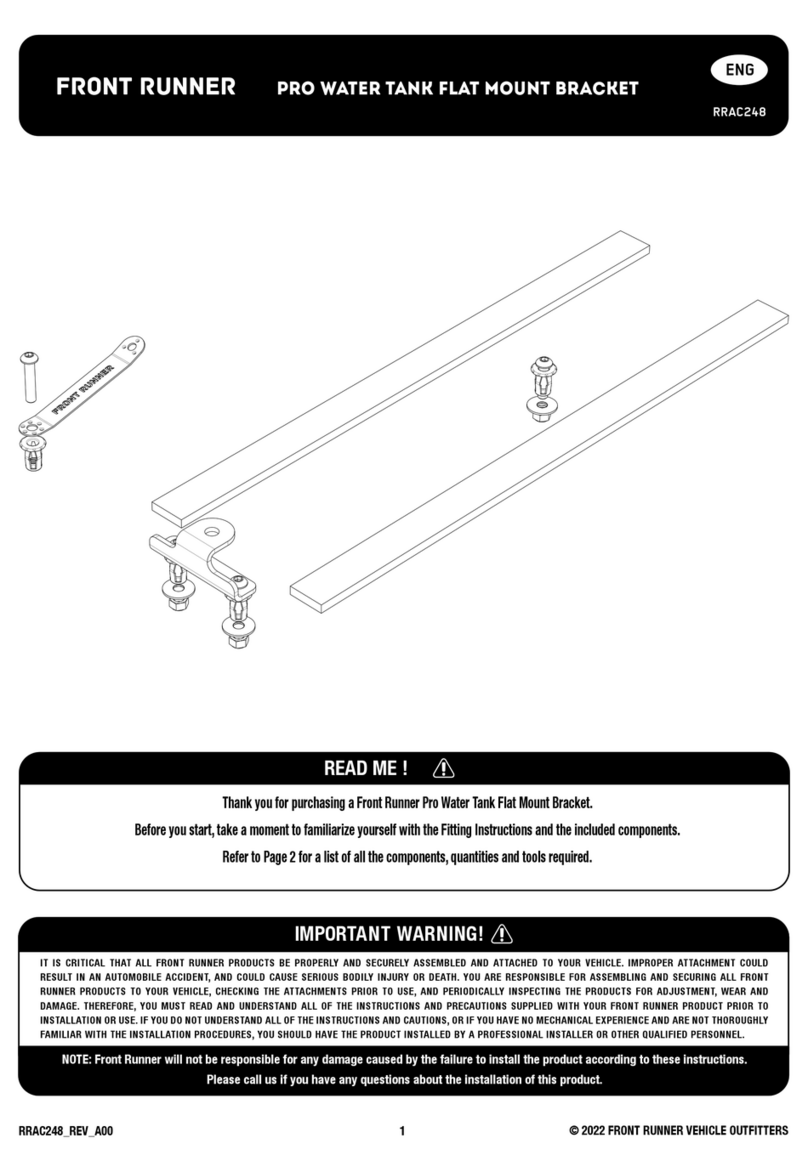
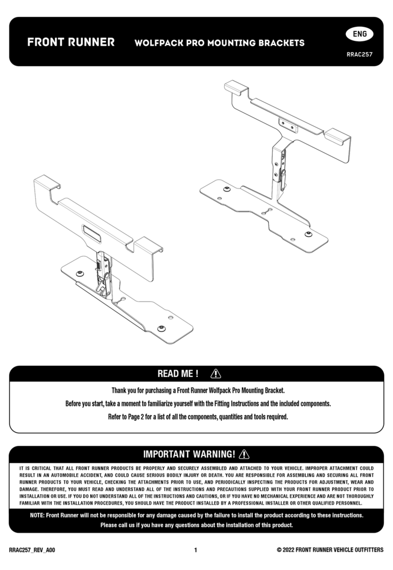
Front Runner Wolfpack Pro RRAC257 User manual

Front Runner

Front Runner Wolfpack Pro RRAC257 User manual

Front Runner FAMG001 User manual

Front Runner

Front Runner FAMG001 User manual

Front Runner LAMG003 User manual

Front Runner

Front Runner LAMG003 User manual
Front Runner LADD007 User manual

Front Runner

Front Runner LADD007 User manual

Front Runner SSAM009 User manual

Front Runner

Front Runner SSAM009 User manual

Front Runner BPTH007 User manual

Front Runner

Front Runner BPTH007 User manual

Front Runner PRO UNDER RACK TABLE bracket User manual

Front Runner

Front Runner PRO UNDER RACK TABLE bracket User manual

Front Runner SSDS111 User manual

Front Runner

Front Runner SSDS111 User manual

Front Runner SSAM008 User manual

Front Runner

Front Runner SSAM008 User manual

Front Runner SSLD001 User manual

Front Runner

Front Runner SSLD001 User manual

Front Runner RRAC120 User manual

Front Runner

Front Runner RRAC120 User manual

Front Runner LATF002 User manual

Front Runner

Front Runner LATF002 User manual

Front Runner LATF001 User manual

Front Runner

Front Runner LATF001 User manual

Front Runner FSLI023 User manual

Front Runner

Front Runner FSLI023 User manual

Front Runner RRAC248 User manual

Front Runner

Front Runner RRAC248 User manual
Front Runner KSTF003T User manual

Front Runner

Front Runner KSTF003T User manual

Front Runner TRCA004 User manual

Front Runner

Front Runner TRCA004 User manual

Front Runner TBRA020 User manual

Front Runner

Front Runner TBRA020 User manual

Front Runner TBRA034 User manual

Front Runner

Front Runner TBRA034 User manual

Front Runner FAJK007 User manual

Front Runner

Front Runner FAJK007 User manual

Front Runner PBTT002 User manual

Front Runner

Front Runner PBTT002 User manual

Front Runner Slimline II KRVA002T User manual

Front Runner

Front Runner Slimline II KRVA002T User manual

Front Runner SSDR003 User manual

Front Runner

Front Runner SSDR003 User manual

Front Runner RRAC190 User manual

Front Runner

Front Runner RRAC190 User manual

Popular Automobile Accessories manuals by other brands

TRUCKBOSS Flip Extension Install instructions

TRUCKBOSS

TRUCKBOSS Flip Extension Install instructions

Kenwood KCA-BT100 instruction manual

Kenwood

Kenwood KCA-BT100 instruction manual

Yakima BaseClip 133 quick start guide

Yakima

Yakima BaseClip 133 quick start guide

COMTRUK TC-098 installation manual

COMTRUK

COMTRUK TC-098 installation manual

Thetford 24571 installation instructions

Thetford

Thetford 24571 installation instructions

HydraBed Reel Lift Retrieval System installation guide

HydraBed

HydraBed Reel Lift Retrieval System installation guide

BETTY & BERTIE LUPIN manual

BETTY & BERTIE

BETTY & BERTIE LUPIN manual

Honeywell Thor VM1A user guide

Honeywell

Honeywell Thor VM1A user guide

ULTIMATE SPEED UAMM 12 B2 operating instructions

ULTIMATE SPEED

ULTIMATE SPEED UAMM 12 B2 operating instructions

Federal Signal Corporation CommCenter D1 Series Installation and service instructions

Federal Signal Corporation

Federal Signal Corporation CommCenter D1 Series Installation and service instructions

Leitner ACS ROOF ROOF FOR ACS FORGED / CLASSIC manual

Leitner

Leitner ACS ROOF ROOF FOR ACS FORGED / CLASSIC manual

Dometic Heki de Luxe installation manual

Dometic

Dometic Heki de Luxe installation manual

Fabtech FTS22068 installation instructions

Fabtech

Fabtech FTS22068 installation instructions

Lippert Components In-Wall Slide-Out Service manual

Lippert Components

Lippert Components In-Wall Slide-Out Service manual

DS Audio DS 003 instruction manual

DS Audio

DS Audio DS 003 instruction manual

Prorack K822 manual

Prorack

Prorack K822 manual

Axxess ASWC-TOY-LEX installation instructions

Axxess

Axxess ASWC-TOY-LEX installation instructions

Citadel TouchStar TS3000 user manual

Citadel

Citadel TouchStar TS3000 user manual

manuals.online logo
manuals.online logoBrands
  • About & Mission
  • Contact us
  • Privacy Policy
  • Terms and Conditions

Copyright 2025 Manuals.Online. All Rights Reserved.