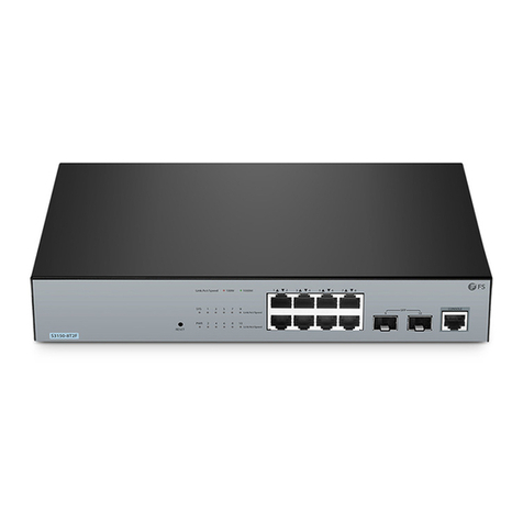
FS S1900-8T User manual

Introduction
S1900-8T
Thank you for choosing S1900-8T switch. This guide is designed to
familiarize you with the layout of the switch and describes how to
deploy the switch in your network.
Accessories
Grounding Cable x1
Expansion Tube x2
(Inner diameter: 2.5mm,
length: 25mm)
Power Adapter x1
Rubber Pad x4
Grounding Screw x1
M3 Screw x2
(M3*25mm)
1PWR 2 4 5 6 7 8
3
S1900-8T
1EN
V2.1
Quick Start Guide
Quick-Start Anleitung
Guide de Démarrage Rapide
ETHERNET UNMANAGED SWITCH
SWTCH ETHERNET NON GÉRÉ
ETHERNET UNMANAGED SWITCH
S1900-8T
1PWR 2 4 5 6 7 8
3
S1900-8T

Introduction
S1900-8T
Thank you for choosing S1900-8T switch. This guide is designed to
familiarize you with the layout of the switch and describes how to
deploy the switch in your network.
Accessories
Grounding Cable x1
Expansion Tube x2
(Inner diameter: 2.5mm,
length: 25mm)
Power Adapter x1
Rubber Pad x4
Grounding Screw x1
M3 Screw x2
(M3*25mm)
1PWR 2 4 5 6 7 8
3
S1900-8T
1EN
1PWR 2 4 5 6 7 8
3
S1900-8T
Front Panel
Back Panel Ports
Hardware Overview
PWR RJ45
Ports Description
RJ45 10/100/1000BASE-T ports for Ethernet connection
LEDs Status Description
PWR
RJ45
Green Switch is powered on.
Power supply is absent or abnormal.
10/100/1000BASE-T port is linked.
The RJ45 port is transmitting or receiving packets
at 10/100/1000Mbps.
O
Green
O Port is not linked.
Blinking Green
RJ45
54321
678
2 EN

1. Attach four rubber pads to the bottom.
2. Place the chassis on a desk.
1. Drill two suitable holes, press two expansion tubes into the two
holes respectively.
Mounting the Switch
Desk Mounting
Wall Mounting
1PWR 2 4 5 6 7 8
3
S1900-8T
4 EN
Back Panel
Site Environment:
Do notoperate itin an areathat exceeds an ambient
temperature of 40°C.
The installationsite must be free fromleaking or dripping
water, heavy dew, and humidity.
Ensure walland working platforms are well earthed.
The installation site must be well ventilated. Ensure that there is
Be sure that the switch is level and stable to avoid any
hazardous conditions.
Do notinstall the equipmentina dusty environment.
Installation Requirements
Before you begin the installation, make sure that you
have the following:
Desktop mounting: ESD bracelet (or ESD gloves)
Wall mounting: ESD bracelet(or ESD gloves), ladder, marker,
hammer drill, rubber hammer, screwdriver
54321
678
Power Supply
3EN

1. Attach four rubber pads to the bottom.
2. Place the chassis on a desk.
1. Drill two suitable holes, press two expansion tubes into the two
holes respectively.
Mounting the Switch
Desk Mounting
Wall Mounting
1PWR 2 4 5 6 7 8
3
S1900-8T
4 EN
2. Insert the screw into the expansion tube respectively.
3. Hang the switch on the two screws.
5EN

2. Insert the screw into the expansion tube respectively.
3. Hang the switch on the two screws.
5EN
4. Installation is completed.
1. Connect one end of the grounding cable to a proper earth ground,
such as the wall in which the switch is mounted.
2. Secure the grounding lug to the grounding point on the left side of
the switch with the washer and screws.
Grounding the Switch
CAUTION: The earth connection must not be removed unless all supply
connections have been disconnected.
6 EN
54321
6
7
8
1. Plug the DC power cord into the power port on the back of the
switch.
2. Connect the other end of the power adapter to an DC power source.
Connecting the Power
WARNING: Do not install power adapter while the power is on.
7EN

54321
6
7
8
1. Plug the DC power cord into the power port on the back of the
switch.
2. Connect the other end of the power adapter to an DC power source.
Connecting the Power
WARNING: Do not install power adapter while the power is on.
7EN
54321
6
7
8
Connecting the RJ45 Ports
1. Connect an Ethernet cable to the RJ45 port of a computer, printer,
network storage, or other network devices.
2. Connect the other end of the Ethernet cable to the RJ45 port of the
switch.
8 EN

54321
6
7
8
Connecting the RJ45 Ports
1. Connect an Ethernet cable to the RJ45 port of a computer, printer,
network storage, or other network devices.
2. Connect the other end of the Ethernet cable to the RJ45 port of the
switch.
8 EN

Einführung
S1900-8T
Vielen Dank, dass Sie sich für einen S1900-8T Switch entschieden
haben. Diese Anleitung soll Sie mit dem Aufbau des Switches vertraut
machen und beschreibt, wie Sie den Switch in Ihrem Netzwerk
einsetzen.
Zubehör
Erdungskabel x1
Expansionsrohr x2
(Innendurchmesser:
2,5 mm, Länge: 25 mm)
Netzadapter x1
Gummipad x4
Erdungsschraube x1
M3-Schraube x2
(M3*25mm)
1PWR 2 4 5 6 7 8
3
S1900-8T
10 DE
Support and Other Resources
Download https://www.fs.com/products_support.html
Help Center https://www.fs.com/service/fs_support.html
Contact Us https://www.fs.com/contact_us.html
Product Warranty
FS ensures our customers that any damage or faulty items due to our
you receive your goods. This excludes any custom made items or
tailored solutions.
Warranty: S1900-8T Switch enjoys 2 years limited warranty
against defect in materials or workmanship. For more details
about warranty, please check at
https://www.fs.com/policies/warranty.html
2
Return: If you want to return item(s), information on how to
return can be found at
https://www.fs.com/policies/day_return_policy.html
9EN

Einführung
S1900-8T
Vielen Dank, dass Sie sich für einen S1900-8T Switch entschieden
haben. Diese Anleitung soll Sie mit dem Aufbau des Switches vertraut
machen und beschreibt, wie Sie den Switch in Ihrem Netzwerk
einsetzen.
Zubehör
Erdungskabel x1
Expansionsrohr x2
(Innendurchmesser:
2,5 mm, Länge: 25 mm)
Netzadapter x1
Gummipad x4
Erdungsschraube x1
M3-Schraube x2
(M3*25mm)
1PWR 2 4 5 6 7 8
3
S1900-8T
10 DE

1PWR 2 4 5 6 7 8
3
S1900-8T
Vorderseite
Ports auf der Rückseite
Hardware-Übersicht
PWR RJ45
Ports Beschreibung
RJ45 10/100/1000BASE-T-Ports für Ethernet-Anschluss
LEDs Status Beschreibung
PWR
RJ45
Grün Der Switch ist eingeschaltet.
Die Stromversorgung ist nicht vorhanden oder abnormal.
10/100/1000BASE-T-Port ist verbunden.
Der RJ45-Port sendet oder empfängt Pakete mit
10/100/1000Mbps.
Aus
Grün
Aus Port ist nicht verbunden.
Blinkend Grün
RJ45
54321
678
11DE
Rückseite
54321
678
Stromversorgung
12 DE
Standortumgebung:
Betreiben Sie dasGerät nicht ineinem Bereich, der eine
Umgebungstemperatur von 40°C überschreitet.
Der Installationsort mussfrei vonaustretendemoder
tropfendem Wasser, starkem Tau und Feuchtigkeit sein.
Stellen Sie sicher, dass Wand und Arbeitsbühnengutgeerdetsind.
Der Aufstellungsort muss gut belüftet sein. Stellen Sie sicher, dass
um den Switch herum ein ausreichender Luftstrom vorhanden ist.
AchtenSie darauf, dass der Switch eben und stabil steht, um g
efährliche Bedingungen zu vermeiden.
Installieren Sie das Gerätnicht ineiner staubigenUmgebung.
Installationsvoraussetzungen
Bevor Sie mit der Installation beginnen, vergewissern
Sie sich, dass folgende Voraussetzungen erfüllt sind:
Tischmontage: ESD-Armband (oder ESD-Handschuhe)
Wandmontage: ESD-Armband (oder ESD-Handschuhe), Leiter,
Marker, Bohrhammer, Gummihammer, Schraubendreher

1. Bringen Sie vier Gummipads an der Unterseite an.
2. Stellen Sie das Gehäuse auf den Tisch.
1. Bohren Sie zwei geeignete Löcher, drücken Sie jeweils zwei
Expansionsrohre in die beiden Löcher.
Montage des Switches
Tischmontage
Wandmontage
1PWR 2 4 5 6 7 8
3
S1900-8T
13DE

Introduction
S1900-8T
Thank you for choosing S1900-8T switch. This guide is designed to
familiarize you with the layout of the switch and describes how to
deploy the switch in your network.
Accessories
Grounding Cable x1
Expansion Tube x2
(Inner diameter: 2.5mm,
length: 25mm)
Power Adapter x1
Rubber Pad x4
Grounding Screw x1
M3 Screw x2
(M3*25mm)
1PWR 2 4 5 6 7 8
3
S1900-8T
1EN
2. Setzen Sie die Schraube jeweils in das Dehnungsrohr ein.
3. Hängen Sie den Switch an die beiden Schrauben.
14 DE
4. Die Installation ist abgeschlossen.
1. Schließen Sie ein Ende des Erdungskabels an eine geeignete
Erdung an, z. B. an die Wand, in der der Switch montiert ist.
2. Befestigen Sie die Erdungslasche mit der Unterlegscheibe und den
Schrauben am Erdungspunkt an der linken Seite des Switches.
Erdung des Switches
ACHTUNG: Der Erdungsanschluss darf erst dann entfernt werden, wenn
alle Versorgungsanschlüsse getrennt wurden.
15DE

Introduction
S1900-8T
Thank you for choosing S1900-8T switch. This guide is designed to
familiarize you with the layout of the switch and describes how to
deploy the switch in your network.
Accessories
Grounding Cable x1
Expansion Tube x2
(Inner diameter: 2.5mm,
length: 25mm)
Power Adapter x1
Rubber Pad x4
Grounding Screw x1
M3 Screw x2
(M3*25mm)
1PWR 2 4 5 6 7 8
3
S1900-8T
1EN
1PWR 2 4 5 6 7 8
3
S1900-8T
Front Panel
Back Panel Ports
Hardware Overview
PWR RJ45
Ports Description
RJ45 10/100/1000BASE-T ports for Ethernet connection
LEDs Status Description
PWR
RJ45
Green Switch is powered on.
Power supply is absent or abnormal.
10/100/1000BASE-T port is linked.
The RJ45 port is transmitting or receiving packets
at 10/100/1000Mbps.
O
Green
O Port is not linked.
Blinking Green
RJ45
54321
678
2 EN
4. Die Installation ist abgeschlossen.
1. Schließen Sie ein Ende des Erdungskabels an eine geeignete
Erdung an, z. B. an die Wand, in der der Switch montiert ist.
2. Befestigen Sie die Erdungslasche mit der Unterlegscheibe und den
Schrauben am Erdungspunkt an der linken Seite des Switches.
Erdung des Switches
ACHTUNG: Der Erdungsanschluss darf erst dann entfernt werden, wenn
alle Versorgungsanschlüsse getrennt wurden.
15DE
54321
6
7
8
1. Stecken Sie das DC-Netzkabel in den Netzanschluss auf der
Rückseite des Switches.
2. Schließen Sie das andere Ende des Netzteils an eine
Gleichstromquelle an.
Anschließen der Stromversorgung
WARNUNG: Installieren Sie den Netzadapter nicht, während das Gerät
eingeschaltet ist.
16 DE

1PWR 2 4 5 6 7 8
3
S1900-8T
Front Panel
Back Panel Ports
Hardware Overview
PWR RJ45
Ports Description
RJ45 10/100/1000BASE-T ports for Ethernet connection
LEDs Status Description
PWR
RJ45
Green Switch is powered on.
Power supply is absent or abnormal.
10/100/1000BASE-T port is linked.
The RJ45 port is transmitting or receiving packets
at 10/100/1000Mbps.
O
Green
O Port is not linked.
Blinking Green
RJ45
54321
678
2 EN
54321
6
7
8
1. Stecken Sie das DC-Netzkabel in den Netzanschluss auf der
Rückseite des Switches.
2. Schließen Sie das andere Ende des Netzteils an eine
Gleichstromquelle an.
Anschließen der Stromversorgung
WARNUNG: Installieren Sie den Netzadapter nicht, während das Gerät
eingeschaltet ist.
16 DE
54321
6
7
8
Anschließen der RJ45-Ports
1. Schließen Sie ein Ethernet-Kabel an den RJ45-Anschluss eines
Computers, Druckers, Netzwerkspeichers oder anderer
Netzwerkgeräte an.
2. Schließen Sie das andere Ende des Ethernet-Kabels an den
RJ45-Anschluss des Switches an.
17DE

1. Attach four rubber pads to the bottom.
2. Place the chassis on a desk.
1. Drill two suitable holes, press two expansion tubes into the two
holes respectively.
Mounting the Switch
Desk Mounting
Wall Mounting
1PWR 2 4 5 6 7 8
3
S1900-8T
4 EN
2. Insert the screw into the expansion tube respectively.
3. Hang the switch on the two screws.
5EN
Introduction
S1900-8T
Merci d'avoir choisi le switch S1900-8T. Ce guide est conçu pour que
vous puissiez vous familiariser avec la conguration du switch et
indique comment procéder à son déploiement.
1PWR 2 4 5 6 7 8
3
S1900-8T
19FR
Accessoires
Câble de Mise à Terre x1
Tube de dilatation x2
(Diamètre intérieur : 2,5mm,
longueur : 25mm)
Adaptateur
d'Alimentation x1
Coussin en
Caoutchouc x4
Vis de Mise à Terre x1
Vis M3 x2
(M3*25mm)
18 DE
Support und andere Ressourcen
Download
Hilfecenter https://www.fs.com/de/service/fs_support.html
https://www.fs.com/de/products_support.html
Kontakt https://www.fs.com/de/contact_us.html
Produktgarantie
FS garantiert seinen Kunden, dass wir bei Schäden oder fehlerhaften
Artikeln, die auf unsere Verarbeitung zurückzuführen sind, eine
kostenlose Rücksendung innerhalb von 30 Tagen ab demTag, an dem
Sie Ihre Ware erhalten haben, vornehmen. Dies gilt nicht für
Sonderanfertigungen oder maßgeschneiderte Lösungen.
Garantie: Für den S1900-8T Switch gilt eine 2-jährige
eingeschränkte Garantie gegen Material- und Verarbeitungsfe-
https://www.fs.com/de/policies/warranty.html
2
Rückgabe: Wenn Sie einen oder mehrere Artikel zurückgeben
https://www.fs.com/de/policies/day_return_policy.html

2. Insert the screw into the expansion tube respectively.
3. Hang the switch on the two screws.
5EN
4. Installation is completed.
1. Connect one end of the grounding cable to a proper earth ground,
such as the wall in which the switch is mounted.
2. Secure the grounding lug to the grounding point on the left side of
the switch with the washer and screws.
Grounding the Switch
CAUTION: The earth connection must not be removed unless all supply
connections have been disconnected.
6 EN
Introduction
S1900-8T
Merci d'avoir choisi le switch S1900-8T. Ce guide est conçu pour que
vous puissiez vous familiariser avec la conguration du switch et
indique comment procéder à son déploiement.
1PWR 2 4 5 6 7 8
3
S1900-8T
19FR
Accessoires
Câble de Mise à Terre x1
Tube de dilatation x2
(Diamètre intérieur : 2,5mm,
longueur : 25mm)
Adaptateur
d'Alimentation x1
Coussin en
Caoutchouc x4
Vis de Mise à Terre x1
Vis M3 x2
(M3*25mm)
1PWR 2 4 5 6 7 8
3
S1900-8T
Panneau Frontal
Port du Panneau Arrière
Aperçu du Matériel
PWR RJ45
Port Description
RJ45 Ports 10/100/1000BASE-T pour connexion Ethernet
LEDs Statut Description
PWR
RJ45
Vert Le switch est sous tension.
L'alimentation électrique est absente ou anormale.
Le port 10/100/1000BASE-T est relié.
Le port RJ45 transmet ou reçoit des paquets à
10/100/1000Mbps.
Éteint
Vert
Éteint Le port n'est pas relié.
Vert Clignotan
RJ45
54321
678
20 FR
Table of contents
Languages:
Other FS Switch manuals

FS
FS S5850-24S2C-DC User manual

FS
FS S3150-8T2FP User manual
FS
FS N Series User manual

FS
FS S3700-24T4F Instruction Manual

FS
FS S2800S Series User manual

FS
FS Fiberstore S8050-20Q4C User manual
FS
FS N5860 Series User manual
FS
FS S5850-24S2Q User manual

FS
FS S3900 Series User manual

FS
FS S3910 Series User manual
Popular Switch manuals by other brands

Hirschmann
Hirschmann SPIDER 8TX-PRO Description and operation instructions

Allied Telesis
Allied Telesis C613-02013-00 user guide

ZyXEL Communications
ZyXEL Communications ES-2048 user guide

Matrix Switch Corporation
Matrix Switch Corporation MSC-TXD44L product manual

CYP
CYP MA-U42 Operation manual

Pfannenberg
Pfannenberg PF H operating instructions