manuals.online logo
Brands
  1. Home
  2. •
  3. Brands
  4. •
  5. Furuno
  6. •
  7. Marine Equipment
  8. •
  9. Furuno FI-501 User manual

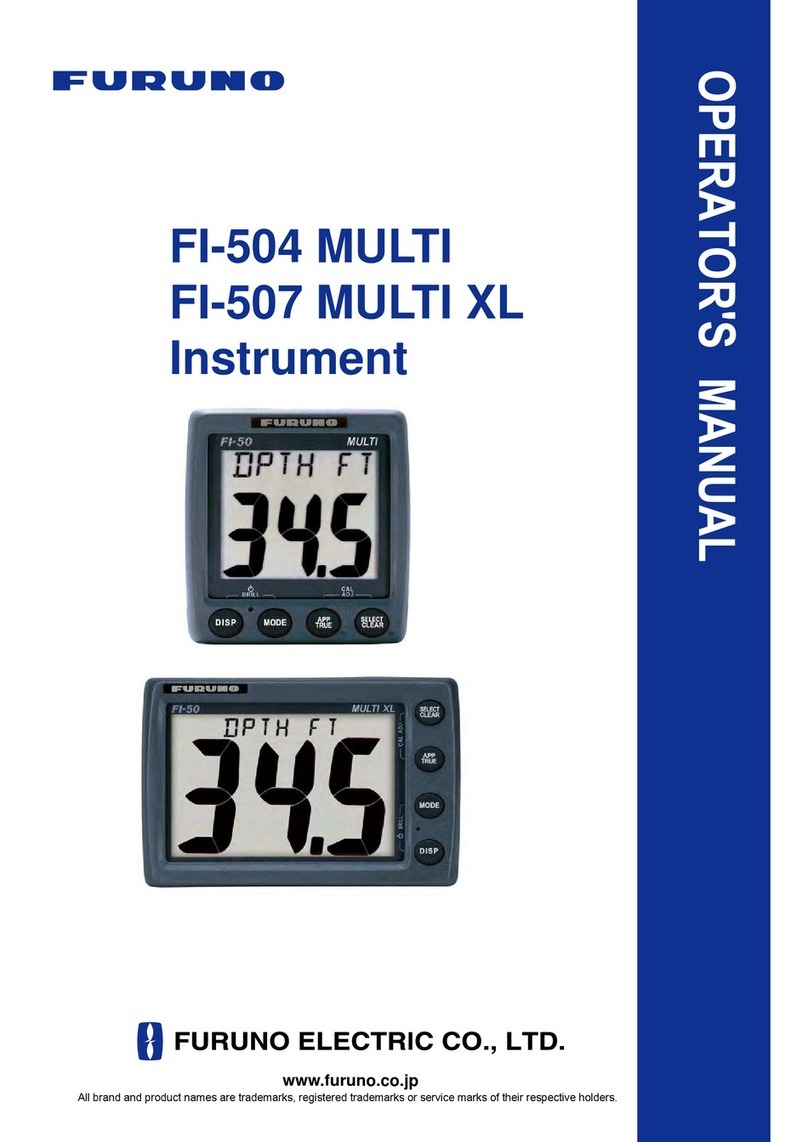
Furuno FI-501 User manual

Precision Instrumentation for Safeand Comfortable Boating
The FURUNO FI-50 Navigation Instrument Series are professionally
designed to meet the needs of all sailing and power boat vessels.
These instruments provide a wide variety of precise information,
even under the harshest conditions, enhancing your safety at sea.
Each easy-to-use display unit utilizes standard CAN bus network
connectors and cabling. Data from each component may be fully
integrated with any NavNet 3D or other CAN bus system providing
an easy “Plug and Play” installation.
s
Bright backlit displays with wide viewing angles
s
Auto-Backlighting feature minimizes power consumption
s
CAN bus interface offers “Plug and Play” networking
s
Easy installation with hole-saw flush-mount design
s
Ideal for mast or bulkhead mounting configurations
s
White face “F1 Style” gauges provide maximum contrast
and visibility
s
Latest Organic Light Emitting Diode (OLED) Backlighting
Technology reduces power consumption
WIND
FI-501
™
™
-
-
-
-
-
-
-
-
-
™
-
-
™
™
™
™
™
™
™
™
™
™
-
-
-
-
™
-
-
-
-
-
-
-
-
-
-
-
-
-
-
-
-
-
-
-
-
-
-
-
-
-
-
-
-
-
-
CH WIND
FI-502
™
™
-
-
-
-
-
-
-
-
-
™
-
-
™
™
™
™
™
™
™
™
™
™
-
-
-
-
™
-
-
-
-
-
-
-
-
-
-
-
-
-
-
-
-
-
-
-
-
-
-
-
-
-
-
-
-
-
-
MULTI
FI-504
™
-
™
™
™
™
™
™
™
™
™
™
™
™
™
™
™
™
™
™
™
™
™
™
™
™
™
™
™
™
™
™
-
™
™
™
™
™
™
™
™
™
™
™
™
™
™
™
™
™
™
™
™
™
™
™
™
™
™
MULTI XL
FI-507
™
-
™
™
™
™
™
™
™
™
™
™
™
™
™
™
™
™
™
™
™
™
™
™
™
™
™
™
™
™
™
™
-
™
™
™
™
™
™
™
™
™
™
™
™
™
™
™
™
™
™
™
™
™
™
™
™
™
™
COURSE
PILOT
FI-505
™
-
-
-
-
-
-
-
-
-
-
-
-
-
-
-
-
-
-
-
-
-
-
-
-
™
™
™
-
™
-
-
™
-
-
-
-
-
-
-
-
-
-
-
-
-
-
-
-
-
-
-
-
-
-
-
-
-
-
RUDDER
FI-506
™
-
-
-
-
-
-
-
-
-
-
-
-
-
-
-
-
-
-
-
-
-
-
-
-
-
-
-
-
-
-
-
-
-
-
-
-
-
-
-
-
-
-
-
-
-
-
-
-
-
-
-
-
-
-
™
-
-
-
DIGITAL
FI-503
™
-
™
™
™
™
™
™
™
™
™
™
™
™
™
™
™
™
™
™
™
™
™
™
-
-
-
-
-
-
-
-
-
-
-
-
-
-
-
-
-
-
-
™
™
-
-
™
™
™
™
™
™
™
™
-
-
-
-
Instruments
FI-501/502/503/504/505/506
0.3 kg 0.7 lb
Depth/Speed/Temp Sensor
DST-800 (Option)
0.9 kg 2.0 lb
Junction Box
FI-5002(Option)
0.3 kg 0.7 lb
Wind Transducer
FI-5001
0.3 kg 0.7 lb
FI-5001L
0.4 kg 0.9 lb
ø290
ø130
4–ø5
7.5
0.3"
517 20.4
"
(30 1.2
"
)
237 9.3
"
76
3.0
"
97
3.8
"
372 14.6
"
70 2.8
"
55
2.2"
40 1.6"
50 2.0"
80 3.1"
2–ø5
52
2.0
"
200 7.9
"
220 8.7
"
84 3.3
"
ø75 2.94
"
124 4.87
"
14
0.57
"
5
0.19
"
ø75 2.94
"
www.furuno.com
Port
CAN bus ×2
WIND ×1
Depth
Current depth
Shallow alarm threshold
Deep alarm threshold
Anchor shallow alarm threshold
Anchor deep alarm threshold
Speed
STW (Speed through water)
SOG (Speed over ground)
Maximum speed
Average speed
VMG to windward
Log (0 – 99999nm)
Trip (0.01 – 999nm)
Wind
Apparent wind speed
Apparent wind angle
True wind speed
True wind angle
Beaufort scale angle
Maximum wind speed
Maximum true wind speed alarm
Low true wind speed alarm
High apparent wind angle alarm
Low apparent wind angle alarm
Ground wind direction
Heading
Heading
Average heading
Locked heading
Heading on next tack
COG (Course over ground)
CMG (Course made good)
DMG (Distance made good)
ROT (Rate of turn)
Navigation
Bearing to waypoint
Distance to waypoint
Cross Track Error and error steer bar
Target waypoint name
Target waypoint number
Latitude
Longitude
GPS satellite status
Roll
Pitching
SOG
Environment
Battery voltage
Battery voltage alarm
Date and time
Water temperature
(two decimal points)
Air temperature
Pressure
Humidity
Wind chill temperature
Dew point
Timer
Count up timer
Count down timer
Autopilot
Rudder angle
Engine
Fuel information
Fuel consumption
Engine RPM
FI-507
0.5 kg 1.1 lb
Flush mount
Flush mount
111 4.3"
ø89
39 1.5"
17 0.7"
10
0.4"
125 4.9"
60 2.4"
194 7.6"
4- ø3.5 183 7.2"
113 4.4"
60 2.4"
173 6.8"
183 7.2"
4- R5
CAN bus connector
Surface mount
115 4.5"
42.5
1.7" 51.5
2.0"
175 6.9"
4- ø3.5 145 5.7"
160 6.3"
ø89
23
0.9"
26
1.0"
90 3.5"
45 1.8"
60 2.4"
ø90
CAN bus connector
108 4.3"
118 4.6"
113 4.4"
60 2.4"
115 4.5"
110 4.3"
49 1.9"
26 1.0"
24 0.9"
ø89
2–ø3.5
45
1.8"
44.6
1.8"
60
2.4"
ø90 Hole Saw
CAN bus connector
Wind sensor connector
(FI-501/502 only)
CAN bus connector
Wind sensor connector
(FI-501/502 only)
Surface mount
125 4.9"
129 5.1"
49 1.9"
10
0.4" 17 0.7"
111 4.4"
ø89
Cutout for
flush mount
Cutout for
surface mount
Cutout for
flush mount
Cutout for
surface mount
(30 1.2") 865 34.1"
ø290
7.5
0.3"
55
2.2"
80 3.1"
50 2.0"
40 1.6"
350 13.8"
76
3.0"
210
8.3"
720 28.3" 145 5.7"
70 2.8"
ø130
4–ø5
TRADEMARK REGISTERED
SPECIFICATIONS SUBJECT TO CHANGE WITHOUT NOTICE
09025U Printed in Japan
Catalogue No. M-1542d
FURUNO U.S.A., INC.
Camas, Washington, U.S.A.
Phone: +1 360-834-9300
Fax: +1 360-834-9400
FURUNO ELECTRIC CO., LTD.
Nishinomiya, Hyogo, Japan
Phone: +81 (0)798 65-2111
Fax: +81 (0)798 65-4200, 66-4622
FURUNO (UK) LIMITED
Havant, Hampshire, U.K.
Phone: +44 23 9244 1000
Fax: +44 23 9248 4316
FURUNO FRANCE S.A.S.
Bordeaux-Mérignac, France
Phone: +33 5 56 13 48 00
Fax: +33 5 56 13 48 01
FURUNO ESPAÑA S.A.
Madrid, Spain
Phone: +34 91-725-90-88
Fax: +34 91-725-98-97
FURUNO DANMARK AS
Hvidovre, Denmark
Phone: +45 36 77 45 00
Fax: +45 36 77 45 01
FURUNO NORGE A/S
Ålesund, Norway
Phone: +47 70 102950
Fax: +47 70 102951
FURUNO SVERIGE AB
Västra Frölunda, Sweden
Phone: +46 31-7098940
Fax: +46 31-497093
FURUNO FINLAND OY
Espoo, Finland
Phone: +358 9 4355 670
Fax: +358 9 4355 6710
FURUNO POLSKA Sp. Z o.o.
Gdynia, Poland
Phone: +48 58 669 02 20
Fax: +48 58 669 02 21
FURUNO DEUTSCHLAND GmbH
Rellingen, Germany
Phone: +49 4101 838 0
Fax: +49 4101 838 111
FURUNO EURUS LLC
St. Petersburg, Russian Federation
Phone: +7 812 767 15 92
Fax: +7 812 766 55 52
Sensors and Accessories (Option)
The units are designed to match the
NavNet 3D series and other navigation
equipment. The
“
Plug and Play”system
utilizes CAN bus interface protocol, which
gives the system exceptional interface
ability.
The FI-50 Series utilize high-contrast, backlit LCD displays for
superior viewing even in direct sunlight. Each unit features an
easy-to-read display and 4 simple programming buttons for
operation. The function for each key and combination are printed
directly on the front panel.
The FI-50 series of instruments minimize power consumption
by turning off the backlight during the daytime. Sensors on
the front panel measure ambient lighting conditions and
adjust the on/off condition of the display backlighting
accordingly.
Data displayed
•
Apparent and true wind speed
•
Apparent and true wind angle
•
Maximum true wind speed
•
MAX/LOW true wind speed alarm
•
High/Low apparent wind angle alarm
•
Beaufort wind speed
•
VMG to windward
The FI-503 displays critical digital navigation
data such as depth, speed, temp, and
weather data on a 3-way split screen.
Data displayed
1•
Current depth
•
Shallow/deep alarm
•
Shallow/deep anchor alarm
•
Wind angle
•
High/Low apparent wind angle
2•
Boat speed
•
MAX/AVG STW
•
SOG
•
MAX/AVG SOG
•
VMG to windward
•
Wind
speed
•
MAX true wind
•
MAX/LOW true wind
speed alarm
•
Beaufort wind speed
3•
LOG
•
Trip
•
Count up/down timer
•
Water
temperature
•
Air temperature
•
Air pressure
•
Humidity
•
Wind chill temperature
•
Dew point
Apparent and True Wind Angle are displayed
in both analog and digital format when
connected to the FI-5001/5001L or other
CAN bus wind measurement devices.
The FI-502 provides detailed and precise
wind bearing measurements from 60 Port to
60 Starboard, an important range for Close
Hauled (CH) points of sail.
The FI-504 and FI-507 feature large digital displays with
easy-to-read characters presenting all of the information
available in the CAN bus network*. Alternating data display
mode switches the user-selected information in 3-second
intervals.
Data displayed
•
Displays all information on the FI-50 series*
•
NAVIGATION
(Bearing/distance to WPT, XTE, WPT number/name, L/L, Satellites
tracked, Roll & Pitch)
•
ENVIRONMENT (Battery voltage, Time & Date)
•
ENGINE (Trip fuel used, Fuel consumption, Engine RPM)
*Except ROT. ROT can be displayed on FI-505.
The FI-505 provides a digital compass
readout with an analog “Off Course”
needle that greatly assists the
helmsman in maintaining a desired
course. When connected to satellite
compass, smooth and precise ROT
(Rate Of Turn) of the boat is shown
with the analog needle. The needle
can also be used to verify autopilot
steering performance.
Data displayed
•
Current heading
•
Locked heading
•
Average heading
•
Course over ground
•
ROT
When connected to an autopilot,
the analog FI-506 Rudder Angle
Display shows precise rudder
angle information.
Data displayed
•
Rudder angle
FI-503 FI-504 FI-507 FI-505 FI-506FI-501
Depth/Speed/Temp Sensor
DST-800
Frequency: 235 kHz
Cable: 6 m
Wind Transducer
FI-5001/FI-5001L
Power supply: 12 VDC, less than 40 mA
Transducer cable: 30/50 m
Junction Box
FI-5002
CAN bus backbone x 2 ports
CAN bus x 6 ports
Power supply: 12 VDC, less than 2A
FI-502
DIGITAL MULTI / MULTI XL COURSE PILOT RUDDERWIND CH WIND
Specifications of FI-50 series
Easy to install
Easy to Read with Silver Bright LCD Display
FI-503
DIGITAL
FI-504
MULTI
Operational guide description on the front panel
22
mm
41
mm
22
mm
DaytimeSunset or after
Back Light
Turns On
Back Light
Turns Off
Automatic Backlight Adjustment
Automatic Detection
Display: Analog and digital LCD (FI-501, 502, 505)
Digital LCD (FI-503, 504, 507)
Analog (FI-506)
Power supply: 12 VDC, less than 0.1 A
Temperature: –15°C to +55°C
Waterproofing: IP56
Surface mount installation Flush mount installation
with optional front panel
Surface Mount the displays with a hole saw and install 4 screws
under the front bezel. Installations are easy and clean with a finished
appearance (1"(26mm)bulkhead protrusion)
Optional “Low Profile” Flush Mounting front panels provide
a cosmetic match to NN3D Displays and a custom console
appearance (0.4"(10mm)bulkhead protrusion)
1 DIN type 1.5 DIN type
FI-5001 FI-5001L
Wind Transducer
Wind Transducer
12 V
Basic Configurations
Sail Boat
Power Boat
System Configurations
Wind Transducer
12 V
DigitalWind Multi
12 V
Depth/Speed/Temp
Sensor
Depth/Speed/Temp
Sensor
Depth/Speed/Temp
Sensor
WAAS/GPS
Antenna
Wind Multi Multi XL
Multi XL
Digital
Network Radar Sensor
Navnet 3D
Multi Function
Display
Wind Transducer
Transducer
Depth/Speed/Temp
Sensor
Wind MultiDigital
Network Radar Sensor
Navnet 3D
Multi Function
Display
DigitalWind
CAN bus
Ethernet
others
Wind Transducer
FI-501 FI-503
JUNCTION
BOX
MULTI FUNCTION
DISPLAY
DFF1
HUB
* 12V power supplied from NavNet 3D
Satellite Compass Weather Station
Junction Box
WAAS/GPS
Antenna
Junction Box
Weather Station
Precision Instrumentation for Safeand Comfortable Boating
The FURUNO FI-50 Navigation Instrument Series are professionally
designed to meet the needs of all sailing and power boat vessels.
These instruments provide a wide variety of precise information,
even under the harshest conditions, enhancing your safety at sea.
Each easy-to-use display unit utilizes standard CAN bus network
connectors and cabling. Data from each component may be fully
integrated with any NavNet 3D or other CAN bus system providing
an easy “Plug and Play” installation.
s
Bright backlit displays with wide viewing angles
s
Auto-Backlighting feature minimizes power consumption
s
CAN bus interface offers “Plug and Play” networking
s
Easy installation with hole-saw flush-mount design
s
Ideal for mast or bulkhead mounting configurations
s
White face “F1 Style” gauges provide maximum contrast
and visibility
s
Latest Organic Light Emitting Diode (OLED) Backlighting
Technology reduces power consumption
WIND
FI-501
™
™
-
-
-
-
-
-
-
-
-
™
-
-
™
™
™
™
™
™
™
™
™
™
-
-
-
-
™
-
-
-
-
-
-
-
-
-
-
-
-
-
-
-
-
-
-
-
-
-
-
-
-
-
-
-
-
-
-
CH WIND
FI-502
™
™
-
-
-
-
-
-
-
-
-
™
-
-
™
™
™
™
™
™
™
™
™
™
-
-
-
-
™
-
-
-
-
-
-
-
-
-
-
-
-
-
-
-
-
-
-
-
-
-
-
-
-
-
-
-
-
-
-
MULTI
FI-504
™
-
™
™
™
™
™
™
™
™
™
™
™
™
™
™
™
™
™
™
™
™
™
™
™
™
™
™
™
™
™
™
-
™
™
™
™
™
™
™
™
™
™
™
™
™
™
™
™
™
™
™
™
™
™
™
™
™
™
MULTI XL
FI-507
™
-
™
™
™
™
™
™
™
™
™
™
™
™
™
™
™
™
™
™
™
™
™
™
™
™
™
™
™
™
™
™
-
™
™
™
™
™
™
™
™
™
™
™
™
™
™
™
™
™
™
™
™
™
™
™
™
™
™
COURSE
PILOT
FI-505
™
-
-
-
-
-
-
-
-
-
-
-
-
-
-
-
-
-
-
-
-
-
-
-
-
™
™
™
-
™
-
-
™
-
-
-
-
-
-
-
-
-
-
-
-
-
-
-
-
-
-
-
-
-
-
-
-
-
-
RUDDER
FI-506
™
-
-
-
-
-
-
-
-
-
-
-
-
-
-
-
-
-
-
-
-
-
-
-
-
-
-
-
-
-
-
-
-
-
-
-
-
-
-
-
-
-
-
-
-
-
-
-
-
-
-
-
-
-
-
™
-
-
-
DIGITAL
FI-503
™
-
™
™
™
™
™
™
™
™
™
™
™
™
™
™
™
™
™
™
™
™
™
™
-
-
-
-
-
-
-
-
-
-
-
-
-
-
-
-
-
-
-
™
™
-
-
™
™
™
™
™
™
™
™
-
-
-
-
Instruments
FI-501/502/503/504/505/506
0.3 kg 0.7 lb
Depth/Speed/Temp Sensor
DST-800 (Option)
0.9 kg 2.0 lb
Junction Box
FI-5002(Option)
0.3 kg 0.7 lb
Wind Transducer
FI-5001
0.3 kg 0.7 lb
FI-5001L
0.4 kg 0.9 lb
ø290
ø130
4–ø5
7.5
0.3"
517 20.4
"
(30 1.2
"
)
237 9.3
"
76
3.0
"
97
3.8
"
372 14.6
"
70 2.8
"
55
2.2"
40 1.6"
50 2.0"
80 3.1"
2–ø5
52
2.0
"
200 7.9
"
220 8.7
"
84 3.3
"
ø75 2.94
"
124 4.87
"
14
0.57
"
5
0.19
"
ø75 2.94
"
www.furuno.com
Port
CAN bus ×2
WIND ×1
Depth
Current depth
Shallow alarm threshold
Deep alarm threshold
Anchor shallow alarm threshold
Anchor deep alarm threshold
Speed
STW (Speed through water)
SOG (Speed over ground)
Maximum speed
Average speed
VMG to windward
Log (0 – 99999nm)
Trip (0.01 – 999nm)
Wind
Apparent wind speed
Apparent wind angle
True wind speed
True wind angle
Beaufort scale angle
Maximum wind speed
Maximum true wind speed alarm
Low true wind speed alarm
High apparent wind angle alarm
Low apparent wind angle alarm
Ground wind direction
Heading
Heading
Average heading
Locked heading
Heading on next tack
COG (Course over ground)
CMG (Course made good)
DMG (Distance made good)
ROT (Rate of turn)
Navigation
Bearing to waypoint
Distance to waypoint
Cross Track Error and error steer bar
Target waypoint name
Target waypoint number
Latitude
Longitude
GPS satellite status
Roll
Pitching
SOG
Environment
Battery voltage
Battery voltage alarm
Date and time
Water temperature
(two decimal points)
Air temperature
Pressure
Humidity
Wind chill temperature
Dew point
Timer
Count up timer
Count down timer
Autopilot
Rudder angle
Engine
Fuel information
Fuel consumption
Engine RPM
FI-507
0.5 kg 1.1 lb
Flush mount
Flush mount
111 4.3"
ø89
39 1.5"
17 0.7"
10
0.4"
125 4.9"
60 2.4"
194 7.6"
4- ø3.5 183 7.2"
113 4.4"
60 2.4"
173 6.8"
183 7.2"
4- R5
CAN bus connector
Surface mount
115 4.5"
42.5
1.7" 51.5
2.0"
175 6.9"
4- ø3.5 145 5.7"
160 6.3"
ø89
23
0.9"
26
1.0"
90 3.5"
45 1.8"
60 2.4"
ø90
CAN bus connector
108 4.3"
118 4.6"
113 4.4"
60 2.4"
115 4.5"
110 4.3"
49 1.9"
26 1.0"
24 0.9"
ø89
2–ø3.5
45
1.8"
44.6
1.8"
60
2.4"
ø90 Hole Saw
CAN bus connector
Wind sensor connector
(FI-501/502 only)
CAN bus connector
Wind sensor connector
(FI-501/502 only)
Surface mount
125 4.9"
129 5.1"
49 1.9"
10
0.4" 17 0.7"
111 4.4"
ø89
Cutout for
flush mount
Cutout for
surface mount
Cutout for
flush mount
Cutout for
surface mount
(30 1.2") 865 34.1"
ø290
7.5
0.3"
55
2.2"
80 3.1"
50 2.0"
40 1.6"
350 13.8"
76
3.0"
210
8.3"
720 28.3" 145 5.7"
70 2.8"
ø130
4–ø5
TRADEMARK REGISTERED
SPECIFICATIONS SUBJECT TO CHANGE WITHOUT NOTICE
09025U Printed in Japan
Catalogue No. M-1542d
FURUNO U.S.A., INC.
Camas, Washington, U.S.A.
Phone: +1 360-834-9300
Fax: +1 360-834-9400
FURUNO ELECTRIC CO., LTD.
Nishinomiya, Hyogo, Japan
Phone: +81 (0)798 65-2111
Fax: +81 (0)798 65-4200, 66-4622
FURUNO (UK) LIMITED
Havant, Hampshire, U.K.
Phone: +44 23 9244 1000
Fax: +44 23 9248 4316
FURUNO FRANCE S.A.S.
Bordeaux-Mérignac, France
Phone: +33 5 56 13 48 00
Fax: +33 5 56 13 48 01
FURUNO ESPAÑA S.A.
Madrid, Spain
Phone: +34 91-725-90-88
Fax: +34 91-725-98-97
FURUNO DANMARK AS
Hvidovre, Denmark
Phone: +45 36 77 45 00
Fax: +45 36 77 45 01
FURUNO NORGE A/S
Ålesund, Norway
Phone: +47 70 102950
Fax: +47 70 102951
FURUNO SVERIGE AB
Västra Frölunda, Sweden
Phone: +46 31-7098940
Fax: +46 31-497093
FURUNO FINLAND OY
Espoo, Finland
Phone: +358 9 4355 670
Fax: +358 9 4355 6710
FURUNO POLSKA Sp. Z o.o.
Gdynia, Poland
Phone: +48 58 669 02 20
Fax: +48 58 669 02 21
FURUNO DEUTSCHLAND GmbH
Rellingen, Germany
Phone: +49 4101 838 0
Fax: +49 4101 838 111
FURUNO EURUS LLC
St. Petersburg, Russian Federation
Phone: +7 812 767 15 92
Fax: +7 812 766 55 52
Sensors and Accessories (Option)
The units are designed to match the
NavNet 3D series and other navigation
equipment. The
“
Plug and Play”system
utilizes CAN bus interface protocol, which
gives the system exceptional interface
ability.
The FI-50 Series utilize high-contrast, backlit LCD displays for
superior viewing even in direct sunlight. Each unit features an
easy-to-read display and 4 simple programming buttons for
operation. The function for each key and combination are printed
directly on the front panel.
The FI-50 series of instruments minimize power consumption
by turning off the backlight during the daytime. Sensors on
the front panel measure ambient lighting conditions and
adjust the on/off condition of the display backlighting
accordingly.
Data displayed
•
Apparent and true wind speed
•
Apparent and true wind angle
•
Maximum true wind speed
•
MAX/LOW true wind speed alarm
•
High/Low apparent wind angle alarm
•
Beaufort wind speed
•
VMG to windward
The FI-503 displays critical digital navigation
data such as depth, speed, temp, and
weather data on a 3-way split screen.
Data displayed
1•
Current depth
•
Shallow/deep alarm
•
Shallow/deep anchor alarm
•
Wind angle
•
High/Low apparent wind angle
2•
Boat speed
•
MAX/AVG STW
•
SOG
•
MAX/AVG SOG
•
VMG to windward
•
Wind
speed
•
MAX true wind
•
MAX/LOW true wind
speed alarm
•
Beaufort wind speed
3•
LOG
•
Trip
•
Count up/down timer
•
Water
temperature
•
Air temperature
•
Air pressure
•
Humidity
•
Wind chill temperature
•
Dew point
Apparent and True Wind Angle are displayed
in both analog and digital format when
connected to the FI-5001/5001L or other
CAN bus wind measurement devices.
The FI-502 provides detailed and precise
wind bearing measurements from 60 Port to
60 Starboard, an important range for Close
Hauled (CH) points of sail.
The FI-504 and FI-507 feature large digital displays with
easy-to-read characters presenting all of the information
available in the CAN bus network*. Alternating data display
mode switches the user-selected information in 3-second
intervals.
Data displayed
•
Displays all information on the FI-50 series*
•
NAVIGATION
(Bearing/distance to WPT, XTE, WPT number/name, L/L, Satellites
tracked, Roll & Pitch)
•
ENVIRONMENT (Battery voltage, Time & Date)
•
ENGINE (Trip fuel used, Fuel consumption, Engine RPM)
*Except ROT. ROT can be displayed on FI-505.
The FI-505 provides a digital compass
readout with an analog “Off Course”
needle that greatly assists the
helmsman in maintaining a desired
course. When connected to satellite
compass, smooth and precise ROT
(Rate Of Turn) of the boat is shown
with the analog needle. The needle
can also be used to verify autopilot
steering performance.
Data displayed
•
Current heading
•
Locked heading
•
Average heading
•
Course over ground
•
ROT
When connected to an autopilot,
the analog FI-506 Rudder Angle
Display shows precise rudder
angle information.
Data displayed
•
Rudder angle
FI-503 FI-504 FI-507 FI-505 FI-506FI-501
Depth/Speed/Temp Sensor
DST-800
Frequency: 235 kHz
Cable: 6 m
Wind Transducer
FI-5001/FI-5001L
Power supply: 12 VDC, less than 40 mA
Transducer cable: 30/50 m
Junction Box
FI-5002
CAN bus backbone x 2 ports
CAN bus x 6 ports
Power supply: 12 VDC, less than 2A
FI-502
DIGITAL MULTI / MULTI XL COURSE PILOT RUDDERWIND CH WIND
Specifications of FI-50 series
Easy to install
Easy to Read with Silver Bright LCD Display
FI-503
DIGITAL
FI-504
MULTI
Operational guide description on the front panel
22
mm
41
mm
22
mm
DaytimeSunset or after
Back Light
Turns On
Back Light
Turns Off
Automatic Backlight Adjustment
Automatic Detection
Display: Analog and digital LCD (FI-501, 502, 505)
Digital LCD (FI-503, 504, 507)
Analog (FI-506)
Power supply: 12 VDC, less than 0.1 A
Temperature: –15°C to +55°C
Waterproofing: IP56
Surface mount installation Flush mount installation
with optional front panel
Surface Mount the displays with a hole saw and install 4 screws
under the front bezel. Installations are easy and clean with a finished
appearance (1"(26mm)bulkhead protrusion)
Optional “Low Profile” Flush Mounting front panels provide
a cosmetic match to NN3D Displays and a custom console
appearance (0.4"(10mm)bulkhead protrusion)
1 DIN type 1.5 DIN type
FI-5001 FI-5001L
Wind Transducer
Wind Transducer
12 V
Basic Configurations
Sail Boat
Power Boat
System Configurations
Wind Transducer
12 V
DigitalWind Multi
12 V
Depth/Speed/Temp
Sensor
Depth/Speed/Temp
Sensor
Depth/Speed/Temp
Sensor
WAAS/GPS
Antenna
Wind Multi Multi XL
Multi XL
Digital
Network Radar Sensor
Navnet 3D
Multi Function
Display
Wind Transducer
Transducer
Depth/Speed/Temp
Sensor
Wind MultiDigital
Network Radar Sensor
Navnet 3D
Multi Function
Display
DigitalWind
CAN bus
Ethernet
others
Wind Transducer
FI-501 FI-503
JUNCTION
BOX
MULTI FUNCTION
DISPLAY
DFF1
HUB
* 12V power supplied from NavNet 3D
Satellite Compass Weather Station
Junction Box
WAAS/GPS
Antenna
Junction Box
Weather Station

Other manuals for FI-501

3

This manual suits for next models

6

Other Furuno Marine Equipment manuals

Furuno FM-8900S User manual

Furuno

Furuno FM-8900S User manual

Furuno NAVpilot-700 User manual

Furuno

Furuno NAVpilot-700 User manual

Furuno LS-6100 User manual

Furuno

Furuno LS-6100 User manual

Furuno MFDBB User manual

Furuno

Furuno MFDBB User manual

Furuno FCV-668 User manual

Furuno

Furuno FCV-668 User manual

Furuno DS-8500 User manual

Furuno

Furuno DS-8500 User manual

Furuno AUTOPILOT FAP-300 User manual

Furuno

Furuno AUTOPILOT FAP-300 User manual

Furuno CN-24 User manual

Furuno

Furuno CN-24 User manual

Furuno PG500R User manual

Furuno

Furuno PG500R User manual

Furuno FE-800 User manual

Furuno

Furuno FE-800 User manual

Furuno VR-5020 User manual

Furuno

Furuno VR-5020 User manual

Furuno FEA-2807 User manual

Furuno

Furuno FEA-2807 User manual

Furuno 520 User manual

Furuno

Furuno 520 User manual

Furuno FE-4300 User manual

Furuno

Furuno FE-4300 User manual

Furuno LH-5000 User manual

Furuno

Furuno LH-5000 User manual

Furuno FG-11/200 MARK-3 User manual

Furuno

Furuno FG-11/200 MARK-3 User manual

Furuno FCV-30 User manual

Furuno

Furuno FCV-30 User manual

Furuno ED-222 User manual

Furuno

Furuno ED-222 User manual

Furuno GP-3500F User manual

Furuno

Furuno GP-3500F User manual

Furuno FRS-1000 Manual

Furuno

Furuno FRS-1000 Manual

Furuno FELCOM 15 User manual

Furuno

Furuno FELCOM 15 User manual

Furuno NX-300 User manual

Furuno

Furuno NX-300 User manual

Furuno FICE-100 User manual

Furuno

Furuno FICE-100 User manual

Furuno NX-700A/B Operators User manual

Furuno

Furuno NX-700A/B Operators User manual

Popular Marine Equipment manuals by other brands

E2S BExH120DDC024 instruction manual

E2S

E2S BExH120DDC024 instruction manual

RJE ULB-362/37 user manual

RJE

RJE ULB-362/37 user manual

Marine Instruments MIR5000-M3P Quick guide for installation and use

Marine Instruments

Marine Instruments MIR5000-M3P Quick guide for installation and use

Raytheon Anschütz ECDIS NX Compact System manual

Raytheon Anschütz

Raytheon Anschütz ECDIS NX Compact System manual

Exalto 223BS user manual

Exalto

Exalto 223BS user manual

Apollo REACH WIRELESS RW1300-210APO quick start guide

Apollo

Apollo REACH WIRELESS RW1300-210APO quick start guide

Raymarine Quantum 2 installation instructions

Raymarine

Raymarine Quantum 2 installation instructions

LXNAV E700 installation manual

LXNAV

LXNAV E700 installation manual

Plastimo PILOT 150N owner's manual

Plastimo

Plastimo PILOT 150N owner's manual

Blue Sea Systems M2 OLED instructions

Blue Sea Systems

Blue Sea Systems M2 OLED instructions

MSA MVPC-04 Series operating manual

MSA

MSA MVPC-04 Series operating manual

VDO WIND Installation and operating instructions

VDO

VDO WIND Installation and operating instructions

Vetus BOWA0761 installation instructions

Vetus

Vetus BOWA0761 installation instructions

SBG Systems Ellipse AHRS Hardware manual

SBG Systems

SBG Systems Ellipse AHRS Hardware manual

KVH Industries TracPhone F33 user guide

KVH Industries

KVH Industries TracPhone F33 user guide

Webasto 40 Series installation instructions

Webasto

Webasto 40 Series installation instructions

Sony CDX-H910UI Marketing Specifications... Specifications

Sony

Sony CDX-H910UI Marketing Specifications... Specifications

SeaSTAR SeaStation manual

SeaSTAR

SeaSTAR SeaStation manual

manuals.online logo
manuals.online logoBrands
  • About & Mission
  • Contact us
  • Privacy Policy
  • Terms and Conditions

Copyright 2025 Manuals.Online. All Rights Reserved.