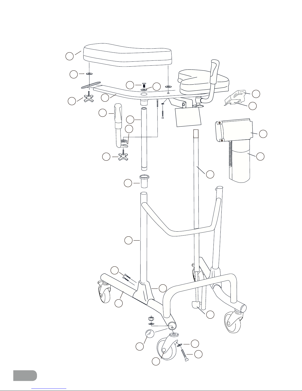
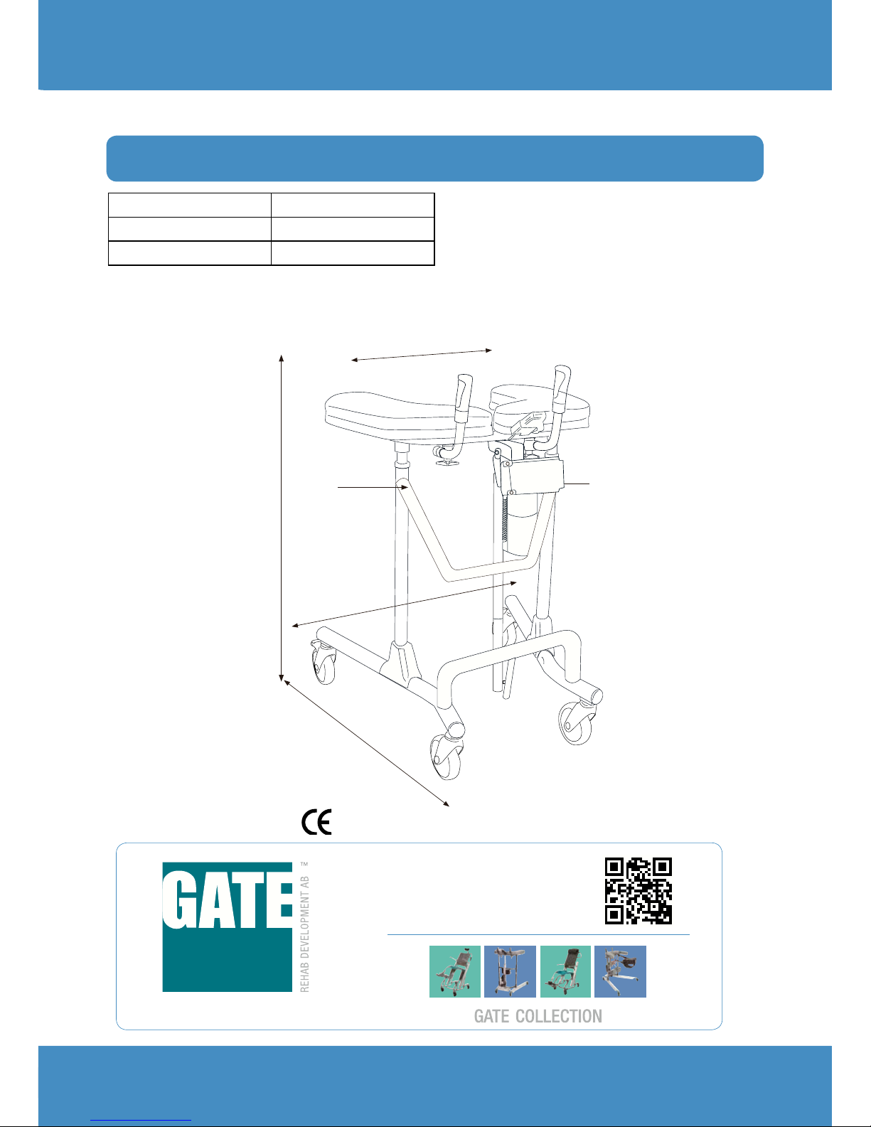
Gate Bure Ortho (S) Gas User manual

1
Bure
Walker
™
Technical Manual
digital
Bure Ortho 56-317T
Bure Ortho (S) Gas 56-318 (-S)
Bure Space 56-304
Bure Space Gas 56-307

2
2
1
3
STANDARD
4
10
9
8
7
56
11
12
13
14
15
16
17
18
19
23
25
24
22
21
20

3
1 Arm rest plate
2 Plastic washer
3 Knob
4 Upper frame
5Attachment bolt (2 pcs)
6 Serrated washer
7 Handle and grip
8Chromium-plated tube
9 Clamp
10 Knob
11 Guide sleeve
12 Intermediate frame
13 Bolts
14 Protective cover
15 Base frame
16 End bushing
17 Castor
18 Bolt
19 Washer
20 Cover/green
21 Actuator
(T-Motion)
22 Control box
(T-Motion)
23 Battery
24 Holder/ remote
control
25 Remote control
(T-Motion)
26 A Gas strut
B Handle
C Arm/housing
D Bolt, washer
(2 pcs), nut
(attachment at
bottom and top)
Parts list
Detaljförteckning • • •
1 a) Armstödsplatta b) ratt c) plastbricka
2 d) Handtag+grepp e) klämma f) ratt
3 Överstativ
4 g) Kromat rör h) Infästningsbult
(2 st) i) taggbricka j) ändbussning
5 k) Stativ l) styrhylsa
6 m) Skyddskåpa n) skruvar
7 o) Hjulstativ p) ändbussning q)hjul
r) bult s) bricka t) mutter u) taggbricka
3
9
10
a
b
c
d
a
d
ef
8 Låsvred för höjdjustering
9 a) Gaskolv b) handtag c) arm/hus
d) skruv + brickax2 + mutter
(infästning nedtill, upptill)
10 a) Batterihylla + fästskruvar
b) Batteri + skruv/mutter
(för fastsättning på batterihyllan)
c) ställdon + Styrbox
d) fjärrkontroll
e) skruv + brickax2 + mutter
(infästning nedtill, upptill)
b
c
26
GAS
A
B
C
D
Ortho/Space El 1-25
Ortho Gas 1-20, 26

4
No. Part No. Description
1 57-357-R Arm rest plate, right
1 56-357-L Arm rest plate, left
2 57-904 Plastic washer/Arm support widening
3 56-364 Knob for adj. width of arm rest plates
4 57-356 Upper frame
5 57-816 Attachment bolt, M10x40
6 57-803 Serrated washer
7, 9,10 56-353 Handle kit (2 pairs incl. attachment knob/clamps)
8 58-311 Guide tube with bronze bushings
10 56-363 Knob for adjusting handle
11 56-340 Guide sleeve
12 57-355 Intermediate frame,
13 57-810 Bolt M8x45
14 56-375 Protective cover, plastic
15 57-354 Lower frame Bure Ortho
15 57-354-S Lower frame Bure Ortho S
15 57-354-S Lower frame Bure Space
16 56-344 End piece, lower frame, Black/D45
17 56-361 Castor with brake 125mm
- 56-357 Castor without brake 100 mm
- 56-358 Castor with brake 100 mm
- 56-360 Castor without brake 125 mm
- 56-387 Castor with brake 75 mm
18 - Bolt M10x50
19 57-848 Nordloc washer
20 58-331 Cover/green (T-motion)
20 58-332 Cover/green (Linak)
21 58-377 T-Motion – Actuator (Raise/Lower)
22 58-373 T-Motion – Control box 220 V
22 58-373-1 T-motion- Control box 110 V
23 58-376 T-Motion – Battery
24 57-041-2 Holder, hand controller
25 58-374-1 T-Motion – Hand control (Raise/Lower)
- 56-305 Touch-up paint, Bure Silver 8
- 58-326 T-Motion – Power cable, coiled
- 58-326-1 Power cable, coiled UK
- 58-326-2 Power cable, coiled US
- 58-326-3 Power cable, coiled AUS
26A 57-007-1 Gas strut 400mm
26B 57-329 Plastic handle
26C 57-008-2 Lever/Alu
Spare parts

5
Accessories
Part No. Description
56-326-0 Handbrake kit/2 handles
56-326-1 Handbrake kit/One-handed brake
56-327 Frame elevation kit, 70 mm
56-393 Footplate, short, Bure Ortho/Space
56-383 Footplate, long, Bure Ortho/Space
56-392 Drip holder
56-335 Attachment for drip holder
56-336 Oxygen holder
56-337 Side support, adjustable
56-338 Drip rod complete with attachment
56-389 Soft basket with attachment
56-061 Remote control PLUS (TH10) including Holder
Remote Control Plus
**1. Service indicator – flashes red after 11 months’ operation.
Constant light (red) after 12 months’ operation. The indicator
is a reminder to review the maintenance instruction (see
Instructions for Use/Technical Manual. This should be done at
least once every 12 months.
Reset: hold down buttons <2a> + <2b>
for at least 30 seconds.
**The indicator will go out around 30 seconds after the remote control is
activated (battery conservation function).
2a 2b
1

6
1
2
3
4
Control box wiring
Remove the control box cover to make the connections as
described below. Use a screwdriver or similar; refer to
the special labels on the control box.
1. Socket for the raise/lower actuator.
NOTE! Make sure that plugs are connected to the correct
sockets otherwise the actuators can be damaged.
2. Remote control socket.
3. Battery terminal socket.
4. Plug socket. NOTE! The plug must ALWAYS be
connected to the control box for IP protection
to be valid.
Battery charging
Other instructions T-Motion
Connect plug to 230V wall socket. Charging begins automatically and the battery LED
flashes green.
Make sure the battery is fully charged before using for the first time. It takes around
25 h to fully charge the battery.
We recommend that the battery plug be removed from the control box if the product will be
out of use for an extended period (more than one week) or if the battery is switched off by
means of the ON/OFF switch. This eliminates the risk of disabling the battery as the control
box always uses a small quantity of electricity even when the walker is not in use.
• Control box – green light when power is available from battery/mains socket.
• Battery:
• The LED flashes green during charging.
• ON/OFF: To use the product, press ON.
• The green lamp will begin to flash.
• Use the OFF button (hold down for 5 s) to switch off the
battery if the product will not be used for an extended period.
• The LED will shows a constant green light when the battery
is fully charged.
• When the battery is in normal state/in operation, the LED
• flashes green at REGULAR intervals, namely 0.5 s ON, 4 s OFF.
• When the battery requires charging (remaining charge <25%) the LED will flash
• orange/red at REGULAR intervals, namely 0.5 s ON, 4 s OFF.
NOTE! The battery has an in-built device that automatically switches it off when
remaining charge is <20%. The LED is then extinguished. The battery must now be
fully charged before the electronics can be used again.
LEDs on control box and battery

7
5
3
4
1
6
2
56-317T
Walker Bure Ortho
78-78
Safety instructions
Warranty
ID label
Bure Walker may only be used;
• as a WALKING AID indoors
• on HARD, LEVEL surfaces.
MAX USER WEIGHT: 150 KG
We provide two years’ warranty for
manufacturing faults (does not apply
to wear parts). For further information
or enquiries please contact:
1. Part number
2. Product name
3. Date of manufacture
4. Max user weight
5. Serial number
6. EAN code
General maintenance advice
• Wipe the walker and its armrests clean as necessary;
use soap solution or alcohol-based surface disinfectant.
• The product may be cleaned in a tunnel washer or similar as electrical
systems have IP65 protection. However, the product is not corrosion
proof which means washing by machine may reduce its service life.
• Replace damaged parts immediately; must be done by experienced
personnel.
• The product is only intended for indoor use.
Gate Rehab Development AB
Industrigatan 2, SE-330 21 Reftele
Tel: +46 371 31800
info@gaterd.se
Recycling/Scrapping
When the product is no longer usable it should be recycled in accordance with legisla-
tion and regulations in the country concerned. All electrical parts including batteries
must be removed and recycled as electrical components. (Ask your local recycling
station for further information about how the different materials in the product (metals,
plastics, electronics) should be recycled).
1. Uttag för batterikontakt
2. Uttag för stickpropp
(OBS! För att IP-klassning ska gälla så ska
stickpropp ALLTID vara ansluten till styrbox)
3. Uttag för fjärrkontroll
4. Uttag för ställdon - höj/sänk
5. Uttag för ställdon - breddning (Endast
Bure Double)
OBS! Var noga med att kontakter ansluts
till rätt uttag eftersom detta annars kan
skada ställdon.
Kopplingsschema Styrbox Laddning Batteri
Laddning av batteri
Laddning av batteri ska ske då gåbordet inte
används. (Batteriet kan aldrig överladdas.)
Laddning görs genom att stickpropp ansluts
till eluttag.
Innan första användningen så
bör batteriet laddas 24 timmar..
2
3
4
1
5
Skötsel • • •
Generell skötselinstruktion Åtgärd
• Torka av gåbord och armstödsplattor vid behov – använd tvållösning
• Produkten ska ALLTID kännas stabil
Om gåbordet lutar eller har missljud – tillkalla servicepersonal.
• Byt ut trasiga delar omedelbart – skall göras av kunnig personal
• För gåbord med elställdon – använd ALDRIG gåbordet under laddning.
• Kontrollera att styrrör (g) är åtdragna i överstativ (3).
Övriga instruktioner • • •
5

8
Ortho, Space internal dimension = 250-500 mm
Ortho S 660 mm
Ortho 800 mm
7
Produktens vikt:.........Standard 13 kg / Gas 15 kg / El 21 kg
Max brukarvikt: .......... Standard 150 kg / Gas 150 kg / El 150 kg
”LYFT” anger lämpligt grepp vid lyft gåbordet vid transport.
OBS! Var minst två personer vid lyft.
LIFT LIFT
Ortho S, Space 790 mm
Ortho S internal dimension = 300-450 mm
Ortho, Space 785 mm
900-1300 mm
2016-10-04, 6
CE marked according to MDD 93/42/EEC
Ortho, S, Space
Product weight 20 kg (Gas 15kg)
Product height 900-1300 mm
”LIFT” denotes suitable handhold for lifting the walker.
NOTE! At least two people are required for lifting.
Dimensions
Would you like to know more?
Contact us at: Tel: +46 371 31800
Gate Rehab Development AB
Industrigatan 2 | SE-330 21 Reftele
WE DO BETTER.
This manual suits for next models
4
Table of contents
Other Gate Mobility Aid manuals

Gate
Gate Bure Standard User manual

Gate
Gate Bure Rise & Go User manual

Gate
Gate Bure Standard User manual

Gate
Gate Bure StandTall User manual

Gate
Gate Bure User manual

Gate
Gate BURE EXTRA User manual

Gate
Gate Basic 56-280 User manual

Gate
Gate Bure EXTRA 56-315 User manual

Gate
Gate Bure Walker User manual

Gate
Gate 56-315 User manual
Popular Mobility Aid manuals by other brands

Quickie
Quickie P-11 instruction manual

Vitea Care
Vitea Care WHEELER user manual

Drive DeVilbiss
Drive DeVilbiss R6RD-59 instruction manual

Drive DeVilbiss Healthcare
Drive DeVilbiss Healthcare TORRO ACERO Instructions for use

Granberg
Granberg Verti 830 instruction manual

Rebotec
Rebotec ECO 100 User instructions