Operations Manual
Page 3
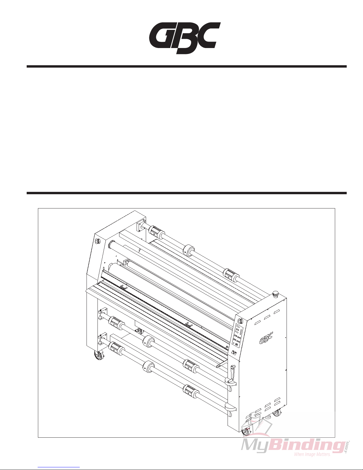
FALCON 60+ (-1) CE
©2004 General Binding Corporation
Table of content
Cover ............................................................... 1
Table of Content ............................................... 3
Important Safety Instructions ........................ 5
Important Safeguards ..................................... 7
General .............................................................. 7
Electrical ............................................................ 7
Service ............................................................... 7
Warranty ........................................................... 9
Specifications .................................................11
Pre-Installation ............................................... 13
Installation ...................................................... 15
Features Guide ............................................... 17
Power Switch ....................................................17
Control Panel Indicators ....................................17
Control Panel Buttons .......................................17
E-Stop ............................................................. 18
Safety Shield Interlock Latch ........................... 18
Safety Shield .................................................... 19
Feed Table ....................................................... 19
Chill Idler .......................................................... 19
Film Shaft ......................................................... 19
Main Rollers ..................................................... 19
Idler Bar ........................................................... 19
Pull Rollers ....................................................... 19
Rewind Tube .................................................... 19
Film Shaft Brake .............................................. 20
Core Adapters .................................................. 20
Center Core Support ........................................ 20
Rewind Brake ................................................... 20
Main Roller Crank Handle ................................ 20
Pull Roller Crank Handle .................................. 20
Cooling Fans .................................................... 20
Clutch ............................................................. 20
Accelerator Footswitch ..................................... 21
Rear Table Latches .......................................... 21
Rear Table ........................................................ 21
Rear Run/ Stop Switch ..................................... 21
Film Web .......................................................... 21
Nip Point ........................................................... 21
Rear Slitter ....................................................... 21
Separator Bar ................................................... 21
Operating Instructions .................................. 23
Film Loading and Threading ............................ 23
Webbing Thermal Film ..................................... 24
Webbing PSA Film ........................................... 25
Start Laminating ............................................... 26
Tacking New Film ............................................. 27
Unweb the Laminator ....................................... 28
Clearing a Film Jam ......................................... 28
Applications ................................................... 29
Mounting Pre-Coated Boards .......................... 29
Single Sided Lamination .................................. 29
Accushield ........................................................ 31
Custom Application #1 ..................................... 31
Custom Application #2 ..................................... 31
The Art Of Lamination ................................... 33
Basic Rules ...................................................... 33
Film Tension ..................................................... 33
Heat ............................................................. 34
Output ............................................................. 34
Maintenance ................................................... 35
Caring for the Falcon 60+ (-1) .......................... 35
Troubleshooting Guide ................................. 37
Service Agreement ........................................ 37


 User manual")