GE 750 User manual

Carestation™750
Anesthesia Delivery System
Clinical Reference Guide
Version 1.0
gehealthcare.com

ii

iii
Notice
Congurations available for this product depend on local market and standards requirements. Illustrations in this
course may not represent all congurations of the product. This guide does not cover the operation of every
accessory. Screens displayed in this training are examples only and may vary from your system due to software,
options, and database. Always refer to your application for exact screen representation.
The materials contained in this guide are intended for educational purposes only. This guide does not establish
specications, operating procedures, or maintenance methods for any of the products referenced. Always refer to
the ocial written materials (labeling) provided with the product for specications, operating procedures, and
maintenance requirements.
The materials contained in this guide are intended for educational purposes only. These materials may include
clinical concepts and denitions.
No diagnostic statements are inferred or included in these materials. All clinical diagnosis should be made by a
trained physician or clinician. All patient names or other protected health information or data contained in any image
within this material is ctitious. Any similarity to actual persons is coincidental.
Clinical Reference Guide
Version 1.0
Carestation™750
Anesthesia Delivery System

01 System overview ..............................1
Introduction . . . . . . . . . . . . . . . . . . . . . . . . . . . . . . . . . . . .1
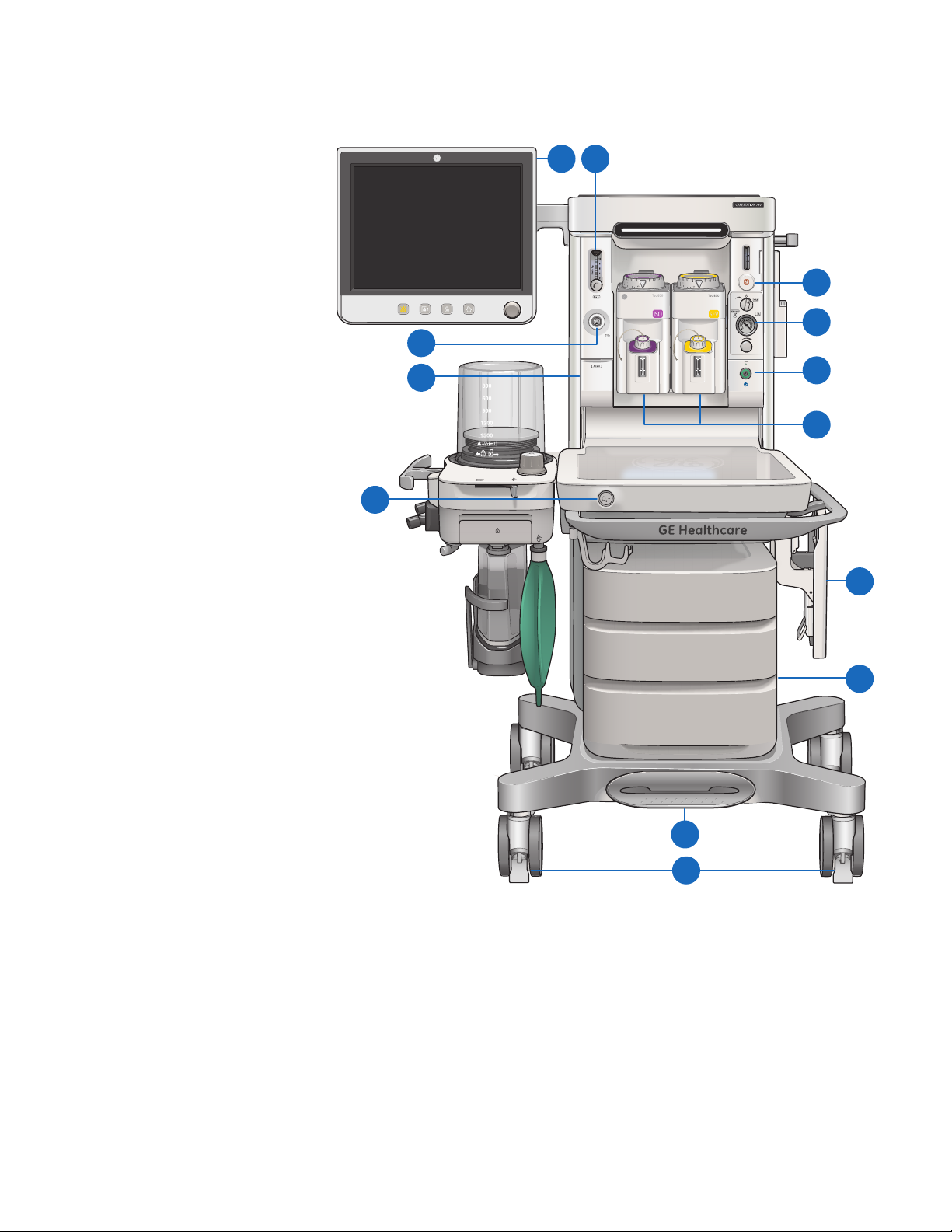
Front view components .........................2
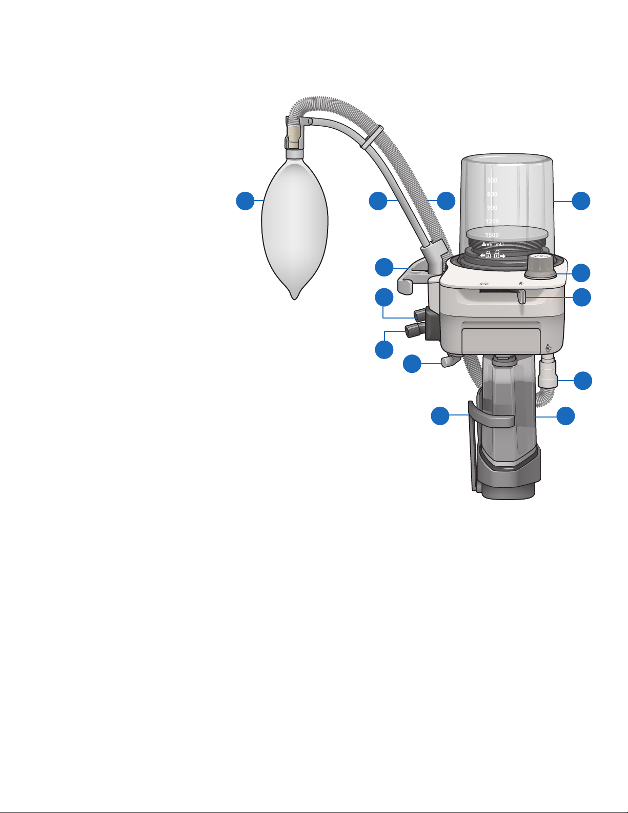
Breathing system components..................3
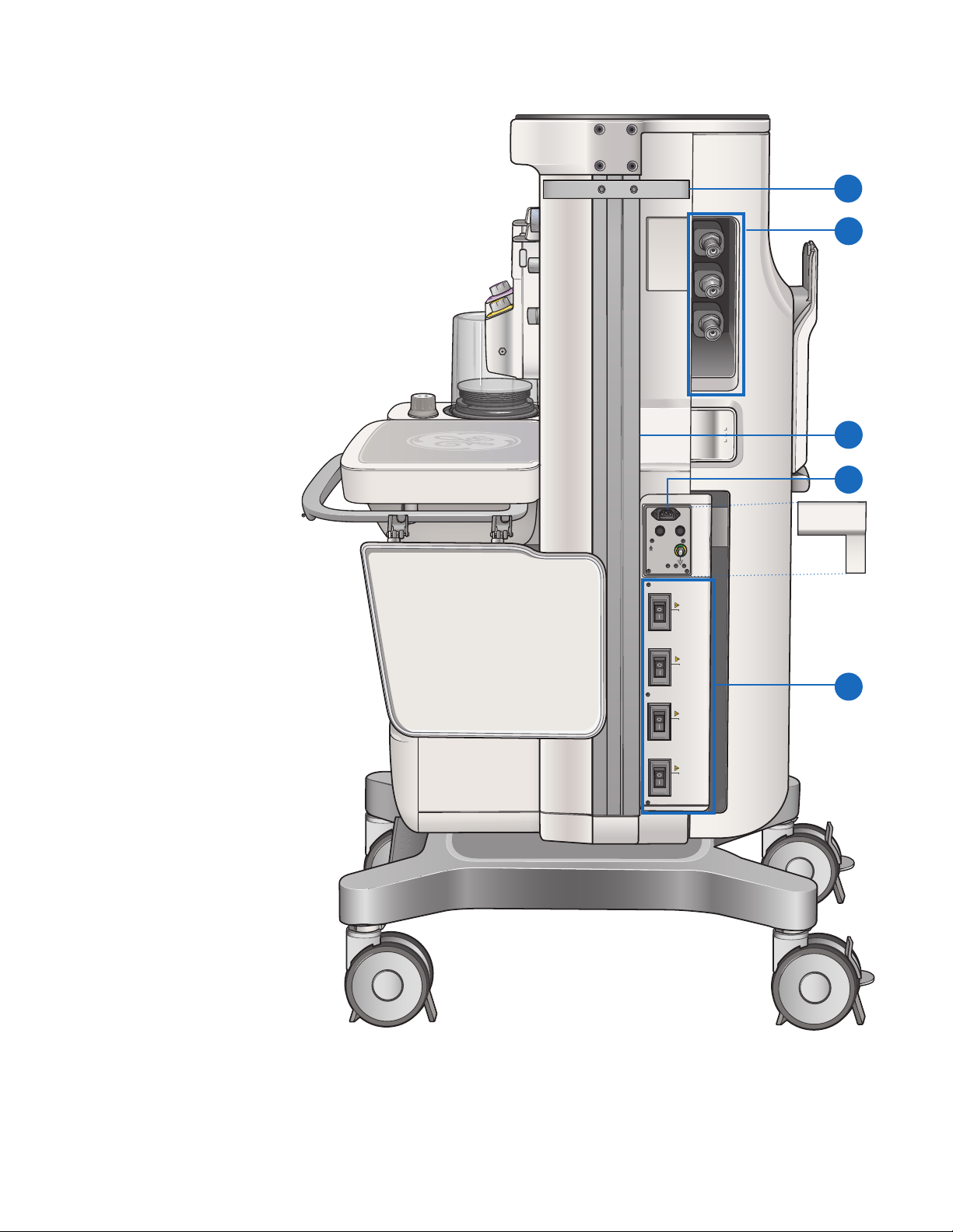
Right side view components . . . . . . . . . . . . . . . . . . . .4
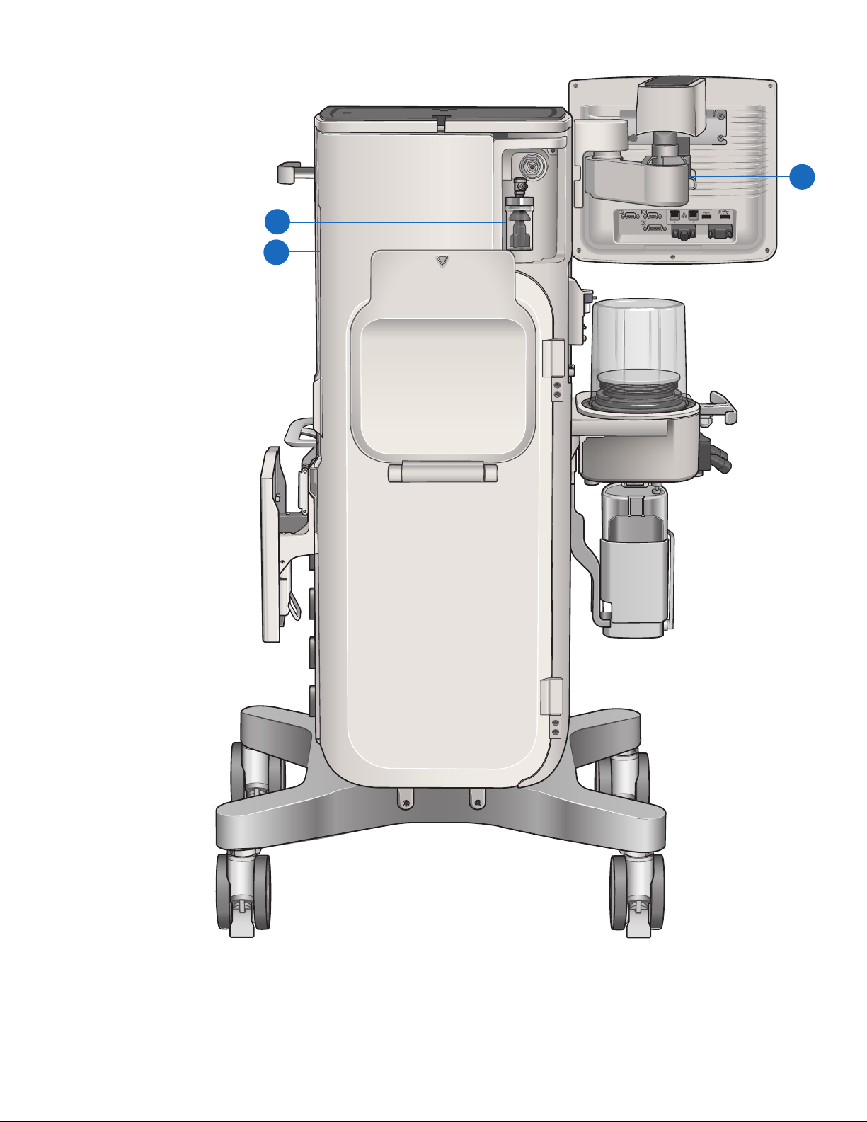
Rear view components..........................5
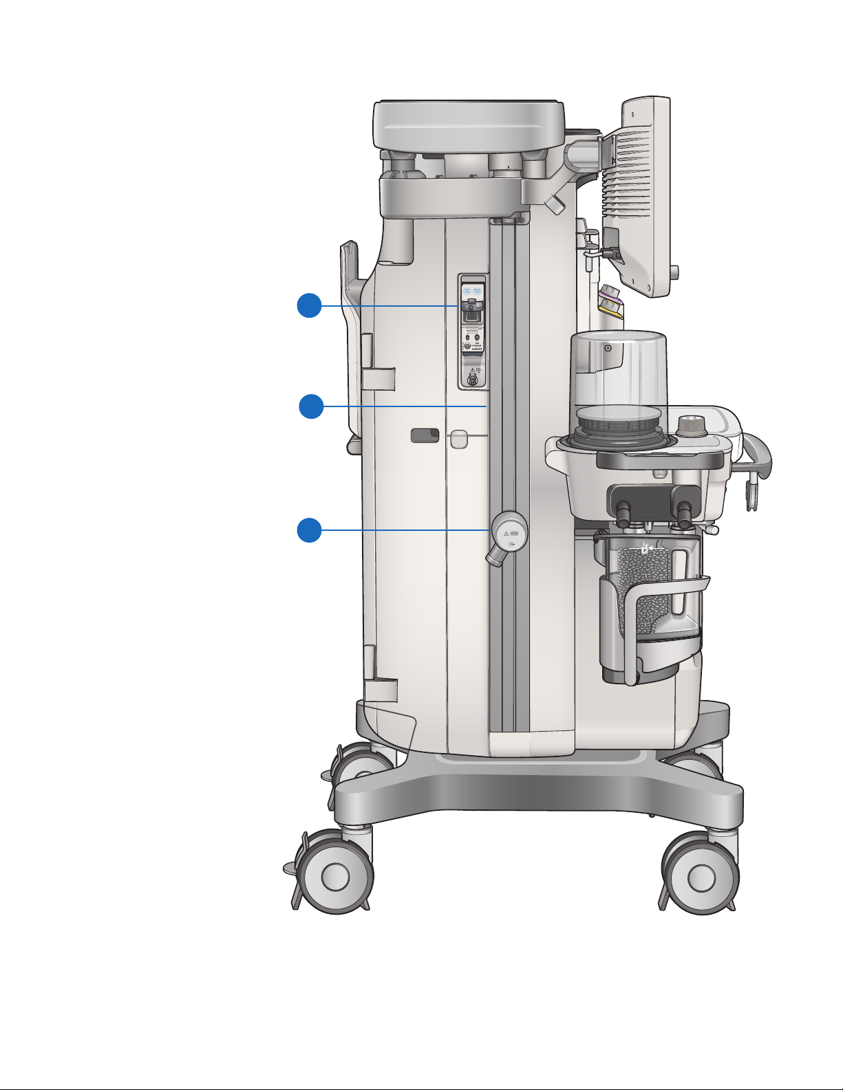
Left side view components......................6
Central and caster brakes .......................7
Using the bag support arm ......................8
02 Navigation . . . . . . . . . . . . . . . . . . . . . . . . . . . . . . . . . . . . 9
Display Controls . . . . . . . . . . . . . . . . . . . . . . . . . . . . . . . .9
Touch points ...................................10
Anesthesia system display .....................11
Using menus ...................................12
Using the ComWheel.......................... 13
Using quick keys . . . . . . . . . . . . . . . . . . . . . . . . . . . . . . .14
03 Operation overview ..........................15
Turning on the system . . . . . . . . . . . . . . . . . . . . . . . . .15
Changing gas settings..........................16
Using the O2 ush button ......................16
Using the APL valve . . . . . . . . . . . . . . . . . . . . . . . . . . . .17
Using the Bag/Vent switch . . . . . . . . . . . . . . . . . . . . .17
Using the vaporizer . . . . . . . . . . . . . . . . . . . . . . . . . . . .18
Using the ACGO................................18
Aux O2+Air .....................................19
04 Checkout.....................................20
Checkout overview............................ 20
Checkout full test ..............................21
05 Starting a case . . . . . . . . . . . . . . . . . . . . . . . . . . . . . . .22
Start Case menu overview . . . . . . . . . . . . . . . . . . . . .22
Starting a case using default settings...........23
Starting a case using custom settings ..........24
Starting manual ventilation . . . . . . . . . . . . . . . . . . . .25
Starting mechanical ventilation . . . . . . . . . . . . . . . .25
Changing a ventilator mode and settings .......26
06 Alarms and Trends............................27
Setting alarm limits . . . . . . . . . . . . . . . . . . . . . . . . . . . .27
Additional alarm settings ......................28
Setting Auto Limits . . . . . . . . . . . . . . . . . . . . . . . . . . . 29
Viewing Trends................................ 29
07 Ventilation modes . . . . . . . . . . . . . . . . . . . . . . . . . . . .30
Volume control mode (VCV)................... 30
Pressure control mode (PCV).................. 30
PCV-VG mode..................................31
SIMV VCV mode................................31
SIMV PCV mode................................32
SIMV PCV-VG mode ............................33
PSVPro™ Ventilation Mode .................... 34
CPAP + PSV mode............................. 34
08 Special features ..............................35
ecoFLOW overview . . . . . . . . . . . . . . . . . . . . . . . . . . . .35
ecoFLOW menu components ..................36
Activating the ecoFLOW split screen . . . . . . . . . . .37
Recruitment Maneuver.........................37
Pause Gas Flow ............................... 38
Spirometry overview...........................39
Spirometry loop components ................. 40
Saving, viewing and deleting spirometry loops 40
Spirometry setup ..............................41
Cardiac Bypass................................ 42
09 End of Case and Standby......................43
End Case.......................................43
Standby....................................... 44
Turning o the system . . . . . . . . . . . . . . . . . . . . . . . . .45
iv
Contents

1
01 System overview
Introduction
The Carestation 750/750c anesthesia systems combine advanced anesthesia delivery, patient monitoring, and care
information management. Optional integrated features include auxiliary common gas outlet, auxiliary O2 outlet,
auxiliary O2+Air outlet, suction control and respiratory gas monitoring.
Intended use
The Carestation750/750c anesthesia systems are
intended to provide monitored anesthesia care, general
inhalation anesthesia and/or ventilatory support to a
wide range of patients (neonatal, pediatric, and adult).
The anesthesia systems are suitable for use in a patient
environment, such as hospitals, surgical centers, or clinics.
The systems are intended to be operated by a clinician
qualied in the administration of general anesthesia.
Note: The Carestation 750 system is the standard
trolley system, while the Carestation 750c system is
the pendant system. This clinical reference guide will
focus on the standard trolley system and use the term
“Carestation 750” instead of “Carestation 750/750c”.
The operation of both systems is identical.

2
Front view components
1. Anesthesia display
2. Auxiliary O2 ow control (optional)
3. Alt O2 ow control
4. Suction regulator and control
(optional)
5. On/Standby switch
6. Vaporizer
7. Flip-up shelf (optional)
8. Drawers
9. Central brake
10. Caster brakes and cable sweeper
11. O2 ush
12. Auxiliary Common Gas Outlet
(ACGO) or Auxiliary O2+Air switch
and port (optional)
13. Auxiliary O2 outlet (optional)
3
1
4
2
5
6
7
8
10
9
11
12
13

3
Breathing system components
1. Bellows assembly
2. Adjustable pressure-limiting (APL) valve
3. Bag/Vent switch
4. Bag hose connection
5. Absorber canister
6. Absorber canister lifter handle
7. Leak test plug
8. Inspiratory port
9. Expiratory port
10. Breathing system guard
11. Bag hose
12. Bag support arm (optional)
13. Breathing bag
2
10
3
4
6
7
8
9
5
11213 11

220-240 V~
50/60 Hz
5 A
Class I
1 A
220-240 V~
1 A
220-240 V~
1 A
220-240 V~
1 A
220-240 V~
4
Right side view components
1. Side rail
2. Pipeline connections
3. Right dovetail
4. Mains inlet and Mains power fuses
5. Outlet circuit breakers (optional)
3
1
2
5
4

5
Rear view components
1. Display arm
2. Suction trap
3. Back cover (optional)
RS 232
2
3
1
2

6
Left side view components
1. Airway module (optional) and
sample gas return port
2. Left dovetail
3. Anesthesia Gas Scavenging System
(AGSS) connection
Save
Loop
Change
Loop
Spirometry
M
3
1
2

7
2
Central and caster brakes
The Carestation 750 system has one
central brake with two brakes on
the rear casters that hold the system
in place.
1. Central brake: Push down on the
central brake to lock the system
in place. Lift up on the central
brake to release the brake.
2. Caster brakes: Push down on
the lower portion of the brake
pedal to lock the system in place.
Push down on the upper portion
of the brake to release the brake.
Locked position
Unlocked position
1

Using the bag support arm
Use the optional bag support arm to hold
the breathing circuit bag.
The bag support arm can be moved up or
down and left or right.
8
Bag support arm

9
02 Navigation
Display Controls
1. Touchscreen: Activates functions when touch areas on the screen are selected.
2. Audio Pause key: Stops audio for 120 seconds for any active, eligible high and medium priority alarms. Prevents
audio (audio o) for 90 seconds when no medium or high priority alarms are active.
3. Start/End Case key: Initiates Start or End Case function.
4. Screen Lock/Unlock key: Locks the touchscreen. Toggles between lock and unlock functions.
5. Home key: Removes all menus from the screen.
6. ComWheel: Selects a menu item or conrms a setting. Turn clockwise or counterclockwise to scroll through
menu items or change settings.
4 52
1
3 6

10
1. Wave elds
2. Measured values
3. Function keys
4. Digit elds
5. Ventilator quick keys
6. Gas quick keys
7. Split screen values
Touch points
7
12
4
56
3

11
1 2 3 4 65
Anesthesia system display
1. Audio pause symbol and countdown clock: Indicates when alarm audio is paused and the countdown clock
until audio is on.
2. Alarmmessageelds: Displays the active alarms.
3. Waveformelds: Displays the waveforms of measured values.
4. Generalmessageeldsorlocktouchscreenindicator: Displays general messages and the touchscreen
lock indicator.
5. Measuredvalueselds: Displays the measured values.
6. Clock: Displays the current time.
7. Function keys: Select functions such as Audio Pause, Trends, etc.
8. Digitelds: Contains information for Spirometry, Resp, Agent, and Gases.
9. Ventilator quick keys: Displays Mode, associated ventilation parameters, and More Settings. The selected
ventilation mode will be displayed directly above the quick keys.
10. Gas quick keys: Displays O2, Total Flow, and Gas Setup.
11. Split screen: Contains airway pressure, gas ow values, compliance, trends, and optional ecoFLOW information.
8
910
11
7

12
Using menus
1. Menu: Displays the title of the open menu. For
example: Start Case.
2. Menu items: The menu items will vary depending
on the selected menu.
3. Instructions or help information: This shows any
additional instructions or help messages.
1
2
3

Turn the ComWheel to the right:
• For menu items, the highlight moves down
• For quick keys, the highlight moves to the next key on the right
• For settings, the value changes to the next available setting
• For pull-down selections, the highlight moves to the next available selection
• Push the ComWheel to conrm a setting
Turn the ComWheel to the left:
• For menu items, the highlight moves up
• For quick keys, the highlight moves to the next key on the left
• For settings, the value changes to the previous available setting
• For pull-down selections, the highlight moves to the previous available selection
• Push the ComWheel to conrm a setting
13
Using the ComWheel
Use the ComWheel to scroll through the quick key settings and function keys, make selections, change settings, and
conrm settings.

14
Using quick keys
The gas settings and the main
ventilator settings for each
ventilation mode can be changed
using the quick keys.
1. Select a quick key to open the
menu or select a parameter.
2. If O2, Total Flow, Gas Setup,
Mode or More Settings is
selected, a menu displays.
Select the desired value on the
menu by touching the value.
If any other quick key is selected,
the value displays with a
highlight. Turn the ComWheel
left or right to set the desired
value.
3. Push the ComWheel or select
the quick key to conrm the
change.
12 3

15
03 Operation overview
Turning on the system
Plug the power cord into an
electrical outlet.
1. Make sure the mains indicator
light is on.
• The mains indicator is lit
when AC power is
connected
• Battery is charging if it is
not already fully charged
2. Push the On/Standby switch for
1 second to turn on the system.
1
2

16
Changing gas settings
1. Select the Gas Setup quick key.
2. For Other Gas, select the menu
item and change using the
drop-down menu.
3. For O2%, and Total Flow, select
the setting and make the change
using the ComWheel and push to
conrm the setting.
The O2 ush button supplies a high
ow of O2 to the breathing system.
1. Push the O2ush button to deliver
a high ow of O2.
2. Release the O2 ush button to stop
the delivery of a high ow of O2.
Gas Setup
Other Gas
Set O2 concentration in fresh gas..
Total Flow
l/min
Air
Close
O2%
%
6.00
100
2
3
1
Using the O2 ush button
Other manuals for 750
5
This manual suits for next models
1
Table of contents
Other GE Medical Equipment manuals