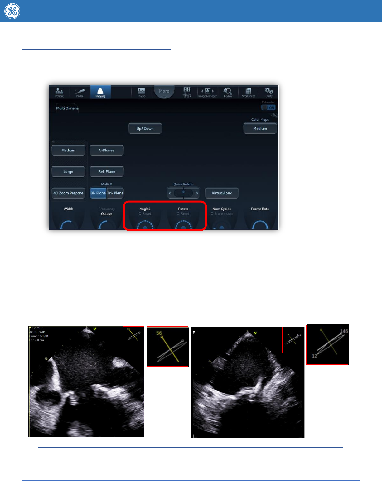
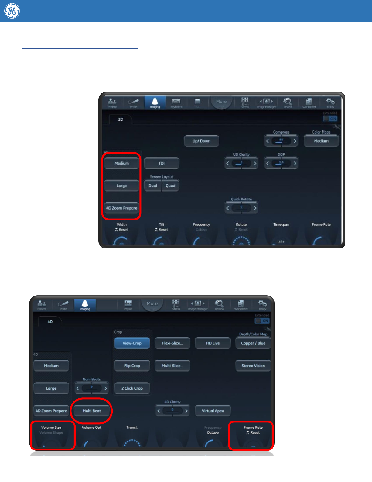
manuals.online logo
Brands
  1. Home
  2. •
  3. Brands
  4. •
  5. GE
  6. •
  7. Medical Equipment
  8. •
  9. GE Vivid E95 Assembly instructions

GE Vivid E95 Assembly instructions

4D TOE
Tips & Tricks
Kylie Hollitt
CVUS Applications Specialist GE healthcare
Australia
2 JB83797AU
Welcome to your 4D probe
Pages
Title
Description
3
Setting Up
System configuration
4
Getting to know you
6VT TOE probe configuration
5-6
Angle + Multi D
Biplane –Rotating and Tilting,
7-8
Angle + Multi D
Biplane - V Planes, Triplane
9-10
Acquiring 4D Workflows
Acquiring Larger 4D volumes
11-13
Acquiring 4D Workflows
4D Flexi Zoom
14
Acquiring 4D Workflows
FlexiViews
15
4D Tools –Live and Post
Processing
2 Click Crop
16-18
4D Tools –Live and Post
Processing
Flexi- Slice
19
4D Colour
Obtaining 4D Colour images, Optimisation Tips
20
4D Optimisation Controls
Knobology
Appendix
Quantification Tools
For more tips, webinars and resources visit the Vivid Echo Club
www.vividechoclub.net
3 JB83797AU
Setting Up/ Before You Start
Plug your TOE probe into the system and Press the “PROBE” icon on the touchscreen to activate your
6vt TOE probe. The available presets will be listed under this probe –the machine will automatically
default to the probe at the top of the list.
You will see the 6vt Probe steering angle appear on the screen confirming that a TOE probe has been
activated.
If your system is setup to provide a preview loop prior to store –your cardiologist may wish for this
feature to be turned off for the Transosephageal Echocardiogram.
To access this you will want to go to the Utility button on your touchscreen (if it’s not a shortcut press
on “MORE”) and into the Configuration menu –The Global/ Imaging screen should come up
automatically - if not go to the Global/Imaging tab to view the following screen and turn of preview
prior to store –Note you must turn this back on again after if it is required for transthoracic scanning
4 JB83797AU
Getting to know your TOE probe
TOE probe default set up
1. Button 1 (closest to the probe tip):
Counterclockwise scan plane rotation or rotate right
(takes the angle) from zero degrees forward)
2. Button 2: Image Store
3. Button 3: Clockwise scan plane rotation or rotate
left (takes the angle back towards zero degrees)
To customize these settings go to the Utility button
on your touchscreen. Press Config go to the
Imaging tab and press the TEE probe subtab
Cleaning the TOE probe
The TOE probe should be
processed immediately –do not
allow body fluids to dry on the
probe.
Products that are approved for use
on GE TOE probes are listed on the
following website link. Using non
approved products may void your probe warranty.
http://www3.gehealthcare.com/en/Products/Categories/Ultrasound/Ultrasound_Probes
Approved products should be used according to manufacturers guidelines however cleaning agents
must not come into contact with the probe system connector plate (7).If you have any other questions
regarding cleaning agents or the cleaning procedure contact your GE representative or refer to the TEE
User Manual for technical guidance.
5 JB83797AU
Single Plane imaging - Angle and Rotate
The Angle button is available on both the console and the touchscreen (Quick
Rotate). Pressing either will steer the angle of the probe internally at 30 degree
intervals. Pressing “Clear” on the console will take the angle straight back to zero.
Use the “Rotate” rotary knob to change the angle of the scan
plane 1 degree at a time.
Multi D –Biplane mode
•Select the “Multi D” button, a Biplane image will appear.
•Scan Plane (1) is the image in relation to the position and
orientation of the TOE probe –this image is highlighted by ayellow box –Thecurrent
angle of Scan Plane 1 is represented by ayellow line onthe onscreen navigator (3). Adjustments to the “Rotate”
knob will adjust the angle of this view.
•Scan Plane (2) defaults at an angle that is 90 degrees to Scan Plane 1. This image can be independently
tilted and rotated. If selected this image is bordered by a white box. Scan Plane 2’s angle is displayed as a white
line on the navigator (3) and may be adjusted independently using the “Angle 1” rotary knob.
1. Scan Plane 1 (yellow reference line) default scan plane
2. Scan Plane 2 (white reference line)
3. Navigator displays the position of both scan plane as seen from the probe.
4. Trackball functions.
6 JB83797AU
Rotating and Tilting –Biplane Mode
•The “Rotate” knob rotates all images together.
•Scan Plane 1 and 2 can be rotated independent of each other and Scan Plane 2 can also be tilted.
•The “Angle 1” rotary knob adjust’s the angle increment of Scan Plane 2.
•To tilt Scan Plane 2 press the “Select” mouse key until “Pos” is highlighted – Use the trackball to tilt the
second scan plane. Pressing the “Clear” button resets Scan Plane 2 back to a non-tilted position. Note: Tilt
and rotate can only occur in biplane mode.
Note example below : Scan Plane 1 is at 56 degrees (yellow) and Scan Plane 2 has defaulted to 146 degrees
(white) the operator has tilted the second scan plane to 12 degrees to better view a catheter as it is placed
through a perivalvular leak. To rotate Scan Plane 2 further use the “Angle 1” toggle. Moving Scan Plane 1 is
achieved by utilizing the "Rotate” toggle.
Clinical Suggestion –Utilise Biplane with tilt and rotate in Interventional settings to visualize the
Intra-atrial septum in two views during atrial septal puncture or to guide catheter placement.
7 JB83797AU
Multi–D - Biplane Mode
V Planes
Image a situation where you might normally need
to move the TOE probe to get a particular view I.e.
moving Trans-gastric to get a short axis. V-Planes
tilt the scan plane down reducing the need to
move the probe.
To begin enter Bi-Plane.
Select V -Planes and the scan plane 2 will
automatically rotate so that it is the same angle as
scan plane 1.
Ensure that Pos is highlighted as the current
trackball function.
Scan plane 2 can now be
tilted using the trackball
(up and down). To reset
the V- Planes press the
Clear button on the
console.
Note the navigator angle
on this image - both scan plane angles have defaulted to zero however scan plane 2 has been
tilted up 20 degrees using the trackball function.
8 JB83797AU
Multi D - Triplane Features
•Change to Triplane on the touch screen (default is to Biplane)
•Move probe as needed so that you can clearly see all three views.
•In Tri-Plane the third scan plane (A2 or Angle 2) is represented by a green line - to change the angle of
the third image press the “Angle 1” rotary knob so that “Angle 2” is highlighted – turning this knob will
rotate the third image individually.
Want to learn more, go to www.vividechoclub.net for online tutorials, webinars and product information.
9 JB83797AU
Obtaining larger 4D volumes
Enter your 4D image by either pushing 4D on the console or pressing Medium or Large on the touch
screen (selection dependant on volume size required). You may like to consider a reduction in
Frequency to assist with improving the Penetration for your larger volume.
To acquire a 4D
dataset of the
valves, left atrial
appendage or IAS
consider using
Flexi Views or 4D
Flexi Zoom (see
relevant sections
below for more
information).
Once you are in your 4d screen you can make further adjustments to the size using the Volume
size/shape toggle.
Frame Rate and
Multi Beat options
are also available
on this touch
screen. Note
adjustments to
Frame Rate will
affect the spatial
resolution.
10 JB83797AU
4D Zoom
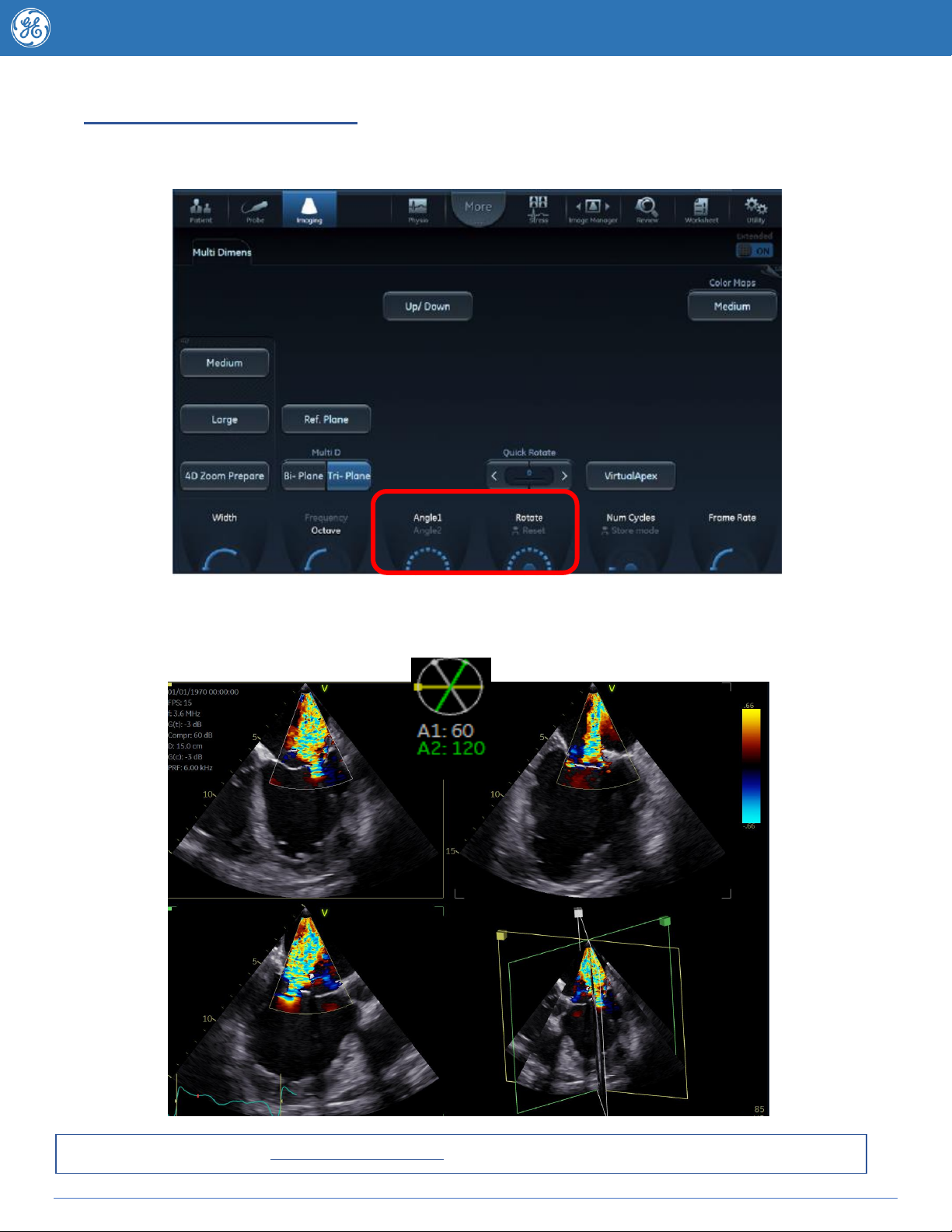
Hit 4D Zoom Prepare on the touchscreen and you will be taken to a biplane image as per below
Adjusting Zoom region of interest -The
trackball will default to Position adjustment inthe
Azimuth plane (The left box). Pressing the
trackball Set key changes the ROI box between
the position and region size adjustment.
Optimise until satisfied.
To adjust the view in the elevation plane (Image
to the right) press your Trackball button or Ref
plane on your touchscreen. As per the Azimuth
plane use the trackball Set button to switch
between position and size adjustment.
When you are ready to view
your 4D image press the 4D Button on the console (note pressing 4D Zoom turns
off the 4D zoom feature) to be taken to the 4D rendered image. The default 4D
rendered image displayed will be dependant on the saved default position of your
Translate line. Move the Translate line position by adjusting the rotary knob or
adjust the angle of this line using the Angle button on your console. To alter the
displayed Layout press the Layout button on your console.
Now that you have your 4D dataset refer to the optimization section of this tips book to see which post
processing features can assist you further.
11 JB83797AU
4D Zoom with Flexi Zoom –Fast, flexible visualization of the heart structures
The 4D zoom buttons provide quick live access to main heart structures, with no need for further volume
cropping or rotation.
To begin –obtain the ASE/SCA standard view & enter via the 4D Zoom Prepare button and follow the
steps in the 4D zoom section.
When you are happy with your ROI instead of pressing 4D press any of the quick access buttons as
highlighted by the red box above. Examples for each button follow below.
Acquiring 4D Surgeons View of the Mitral Valve –Using 4D Flexi Zoom
When you have optimized your ROI boxes press the Mitral Valve button on the touchscreen and you
will be taken through to the surgeons view of the mitral valve.
The Rotate Z knob
can be used the
adjust the angle of
the 4D dataset if
it’s a couple of
degrees off.
12 JB83797AU
Using the 4D zoom TOP DOWN button
4D zoom Top Down is helpful for any structure you wish to see from the Top –down, this makes it
especially helpful for 4D left atrial appendage and interatrial septum acquisition.
When you are ready to view your 4D image press the Top Down button on the
touchscreen and you will be taken through to the 4D rendered view.
The Rotate Z knob can be used the
adjust the angle of the 4D dataset if it’s
a couple of degrees off (represented by
yellow arrow).
The “Yellow” arrow on the 2D reference
planes represents the viewing
direction.
The brown Translate line (visible on
the 2D images) can be moved using
the translate knob at the bottom of the
touchscreen –to optimize the image
move it closer to the region of interest
–you can also use 2 Click Crop to
crop the image down in a parallel fashion.
Remember a darker 2d image may produce a nicer 4D image –if it’s difficult to see the structures due
to blurring try turning down the large 2D gain knob.
Adjust Zoom region of interest -
The trackball will default to Position
adjustment in the Left box (it is
highlighted in yellow). Pressing the
selectkey changesbetween position
and region of interest size
adjustment. Optimise until satisfied.
To adjust the view in the right box
(Image to the right in above picture)
press your trackball button or touch
Ref Plane on your touchscreen. As
per the Azimuth plane use the Set
button to switch between position
and size adjustment.
13 JB83797AU
Acquiring 4D Aortic valve using Enface Left/ Right
The Enface Left/Right Flexi Zoom buttons allow you to quickly view the image displayed in either the
left or right 4D zoom plane in 4D –to access press either Enface Left or Right onceyou have optimized
your ROI boxes.
Note if you acquire a long axis you can change to a short axis live or post acquisition by using the Angle button.
Adding more definition to that AV 4D dataset
The first thing to consider with your aortic valve dataset is your gains.
A darker 2D Gain will produce a clearer 4D dataset.
When in 4D your Active Gain knob becomes 4D gain.
To add more 4D definition to your structure turn the Active Gain knob down a notch or two.
It may also be necessary to adjust the Translate line to optimally display 4D structures.
14 JB83797AU
Flexi Views –4D acquisitions made easy
Provides one touch access to factory defined views or user created views for faster, easier workflow.
To select or create new Flexi Views press the subtab on the touchscreen.
Available views are specific for each probe preset –press Configure on your Flexi Views touchscreen
to be taken directly to the configuration screen seen below.
Want to learn more, go to www.vividechoclub.net for online tutorials, webinars and product information.
Clinical Suggestion –Create/save new Flexi Views mid procedure to enable fast, one
touch return to optimized views.
15 JB83797AU
2 Click Crop
2 Click Crop allows the user to create a parallel crop on any structure. 2 Click crop can be entered into
live or post image acquisition. To enter press 2Click Crop on the touch screen.
To use simply place the cursor where you wish to begin and start by clicking the mouse key and scroll
the trackball to begin your crop
Until a second point is finalized the angle of the cropping direction can be moved by moving the
trackball. Your selected crop will appear as the rendered 4D image to the right. To crop further simply
begin again on the desired image. To exit select 2 Click Crop again on the touch screen.
If you wish to change the viewing direction simply press flip crop on the touch screen. The translate line
may also be moved post crop to further adjust the viewing position.
Want to learn more, go to www.vividechoclub.net for online tutorials, webinars and product information.
16 JB83797AU
Flexi-Slice
Flexi-Slice is used to extract 2D cut planes from the 4D dataset. To start Flexi-Slice –press the Flexi-Slice
button on the touch screen while in 4D or 4D colour.
You will be taken to an image similar to below displaying both 2D slices and a rendered 4D image. The
layout displayed can be altered by using the Layout button. Alternatively you can press the desired layout
from the list on the touch screen.
Layout Features
Default –as seen above displays the 4D image with three 2d planes –the plane that is highlighted will
appear as the rendered 4D image. In the view above the “Green Cut Plane” is highlighted displaying a short
axis of the Yellow (Azimuth) and White (Elevation) cut planes as the 4D rendered view.
Biplanar –Displays the Yellow (Azimuth) plane and White (Elevation) plane as well as the rendered 4D
image
LAX –Displays the White and Yellow cutplanes in large view with short axis orientation lines for adjustment.
The two selected corresponding short axis cut planes are displayed to the bottom left.
SAX –Displays the two short axis planes in a larger view as per the orientation of the two long axis planes
which are displayed to the bottom left.
Single –Displays the single highlighted/ selected 2d plane
Clinical Suggestion –As seen above, Flexislice may be used to improve the accuracy of oblique 2D
measurements.
17 JB83797AU
Flexi-Slice tools
Lock Slices Allows you to rotate the slices whilst maintain a 90 degree angle between them
Rotate 4d Rotates the 4D image and the active slice while other slices remain unchanged
Rotate All Rotates the 4D image, the active slice and the lines.
In Flexi-Slice mode each cut-plane may be rotated or translated using the Trackball.
Press Yellow, White or Green on the Touch panel to select which 2d slice will be the Reference
plane for the 4D image. The volume rendering is updated accordingly. The example below shows
the Green Cutplane highlighted as the reference plane.
18 JB83797AU
To Make Adjustments in Flexi-Slice
1) Place the cursor at one of the extremities of a cut-plane intersection line in one of the cut-
planes. The cursor will change to a . Drag to rotate the cut-plane.
2) Place the cursor in the middle section of a cut-plane intersection line. The cursor is changed to
a . Drag to translate the cut-plane.
3) Place the cursor at the intersection between two cut-plane lines the cursor is changed to .
Both cut-planes are translated simultaneously.
4) Click on a point in the volume rendering to move the intersection of the two other cut-planes to
that location.
•If Depth Mode is turned on: the reference plane is also moved inside the volume
rendering to the corresponding selected depth.
•In Depth Mode is turned off: the reference plane is kept at the current depth.
5) Place the cursor at the outer area of one of the cut-planes. The cursor is changed to . Drag
to rotate the cut-plane image. The cut-plane lines remain fixed.
6) Place the cursor in the inner area of one of the cut-planes. The cursor is changed to . Drag
to pan the cut-plane image. The cut-plane lines remain fixed.
Want to learn more, go to www.vividechoclub.net for online tutorials, webinars and product information.
Rotate
Image
Drag to
translate
Cut Plane
Rotate
Cut
Plane
19 JB83797AU
4D Colour
To achieve a well optimised 4D colour image it is helpful to first optimise the Colour box size and
position in 2D mode. Biplane mode may further assist with optimal size and positioning. Enter into 4D
using either the 4D or 4D Zoom Prepare button. If you wish to adjust your Colour gain while in 4D ensure
the 4D CF tab is currently active on the touchscreen and then adjust the Active Gain knob.
1. 4D Volume rendering display with Colour Flow
2. 2D Colour Flow image in the azimuth plane –the yellow arrow indicates the view direction onto the volume relative to the
azimuth plane.
3. 2D Colour Flow image in the elevation plane –the yellow arrow indicates the viewing direction relative to the elevation plane.
4. Orientation window : displays 3D scene with acquisition sector and 2D image positions. 5. Translate line.
To optimize your viewing of regurgitant jets use the “Translate” knob to move the viewing plane line
down to the level of the vena contracta –this will display the regurgitant jet at its best.
1
2
3
5
4
Reduces Noise in
4D Colour –save
preset defaulted
on.
Frame rate is
equally important
for 4D colour.
Ensure the size of
the viewing plane
and the colour
box are
optimized. You
may need to use a
multibeat
acquisition if
frame rates are
not sufficient.
20 JB83797AU
4D tools
4D Feature
What it does
When to use and how
Frequency
of
adjustment
4D Gain
Affects the transparency of the volume
rendering.
Too much 4D Gain applied will take away
structures, too little will leave opaque “Gray
clouds” in the ventricle
As Necessary
4D Clarity
Edge preserving speckle and noise reduction
filter that reduces speckle while preserving or
even enhancing significant boundaries in the
volume data.
Increasing 4D Clarity will create images with
less visible speckle noise and with a softer
appearance.
AN
Angle
Sets the cut-planes and crop planes to pre-
defined positions.
Use to display different rendering views –
can be used in 2d mode to angle through
different views without rotating the probe
AN
Auto
Automatically optimizes the brightness of the 4D
image.
Use for quick optimization of image
brightness –further manual adjustments
may be required to suit individual
preferences.
AN
Clear
Sets the cut-planes and crop planes to the
default position.
Use to return to zero
AN
DDP
Performs temporal processing which reduces
random noise without affecting the motion of
significant tissue structures.
Reduce if there is too much smoothness in
the image.
Rarely (once
set to
desired level)
Frame rate
Adjusts the frames per second of the system –
adjusting means a trade of between spatial and
temporal resolution.
Use to avoid multibeat to get FR >13 for
LVQ –trade off with image resolution.
AN with
caution
Gamma
Adjusts the brightness of midtone values.
A higher gamma value produces an overall
darker image, a lower gamma value a
brighter image.
AN
HD live
Simulates light propagation and scattering
through tissue
Use for rendered images with realistic
looking soft shadows.
AN user
preference
Low velocity
reject (in 4D
Colour mode)
Removes low velocity blood flow and tissue
movement that reduces image quality.
Turn on during 4d colour acquisition to
improve
Rarely (leave
set to on)
Shading
Adjusts the shading effect on the volume
rendering
Use to improve three dimensional
perception.
Rarely
Smoothness
Affects continuity of structures and image noise
in the volume rendering.
Too much smoothness will blur the image,
too little will leave too much noise.
Rarely once
set
Translate
Translates the crop plane into the volume.
Adjust to move closer to structure of
interest and improve appearance of 4D
image.
Frequently
Colour
Transparency
(4D colour)
Adjusts the display transparency of color data.
An increase of Color Transparency may help
bring out relevant color flow information
(e.g. jet).
AN
Tissue
Transparency
(4D, 4D colour)
Adjusts the display transparency of tissue data.
An increase of Tissue Transparency may
help bring out tissue structures or flow
information behind obscuring tissue
structures.
AN

Other GE Medical Equipment manuals

GE MAC 1200 User manual

GE

GE MAC 1200 User manual

GE OPTIMA MR360 Manual

GE

GE OPTIMA MR360 Manual

GE Innova IGS 6 User manual

GE

GE Innova IGS 6 User manual

GE Healthcare Portascan User manual

GE

GE Healthcare Portascan User manual

GE Corometrics 170 Series User manual

GE

GE Corometrics 170 Series User manual

GE SIGNA Voyager User manual

GE

GE SIGNA Voyager User manual

GE IV-908 User manual

GE

GE IV-908 User manual

GE LOGIQ P3 PRO User manual

GE

GE LOGIQ P3 PRO User manual

GE Logiq 500 User manual

GE

GE Logiq 500 User manual

GE LOGIQ e User manual

GE

GE LOGIQ e User manual

GE LOGIQworks User manual

GE

GE LOGIQworks User manual

GE 750 User manual

GE

GE 750 User manual

GE MAC 1600 User manual

GE

GE MAC 1600 User manual

GE Compax 40E User manual

GE

GE Compax 40E User manual

GE PhastSystem User manual

GE

GE PhastSystem User manual

GE Vivid P3 User manual

GE

GE Vivid P3 User manual

GE Vivid 7 User manual

GE

GE Vivid 7 User manual

GE Responder 1000 User guide

GE

GE Responder 1000 User guide

GE LOGIQ E9 User manual

GE

GE LOGIQ E9 User manual

GE MAC 2000 User manual

GE

GE MAC 2000 User manual

GE Fluorostar User manual

GE

GE Fluorostar User manual

GE Responder AED Operation manual

GE

GE Responder AED Operation manual

GE LOGIQ 400 User manual

GE

GE LOGIQ 400 User manual

GE Optima XR646 User manual

GE

GE Optima XR646 User manual

Popular Medical Equipment manuals by other brands

Dräger Photo-Therapy 4000 Instructions for use

Dräger

Dräger Photo-Therapy 4000 Instructions for use

HealthCo Forte user manual

HealthCo

HealthCo Forte user manual

Labomed PRIMA ENT user manual

Labomed

Labomed PRIMA ENT user manual

InterX 1000 Getting started

InterX

InterX 1000 Getting started

Invacare 1085140 Assembly, installation and operating instructions

Invacare

Invacare 1085140 Assembly, installation and operating instructions

WARDRAY PREMISE GT5501P Operator's manual

WARDRAY PREMISE

WARDRAY PREMISE GT5501P Operator's manual

Otto Bock Genium Protector 4X880 Series Instructions for use

Otto Bock

Otto Bock Genium Protector 4X880 Series Instructions for use

Bosch PFP5230 operating instructions

Bosch

Bosch PFP5230 operating instructions

Lowenstein Medical SOMNOvent auto-S Instructions for use

Lowenstein Medical

Lowenstein Medical SOMNOvent auto-S Instructions for use

Labomed eVA 500 user manual

Labomed

Labomed eVA 500 user manual

Chattanooga 3D ActiveTrac user manual

Chattanooga

Chattanooga 3D ActiveTrac user manual

Fukuda Denshi DynaScope 7000 Series Operation manual

Fukuda Denshi

Fukuda Denshi DynaScope 7000 Series Operation manual

THERALASE TLC-2000 Series quick start guide

THERALASE

THERALASE TLC-2000 Series quick start guide

SOMNOmedics SOMNO HD Eco instruction manual

SOMNOmedics

SOMNOmedics SOMNO HD Eco instruction manual

Gira Plus 5981 00 Short instructions

Gira

Gira Plus 5981 00 Short instructions

medi circaid juxtafit essentials lower leg inelastic compression... manual

medi

medi circaid juxtafit essentials lower leg inelastic compression... manual

Encision AEM e-Edge Series Instructions for use

Encision

Encision AEM e-Edge Series Instructions for use

DJO Global ARTROMOT-E2 COMPACT operating instructions

DJO Global

DJO Global ARTROMOT-E2 COMPACT operating instructions

manuals.online logo
manuals.online logoBrands
  • About & Mission
  • Contact us
  • Privacy Policy
  • Terms and Conditions

Copyright 2025 Manuals.Online. All Rights Reserved.