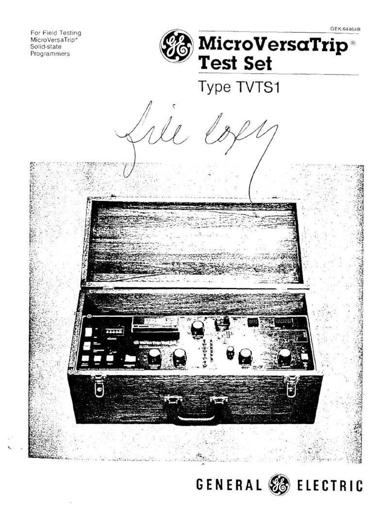
GE POWER-BREAK TAK-TS1 User manual

GEI
-
86158
U
\
J
\
J
I I
U
Li
I
—
SU
Li
J
\
U
—
UU
LA
VJfcfl
ItflUl
Circuit
Protective
Devices
Department
—
Plainville
,
Connecticut
06062
\
f
^
oiniy
1
IVIUU
.
£
.
tAiSfh
vvin
i
Test
Set
Cat
No
.
TAK
-
TS
1
r
\
n
ii
u
J
-
l
i
—
l
r
?
u
n
n
!
NS
?
«
n
:
i
:
TW
!
NS
G
|
K
«
S
*
LOCKOUT
<
g
/
t
ir
o
n
n
i
-
i
WWW
Wftf
Maw
tM
*
•
mrm
'
tm
*
mu
*
WWTtMH
_
<
OMSMIL
*
U
»
IW
«
1
«
FAULT
TRIP
T
INDICATORS
urtm
*
u
?
*
au
*
1
AT
0
«
*
W
‘
«
mvu
»
wu
MMU
acini
»
»
w
»
SE
;
O
QAOUND
FAULT
!
It
i
H I
I I
9
1 1
M
I
-
II
mi
SHORT
CIRCUIT
'
u
u
OVERLOAD
s
5
*
IMH
NumfiK
These
instructions
do
not
purport
to
cover
all
details
or
variations
in
equipment
nor
to
provide
for
every
possible
contingency
to
be
met
in
connection
with
installation
,
operation
or
maintenance
.
Should
further
information
be
desired
or
should
particular
problems
arise
which
are
not
covered
sufficiently
for
the
purchaser
'
s
purposes
,
the
matter
should
be
referred
to
the
General
Electric
Company
.
Courtesy of NationalSwitchgear.com

CONTENTS
Page
3
INTRODUCTION
Solid
-
state
Programmer
Unit
Only
—
Mode
"
A
"
Complete
Trip
Device
System
—
Mode
"
B
"
. .
3
3
3
SPECIFICATIONS
3
APPLICABLE
TIME
-
CURRENT
CURVES
3
OPERATING
CONTROLS
ON
-
OFF
Switch
Trip
Breaker
—
Programmer
Only
Switch
.
.
.
Test
Selector
Programmer
Long
-
time
Pickup
Setting
Selector
Current
Adjust
Knob
Pre
-
set
Current
Button
Start
Button
Test
Indicator
Trip
Indicator
Reset
Button
Phase
Sensor
Continuity
Test
Test
-
current
Meter
Elapsed
Time
Meter
Test
Set
Lock
-
out
Indicator
External
Monitor
Jacks
,
Test
Set
Accuracy
.
.
4
4
4
4
4
4
4
5
5
5
5
5
5
5
5
6
CONNECTING
THE
TEST
SET
Safety
Precautions
Connections
Programmer
Only
Test
—
Mode
"
A
”
Complete
System
Test
—
Mode
"
B
"
6
6
6
7
7
PRELIMINARY
TEST
PROCEDURE
FUNCTIONAL
TESTS
Long
-
time
Pickup
Test
...
Long
-
time
Delay
Test
.
..
.
Short
-
time
Pickup
Test
.
.
.
Short
-
time
Delay
Test
..
.
Instantaneous
Pickup
Test
Ground
Fault
Pickup
Test
Ground
Fault
Time
-
delay
Test
Phase
Sensor
Continuity
Test
Fault
Trip
Indicators
.
.
.
.
8
9
10
11
12
13
14
14
15
15
IF
TEST
RESULTS
DO
NOT
CONFORM
15
COMPLETION
OF
TESTS
16
,
17
SCHEMATIC
,
PARTS
LIST
.
SIMPLIFIED
SCHEMATIC
,
CIRCUIT
DESCRIPTION
18
2
Courtesy of NationalSwitchgear.com

TESTING
VERSATRIP
MODEL
2
WITH
TEST
SET
,
CAT
.
NO
.
TAK
-
TS
1
,
G
El
-
86158
INTRODUCTION
SOLID
-
STATE
PROGRAMMER
UNIT
ONLY
-
MODE
"
A
"
Test
Set
TAK
-
TS
1
is
a
portable
instrument
designed
for
field
testing
the
performance
of
Types
SST
and
ECS
solid
-
state
overcurrent
trip
devices
.
Test
Scope
1
.
Verify
the
time
-
current
characteristics
and
pickup
calibration
of
the
various
trip
elements
.
Designations
for
the
trip
elements
are
abbreviated
as
follows
:
The
purpose
of
these
instructions
is
to
extend
the
usefulness
of
the
TAK
-
TS
1
Test
Set
so
that
it
may
also
be
used
to
test
VersaTrip
Model
2
solid
-
state
trip
devices
.
It
may
not
be
used
to
test
earlier
VersaTrip
model
types
.
LT
—
Long
Time
ST
—
Short
Time
INST
—
Instantaneous
G
F
—
Ground
Fault
Following
are
a
list
of
components
which
com
-
prise
the
complete
trip
device
system
:
2
.
Verify
operation
of
the
fault
-
trip
indicators
on
Programmer
units
so
equipped
.
1
.
Solid
-
state
Programmer
Unit
2
.
Phase
Current
Sensors
3
.
Flux
Shift
Magnetic
Trip
Device
4
.
Fourth
-
wire
Neutral
Sensor
for
units
con
-
taining
a
Ground
Fault
trip
element
for
use
on
three
-
phase
,
four
-
wire
load
circuits
.
COMPLETE
TRIP
DEVICE
SYSTEM
-
MODE
"
B
"
Test
Scope
1
.
Perform
all
programmer
tests
previously
de
-
scribed
,
plus
the
provision
to
activate
the
Flux
Shift
Magnetic
Trip
Device
to
verify
its
operation
by
physically
tripping
the
breaker
.
All
components
,
except
the
Neutral
Sensor
,
are
mounted
integral
to
the
circuit
breaker
.
When
used
,
the
Neutral
Sensor
is
separately
mounted
in
the
bus
or
cable
compartment
of
the
switchgear
.
In
drawout
construction
,
it
is
automatically
con
-
nected
to
the
trip
device
on
the
breaker
via
a
drawout
secondary
disconnect
block
.
2
.
Check
continuity
of
the
Phase
Sensors
.
SPECIFICATIONS
Input
:
105
-
125
Vac
50
/
60
Hz
Power
Consumption
:
150
watts
maximum
Weight
:
20
pounds
Dimensions
:
15
in
.
L
x
9
in
.
H
x
9
3
/
4
in
.
D
The
TAK
-
TS
1
Test
Set
is
used
to
perform
the
various
trip
device
tests
in
two
basic
modes
:
"
A
"
—
Solid
State
Programmer
Unit
Only
"
B
"
—
Complete
Trip
Device
System
APPLICABLE
TIME
-
CURRENT
CURVES
WARNING
:
THESE
TESTS
CAN
BE
CONDUCTED
ONLY
ON
A
DEEN
-
ERGIZED
BREAKER
-
ONE
WHICH
IS
COMPLETELY
DISCONNECTED
FROM
ITS
PRIMARY
AND
CONTROL
POWER
SOURCES
.
VersaTrip
MOD
2
LT
,
ST
+
INST
-
GES
-
6184
,
-
6186
,
-
6187
,
and
-
6188
VersaTrip
MOD
2
Ground
Fault
—
GES
-
6185
,
-
6189
,
-
6190
,
and
-
6191
OPERATING
CONTROLS
All
tests
are
conducted
with
the
programmer
plug
disconnected
from
the
breaker
.
It
may
be
necessary
to
remove
the
programmer
from
the
breaker
to
gain
access
to
its
test
plug
.
The
Test
Set
indicators
and
operating
controls
are
identified
on
the
front
panel
arrangement
shown
in
Fig
.
1
and
described
on
pages
4
and
5
.
3
Courtesy of NationalSwitchgear.com

GE
1
-
86158
,
TESTING
VERSATRIP
MODEL
2
WITH
TEST
SET
,
CAT
.
NO
.
TAK
-
TS
1
Fig
.
1
.
Front
panel
of
Test
Set
TAK
-
TSi
PROGRAMMER
LONG
-
TIME
PICKUP
SETTING
SELECTOR
ON
-
OFF
SWITCH
Applies
115
Vac
input
power
to
the
test
set
.
A
red
companion
LED
indicator
,
located
directly
above
,
illuminates
when
the
switch
is
in
the
ON
position
.
Protection
is
provided
by
a
one
ampere
fuse
,
located
above
the
indicator
light
.
Establishes
a
test
-
current
magnitude
consistent
with
,
and
specifically
for
,
each
continuous
ampere
setpoint
on
the
programmer
.
For
all
phase
current
testing
(
LT
,
ST
and
INST
elements
)
,
the
position
of
this
control
must
match
the
continuous
ampere
setting
on
the
programmer
.
TRIP
BREAKER
-
PROGRAMMER
ONLY
SWITCH
CURRENT
ADJUST
KNOB
Provides
a
choice
of
two
test
modes
:
A
variable
transformer
for
establishing
the
de
-
sired
level
of
test
current
to
be
applied
to
the
programmer
.
Programmer
Only
Position
—
Mode
"
A
"
The
programmer
'
s
trip
signal
output
is
confined
to
the
test
set
circuitry
and
cannot
trip
the
breaker
.
PRE
SET CURRENT
BUTTON
Trip
Breaker
Position
—
Mode
"
B
"
Enables
the
operator
to
pre
-
establish
(
via
the
CURRENT
ADJUST
control
)
the
desired
test
current
prior
to
initiating
a
test
.
For
this
control
to
function
,
the
programmer
unit
must
be
connected
to
the
test
set
.
The
programmer
'
s
trip
signal
output
is
directed
to
the
circuit
breaker
'
s
magnetic
trip
device
to
physically
trip
the
breaker
.
This
mode
establishes
the
integrity
of
the
magnetic
trip
device
and
the
programmer
'
s
capability
to
actuate
it
.
START
BUTTON
TEST
SELECTOR
Initiates
the
test
run
by
applying
current
to
the
programmer
.
The
current
persists
until
the
unit
trips
or
the
RESET
button
is
actuated
.
Positioned
according
to
the
type
of
test
desired
—
Phase
Current
A
,
B
,
C
,
or
GROUND
FAULT
.
4
Courtesy of NationalSwitchgear.com

TESTING
VERSATRIP
MODEL
2
WITH
TEST
SET
,
CAT
.
NO
.
TAK
-
TS
1
,
G
El
-
86158
circuit
is
provided
.
This
circuit
monitors
the
current
-
time
input
to
the
programmer
such
that
when
a
predetermined
limit
is
exceeded
,
the
Test
Set
becomes
inoperative
for
a
period
of
approxi
-
mately
70
seconds
.
It
then
automatically
resets
to
its
normal
operating
state
.
A
lock
-
out
condition
exists
whenever
the
TEST
SET
LOCK
-
OUT
in
-
dicator
is
lit
.
TEST
INDICATOR
This
LED
lights
whenever
the
PRE
-
SET
CUR
-
RENT
or
START
controls
are
activated
.
TRIP
INDICATOR
An
LED
which
,
when
lit
,
indicates
that
an
acceptable
trip
signal
has
been
delivered
by
the
programmer
.
Conversely
,
a
trip
not
accompanied
by
the
light
signifies
that
the
trip
signal
amplitude
is
too
low
.
Upon
completion
of
a
test
,
the
TRIP
indicator
stays
lit
until
the
RESET
button
is
depressed
.
EXTERNAL
MONITOR
JACKS
,
TEST
SET
ACCURACY
The
test
-
current
values
displayed
on
the
Test
Current
Meter
are
accurate
to
within
±
3
percent
of
the
meter
reading
.
These
limits
are
contingent
upon
a
clean
sine
wave
input
voltage
to
the
Test
Set
.
Wave
distortion
can
cause
additional
error
.
RESET
BUTTON
Resets
the
Test
Set
logic
so
that
a
new
test
sequence
can
be
initiated
.
It
also
stops
a
test
in
progress
.
Should
greater
accuracy
be
desired
,
provision
is
made
for
connecting
external
instruments
via
the
EXTERNAL
MONITOR
jacks
on
the
front
panel
.
These
jacks
are
connected
across
an
isolated
,
precision
0.2
-
ohm
resistor
in
series
with
the
test
current
circuit
.
Output
at
these
jacks
is
shown
in
Table
1
.
PHASE
SENSOR
CONTINUITY
TEST
This
section
of
the
panel
contains
controls
for
checking
electrical
continuity
of
each
phase
sensor
circuit
.
The
selector
determines
the
phase
to
be
tested
.
Proper
continuity
exists
when
the
OK
LED
indicator
lights
up
when
the
PUSH
TO
TEST
button
is
depressed
.
No
light
signifies
that
a
high
resistance
or
open
circuit
exists
in
the
CT
or
its
wiring
harness
(
see
Note
3
,
page
14
)
.
The
EXTERNAL
MONITOR
jacks
may
also
be
employed
,
in
conjunction
with
a
storage
oscillo
-
scope
,
for
more
accurate
measurement
of
trip
times
.
For
trip
times
in
the
range
of
less
than
one
second
,
the
Test
Set
'
s
time
meter
can
provide
only
a
single
digit
approximation
(
nearest
0.1
second
)
.
TEST
-
CURRENT
METER
Provides
digital
readout
of
the
normalized
test
-
current
level
being
applied
to
the
Programmer
Unit
.
It
is
never
necessary
to
calculate
a
test
-
current
value
.
TABLE
I
EXTERNAL
MONITOR
OUTPUT
TEST
SET
CONTROL
POSITIONS
AC
MILLIVOLTS
PER
TEST
CURRENT
UNIT
(
±
1
%
)
ELAPSED
TIME
METER
A
mechanical
counter
which
records
the
pro
-
grammer
'
s
tripping
time
,
in
seconds
and
tenths
.
It
must
be
manually
reset
after
completion
of
each
test
.
PROGRAMMER
LONG
TIME
PICKUP
SETTING
TEST
SELECTOR
0.6
X
60
0.7
X
70
0
A
,
0
B
or
0
C
0.8
X
80
NOTE
:
When
operating
the
Test
Set
from
a
50
-
Hz
supply
,
readings
of
the
Elapsed
Time
Meter
must
be
multiplied
by
a
1.2
factor
.
0.9
X
90
1.0
X
100
1.1
X
110
GROUND
FAULT
(
Not
Applicable
)
100
TEST
SET
LOCK
-
OUT
INDICATOR
To
prevent
possible
damage
to
the
Programmer
Unit
when
subjected
to
abnormally
prolonged
or
continuous
testing
at
high
-
current
levels
,
a
lock
-
out
EXAMPLE
:
The
external
monitor
output
,
with
a
programmer
long
-
time
pickup
setting
of
0.7
X
and
a
Test
-
Current
Meter
reading
of
6.00
=
70
x
6.00
=
420
mv
±
1
percent
.
5
Courtesy of NationalSwitchgear.com

GEI
-
86158
,
TESTING
VERSATRIP
MODEL
2
WITH
TEST
SET
,
CAT
.
NO
.
TAK
-
TS
1
.
MALE
*
ir
BREAKER
HARNESS
TO
CURRENT
SENSORS
AND
MAGNETIC
TRIP
DEVICE
^
.
FEMALE
*
NOTE
‘
THE
PROGAMMER
PLUG
LOCATION
WILL
VARY
DEPENDING
ON
BREAKER
FRAME
SIZE
.
IT
IS
LOCATED
EITHER
ON
THE
BACK
OR
THE
SIDE
PANEL
OF
THE
PROGRAMMER
BOX
.
PROGRAMMER
UNIT
S
I
DE
VIEW
Fig
.
2
.
Normal
in
-
service
breaker
connection
CONNECTING
CONNECTIONS
TUE
TEST
EET
ns
i
LJ
i
SAFETY
PRECAUTIONS
NOTE
:
Before
proceeding
with
the
follow
-
ing
connection
work
,
ensure
that
the
Test
Set
power
supply
cord
is
not
connected
.
WARNING
:
BEFORE
CONNECTING
THE
TEST
SET
TO
THE
BREAKER
TRIP
DEVICE
SYSTEM
,
ENSURE
THAT
THE
CIRCUIT
BREAKER
IS
COMPLETELY
"
PROGRAMMER
ONLY
"
TEST
-
MODE
"
A
"
(
SEE
FIG
.
3
)
DISCONNECTED
FROM
ITS
POWER
SOURCE
.
ON
DR
AW
OUT
EQUIPMENT
,
RACK
THE
BREAKER
TO
ITS
DISCON
-
NECTED
POSITION
.
VERIFY
THAT
THE
BREAKER
iS
TRiPPED
.
1
.
Remove
breaker
cover
and
Programmer
Unit
.
2
.
Disconnect
the
breaker
harness
from
the
Programmer
Unit
.
CAUTION
:
NEVER
DISENGAGE
THE
3
.
Plug
the
Test
Set
female
connector
lead
to
the
receptacle
on
the
rear
of
the
programmer
.
HARNESS
CONNECTOR
FROM
THE
PROGRAMMER
UNIT
ON
A
BREAKER
THAT
IS
ENERGIZED
AND
CARRYING
LOAD
CURRENT
.
THIS
WILL
OPEN
-
CIRCUIT
THE
CURRENT
SENSORS
,
ft
II
/
-
H U
/
/
X I
MLLUVVUMLl
4
.
The
Test
Set
male
connector
lead
need
not
be
connected
to
the
breaker
harness
for
"
Programmer
Only
"
testing
.
However
,
the
Fig
.
4
connection
should
be
used
if
"
Complete
System
"
tests
are
to
be
run
also
.
M
-
n
A
Mr
'
ror
*
1
;
°
A
r t
n
A
UMivv
E
nuuo
s
-
uvis
ur
-
\
i
VOLTAGES
TO
DEVELOP
.
SEE
AmMn
/
1
U
/
/
VU
FIG
.
2
.
TEST
SET
MALE
CONNECTOR
(
NOT
USED
)
TAK
"
TSi
TEST
SET
Fig
.
3
.
Connection
for
"
Programmer
Only
"
test
6
Courtesy of NationalSwitchgear.com

TESTING
VERSA
TRIP
MODEL
2
WITH
TEST
SET
,
CAT
.
NO
.
TAK
-
TS
1
,
G
El
-
86158
BREAKER
HARNESS
l
TEST
SET
LEADS
TAK
-
TSI
TEST
SET
^
OAC
SOURCE
*
NOTE
:
THE
PROGAMMER
PLUG
LOCATION
WILL
VARY
DEPENDING
ON
BREAKER
FRAME
SIZE
.
IT
IS
LOCATED
EITHER
ON
THE
BACK
OR
THE
SIDE
PANEL
OF
THE
PROGRAMMER
BOX
.
Fig
.
4
.
Connection
for
Complete
System
test
"
COMPLETE
SYSTEM
"
TEST
-
MODE
"
B
"
(
SEE
FIG
.
4
)
TRIP
BREAKER
-
PROGRAMMER
ONLY
:
As
desired
.
1
.
Remove
breaker
cover
and
Programmer
Unit
.
PROGRAMMER
LONG
-
TIME
PICKUP
SET
-
TING
:
Position
this
knob
identical
to
the
programmer
'
s
continuous
ampere
setting
.
2
.
Disconnect
the
breaker
harness
from
the
Programmer
Unit
and
reconnect
its
female
con
-
nector
to
the
male
connector
lead
from
the
Test
Set
.
2
.
Record
the
"
In
Service
"
settings
of
the
programmer
so
that
its
set
points
can
be
restored
upon
completion
of
testing
.
3
.
Plug
the
Test
Set
female
connector
lead
into
the
receptacle
on
the
programmer
.
4
.
Breakers
with
VersaTrip
MOD
2
are
provided
with
programmer
position
interlocks
.
These
must
be
bypassed
and
the
breaker
cover
replaced
to
also
test
the
Flux
Shift
Device
.
3
.
Connect
the
Test
Set
power
cord
to
the
105
-
125
Vac
power
source
.
4
.
Turn
power
ON
.
5
.
Push
the
START
button
.
The
Elapsed
Time
Meter
will
start
to
run
and
the
TEST
indicator
should
light
and
remain
lit
.
PRELIMINARY
TEST
PROCEDURE
The
following
steps
should
be
conducted
before
starting
functional
tests
.
6
.
Push
the
RESET
button
.
The
Elapsed
Time
Meter
will
stop
and
the
TEST
indicator
light
will
go
out
.
1
.
Position
the
Test
Set
controls
as
follows
:
7
.
Mechanically
reset
the
Elapsed
Time
Meter
.
Functional
testing
,
described
individually
for
each
trip
element
in
subsequent
pages
,
may
now
begin
.
CURRENT
ADJUST
:
Rotate
to
zero
TEST
SELECTOR
:
0
A
7
Courtesy of NationalSwitchgear.com

GEI
-
86158
,
TESTING
VERSATR
/
P
MODEL
2
WITH
TEST
SET
,
CAT
.
NO
.
TAK
-
TS
1
Preset
CURRENT
LEVEL
to
the
trip
current
shown
in
Table
2
.
LONG
-
TIME
PICKUP
TEST
PURPOSE
2
.
Reset
timer
and
RESET
button
.
Verify
that
pickup
occurs
within
tolerance
.
For
any
given
pickup
setting
,
this
is
achieved
in
two
steps
:
3
.
Push
START
.
Allow
test
to
run
until
unit
trips
.
The
time
meter
reading
should
conform
to
Table
2
limits
.
For
50
-
Hz
operation
,
multiply
timer
readings
by
1.2
.
I
.
Test
for
NO
PICKUP
at
a
current
value
slightly
below
the
published
lower
tolerance
limit
.
See
Note
1
.
If
unit
does
not
trip
within
the
specified
time
,
repeat
the
test
carefully
monitoring
and
read
-
justing
the
test
current
as
necessary
.
Transient
dips
in
the
supply
voltage
could
lower
the
test
signal
current
below
its
pickup
value
,
causing
the
programmer
'
s
timing
circuit
to
reset
.
2
.
Test
for
PICKUP
at
a
current
value
slightly
above
the
published
upper
tolerance
limit
.
See
Note
2
.
Repeat
PICKUP
and
NO
PICKUP
tests
on
the
other
phases
.
PROCEDURE
NO
PICKUP
TABLE
2
1
.
Programmer
settings
:
LONG
TIME
PICKUP
VERSATRIP
MODEL
2
PROGRAMMERS
LONG
-
TIME
DELAY
-
set
on
MIN
band
.
TEST
CURRENT
The
I
NT
or
MAX
bands
may
be
used
if
desired
.
TEST
LIMITS
TIME
IN
SECONDS
SENSOR
AMP
RATING
*
MODE
MAX
BAND
2000
A
OR
MORE
INT
MIN
1600
A
OR
LESS
2
.
Position
Test
Set
controls
:
BAND
BAND
PROGRAMMER
LONG
-
TIME
PICKUP
SET
-
TING
—
Must
match
the
programmer
'
s
con
-
tinuous
ampere
setting
.
1000
500
250
1.00
NOTRIP
0.50
<
800
<
400
<
200
1.30
TRIP
0.65
TEST
SELECTOR
-
<
/
>
A
,
B
or
C
*
The
sensor
amp
rating
is
shown
on
the
face
of
the
programmer
being
tested
.
TEST
CURRENT
-
Preset
the
NO
TRIP
test
current
shown
in
Table
2
.
NOTE
:
7
.
Lower
test
limits
are
extended
below
the
published
pickup
tolerance
to
allow
for
Test
Set
accuracy
.
3
.
Reset
timer
and
RESET
button
.
4
.
Push
START
—
Allow
test
to
run
until
time
delay
of
Table
2
has
expired
.
Unit
should
NOT
trip
.
For
50
-
Hz
operation
,
multiply
timer
readings
by
1.2
.
NOTE
:
2
.
Upper
test
limits
exceed
the
published
pickup
tolerance
to
allow
for
Test
Set
accuracy
plus
nominal
dips
in
Test
Set
supply
voltage
.
During
testing
,
the
test
current
should
be
monitored
and
adjusted
,
if
necessary
.
PICKUP
1
.
Position
Test
Set
controls
—
Same
as
NO
PICKUP
,
Step
2
,
except
:
If
test
results
do
not
conform
,
see
page
15
.
8
Courtesy of NationalSwitchgear.com

TESTING
VERSATRIP
MODEL
2
WITH
TEST
SET
,
CAT
NO
.
TAK
-
TS
1
,
G
El
-
86158
LONG
-
TIME
DELAY
TEST
NOTE
:
These
values
must
be
below
the
short
time
and
instantaneous
pickup
set
-
tings
on
the
programmer
,
otherwise
a
pre
-
mature
trip
signal
will
be
received
from
those
functions
.
PURPOSE
Verify
that
the
LT
characteristic
conforms
to
its
upper
and
lower
band
limits
.
This
test
requires
measurement
of
delay
times
at
three
different
values
of
test
current
.
2
.
Reset
timer
and
RESET
button
.
3
.
Push
START
.
Allow
test
to
run
until
trip
occurs
.
TIME
meter
reading
should
conform
to
Table
3
limits
.
For
50
-
Hz
operation
,
multiply
timer
readings
by
1.2
.
PROCEDURE
1
.
Position
Test
Set
controls
:
4
.
Repeat
the
above
test
at
the
other
two
test
values
.
This
step
verifies
the
linearity
of
the
T
-
C
characteristic
.
PROGRAMMER
LONG
-
TIME
PICKUP
SET
-
TING
—
Must
match
the
programmer
'
s
con
-
tinuous
ampere
setting
.
5
.
Repeat
the
test
on
the
other
phases
at
one
test
value
.
TEST
SELECTOR
-
0
A
,
B
,
or
C
TEST
CURRENT
-
From
Table
3
,
select
three
test
-
current
values
.
Preset
the
first
value
.
Repeat
the
above
test
series
on
the
other
delay
bands
.
TABLE
3
LONG
TIME
DELAY
VERSATRIP
MODEL
2
PROGRAMMERS
TEST
CURRENT
SENSOR
AMP
RATING
*
2000
A
OR
MORE
TEST
LIMITS
!
TIME
IN
SECONDS
X
INT
MAX
BAND
1600
A
OR
LESS
MIN
VALUE
BAND
BAND
1.5
X
0.75
1.50
60.2
-
101.8
33.8
-
57.3
15.0
-
25.5
8.4
-
14.3
5.4
-
9.2
3.7
-
6.4
2.7
-
4.7
2.1
-
3.6
120.0
-
203.7
67.7
-
114.6
30.1
-
50.9
16.9
-
28.6
10.8
-
18.3
7.5
-
12.7
5.5
-
9.3
4.2
-
7.2
240.8
-
407.4
135.4
-
229.2
60.2
-
101.8
33.8
-
57.3
21.6
-
36.7
15.0
-
25.5
11.0
-
18.7
8.4
-
14.3
2
.
OX
1.00
2.00
3
.
OX
1.50
3.00
4
.
OX
2.00
4.00
5
.
OX
2.50
5.00
6
.
OX
3.00
6.00
7
.
OX
3.50
7.00
8
.
OX
4.00
8.00
*
The
sensor
amp
rating
is
shown
on
the
face
of
the
programmer
being
tested
.
tReflecting
the
±
3
percent
Test
Set
accuracy
,
al
!
test
limits
are
extended
beyond
the
published
band
limits
of
the
time
-
current
curves
.
During
testing
,
the
test
current
should
be
monitored
and
readjusted
if
necessary
.
If
test
results
do
not
conform
,
see
page
15
.
9
Courtesy of NationalSwitchgear.com

GE
1
-
86158
,
TESTING
VERSATRIP
MODEL
2
WITH
TEST
SET
,
CAT
.
NO
.
TAK
-
TSI
SHORT
-
TIME
PICKUP
TEST
4
.
Push
START
.
The
unit
must
trip
in
less
than
one
second
,
as
indicated
by
the
timer
.
For
50
-
Hz
operation
,
multiply
timer
readings
by
1.2
.
PURPOSE
Verify
that
pickup
occurs
within
tolerance
.
This
requires
two
tests
at
any
desired
pickup
setting
—
one
for
pickup
at
the
upper
tolerance
limit
,
the
second
for
no
pickup
at
the
lower
tolerance
limit
.
ACTUAL
PICKUP
VALUE
(
if
desired
)
-
Starting
at
the
lower
tolerance
limit
(
Table
4
)
,
test
incremental
increases
in
test
current
until
a
trip
occurs
in
less
than
one
second
,
as
indicated
by
the
timer
.
Push
the
PRE
-
SET
CURRENT
button
,
read
the
actual
pickup
value
.
PROCEDURE
PICKUP
1
.
Programmer
settings
:
NO
PICKUP
1
.
Programmer
settings
—
Same
as
PICKUP
,
Step
1
.
ST
DELAY
BAND
-
As
desired
.
INST
PICKUP
—
Must
be
set
higher
than
the
ST
pickup
setting
,
otherwise
the
unit
will
trip
first
on
INST
mode
.
2
.
Position
Test
Set
controls
—
Same
as
PICKUP
,
Step
2
except
:
2
.
Position
Test
Set
controls
:
TEST
CURRENT
—
Preset
the
lower
test
-
current
limit
from
Table
4
.
PROGRAMMER
LONG
TIME
PICKUP
SET
-
TING
—
Must
match
the
programmer
'
s
con
-
tinuous
ampere
setting
.
TEST
SELECTOR
-
4
>
A
,
B
,
or
C
TEST
CURRENT
current
limit
from
Table
4
.
3
.
Push
START
.
The
unit
must
not
trip
in
less
than
one
second
.
However
,
a
trip
may
occur
after
one
second
due
to
a
signal
from
the
LT
element
.
For
50
-
Hz
operation
,
multiply
timer
readings
by
\
.
,
,
s
Preset
an
upper
test
-
1.2
.
Repeat
PICKUP
and
NO
PICKUP
tests
for
at
least
one
setting
on
each
of
the
other
phases
.
3
.
Reset
timer
and
RESET
button
.
TABLE
4
SHORT
-
TIME
PICKUP
VERSATRIP
MODEL
2
PROGRAMMERS
TEST
CURRENT
SENSOR
AMPERE
RATING
*
1600
AOR
LESS
SENSOR
AMPERE
RATING
*
2000
A
OR
MORE
PRO
-
GRAMMER
PICKUP
SETTING
60
HZ
50
HZ
60
HZ
50
HZ
LOWER
LIMIT
(
NOTRIP
)
UPPER
LIMIT
(
TRIP
)
LOWER
LIMIT
(
NOTRIP
)
UPPER
LIMIT
(
TRIP
)
LOWER
LIMIT
(
NO
TRIP
)
UPPER
LIMIT
(
TRIP
)
LOWER
LIMIT
(
NO
TRIP
)
UPPER
LIMIT
(
TRIP
)
1.65
1.70
1.30
1.27
0.63
0.82
0.85
0.65
1.5
1.69
2.20
2.27
1.10
1.75
1.13
0.84
0.87
2
2.11
2.83
2.75
1.37
2.18
1.05
1.42
1.09
2.5
3.30
2.54
2.61
3.40
1.27
1.65
1.30
1.70
3
4.40
4.54
3.39
2.20
3.49
1.69
1.74
2.27
4
4.24
5.50
5.67
4.36
2.11
2.75
2.83
2.18
5
6.59
5.08
5.23
6.80
2.54
3.30
3.40
2.61
6
5.92
7.69
7.93
2.96
3.85
6.11
3.97
3.05
7
9.07
6.78
8.79
3.38
4.40
6.98
3.49
4.53
8
*
The
sensor
ampere
rating
is
shown
on
the
face
of
the
programmer
being
tested
.
If
test
results
do
not
conform
,
see
page
15
.
10
Courtesy of NationalSwitchgear.com

TESTING
VERSATRIP
MODEL
2
WITH
TEST
SET
,
CAT
.
NO
.
TAK
-
TS
1
,
GE
/
-
86
I
58
SHORTTiME
DELAY
TEST
TEST
CURRENT
value
two
steps
higher
than
the
programmer
'
s
CT
pickup
setting
(
e
.
g
.
,
preset
5.0
for
a
3
X
pickup
setting
)
.
This
avoids
measurement
at
the
knee
of
the
time
-
current
curve
,
.
where
the
time
delay
may
be
longer
than
the
band
limits
given
in
Table
5
.
Preset
a
test
-
current
PURPOSE
U
I
Provide
an
approximate
indication
that
time
delay
occurs
within
the
time
band
selected
.
Due
to
the
small
time
magnitudes
involved
(
0.5
seconds
or
less
)
,
the
timer
'
s
right
digit
provides
only
a
rough
approximation
of
the
actual
trip
time
.
If
a
more
accurate
reading
is
desired
,
the
EXTERNAL
MONITOR
jacks
may
be
employed
as
described
previously
in
OPERATING
CONTROLS
.
3
.
Reset
timer
and
RESET
button
.
4
.
Push
START
.
Observe
trip
time
.
Repeat
the
above
test
on
the
other
time
bands
,
then
check
at
least
one
band
on
each
of
the
other
phases
.
PROCEDURE
1
.
Programmer
settings
:
TABLE
5
INST
PICKUP
—
Use
maximum
setting
SHORTTIME
DELAY
SHORT
-
TIME
PICKUP
setting
Use
minimum
PUBLISHED
BAND
LIMITS
TiME
IN
SECONDS
BAND
LOWER
UPPER
2
.
Position
Test
Set
controls
:
MIN
0.095
0.21
0.17
I
NT
PROGRAMMER
LONG
-
TIME
PICKUP
SET
-
TING
—
Must
match
the
programmer
'
s
con
-
tinuous
ampere
setting
.
0.30
MAX
A
Or
-
0.48
u
.
oo
TEST
SELECTOR
-
0
A
,
B
,
or
C
If
test
results
do
not
conform
,
see
page
15
.
11
Courtesy of NationalSwitchgear.com

G
El
-
86158
,
TESTING
VERSATRIP
MODEL
2
WITH
TEST
SET
,
CAT
.
NO
.
TAK
-
TS
1
ACTUAL
PICKUP
VALUE
(
if
desired
)
-
INSTANTANEOUS
PICKUP
TEST
Starting
at
the
lower
tolerance
limit
(
Table
6
)
,
test
incremental
increases
in
test
current
until
an
INST
trip
occurs
(
no
discernible
timer
movement
)
.
Push
the
PRESET
CURRENT
button
,
read
the
actual
pickup
value
.
PURPOSE
Verify
that
pickup
occurs
within
tolerance
.
This
requires
two
tests
at
a
given
pickup
setting
—
one
for
pickup
at
the
upper
tolerance
limit
,
the
second
for
no
pickup
at
the
lower
tolerance
limit
.
NO
PICKUP
PROCEDURE
1
.
Position
Test
Set
controls
—
Same
as
PICKUP
,
Step
1
,
except
:
PICKUP
1
.
Position
Test
Set
controls
:
TEST
CURRENT
current
limit
from
Table
6
.
Preset
the
lower
test
-
PROGRAMMER
LONG
-
TIME
PICKUP
SET
-
TING
-
Must
match
the
programmer
'
s
con
-
tinuous
ampere
setting
.
2
.
Push
START
.
The
unit
must
not
trip
instanta
-
neously
(
as
in
PICKUP
,
Step
3
)
—
the
INST
element
is
not
activated
at
these
lower
limit
values
.
However
,
the
unit
is
subject
to
and
will
respond
to
a
time
-
delayed
trip
signal
from
the
LT
element
.
Also
,
if
so
equipped
,
it
responds
to
any
ST
element
whose
pickup
is
set
below
the
INST
setting
.
In
either
event
,
the
delayed
trip
produces
definite
movement
of
the
timer
,
a
positive
indication
that
the
unit
did
not
trip
via
the
INST
mode
.
TEST
SELECTOR
-
0
A
,
B
,
or
C
Preset
an
upper
test
-
TEST
CURRENT
current
limit
from
Table
6
.
2
.
Reset
timer
and
RESET
button
.
3
.
Push
START
.
The
unit
must
trip
immediately
indicated
by
little
or
no
discernible
timer
movement
.
Repeat
PICKUP
and
NO
PICKUP
tests
for
at
least
one
setting
on
each
of
the
other
phases
.
as
TABLE
6
INSTANTANEOUS
PICKUP
VERSATRIP
MODEL
2
PROGRAMMERS
TEST
CURRENT
SENSOR
AMPERE
RATING
*
2000
A
OR
MORE
SENSOR
AMPERE
RATING
*
1600
A
0
R
LESS
PRO
-
GRAMMER
PICKUP
SETTING
50
HZ
60
HZ
50
HZ
60
HZ
UPPER
LIMIT
(
TRIP
)
LOWER
LIMIT
(
NO
TRIP
)
LOWER
LIMIT
(
NO
TRIP
)
UPPER
LIMIT
(
TRIP
)
UPPER
LIMIT
(
TRIP
)
UPPER
LIMIT
(
TRIP
)
LOWER
LIMIT
(
NO
TRIP
)
LOWER
LIMIT
(
NOTRIP
)
0.84
1.10
1.74
1.69
2.20
2
X
1.13
2.27
0.87
1.37
2.18
2.83
2.11
2.75
1.09
1.42
1.05
2.5
X
1.65
2.60
3.40
2.54
3.30
1.70
1.27
1.30
3
X
3.39
4.40
3.49
4.54
1.69
2.20
1.74
2.27
4
X
4.24
5.50
2.83
2.11
4.36
5.67
5
X
2.18
2.75
5.08
6.59
2.54
5.23
6.80
2.61
3.40
3.30
6
X
7.93
5.92
7.69
3.97
2.96
3.85
6.11
7
X
3.05
6.78
8.79
4.53
3.38
4.40
6.98
9.07
8
X
3.49
4.23
8.73
11.33
8.47
10.99
4.36
5.67
5.50
10
X
*
The
sensor
ampere
rating
is
shown
on
the
face
of
the
programmer
being
tested
.
If
test
results
do
not
conform
,
see
page
15
.
12
Courtesy of NationalSwitchgear.com

TESTING
VERSATR
/
P
MODEL
2
WITH
TEST
SET
,
CAT
NO
.
TAK
-
TS
1
,
G
El
-
86158
GROUND
FAULT
PICKUP
TEST
ACTUAL
PICKUP
VALUE
(
if
desired
)
-
PURPOSE
Starting
at
the
lower
limit
(
Table
7
)
,
test
in
-
cremental
increases
in
Test
Current
until
a
trip
occurs
in
less
than
one
second
,
as
indicated
by
the
timer
.
Push
the
PRESET
CURRENT
button
,
read
the
actual
pickup
value
.
Verify
that
pickup
occurs
within
tolerance
.
Two
tests
are
required
at
a
given
pickup
setting
—
one
for
pickup
at
the
upper
tolerance
limit
,
the
second
for
no
pickup
at
the
lower
tolerance
limit
.
NO
PICKUP
PROCEDURE
1
.
Position
Test
Set
Controls
—
Same
as
PICK
-
UP
,
Step
1
except
:
PICKUP
1
.
Position
Test
Set
controls
:
Preset
the
lower
test
-
TEST
CURRENT
current
limit
from
Table
7
.
TEST
SELECTOR
-
Ground
Fault
2
.
Reset
timer
and
RESET
button
.
TEST
CURRENT
current
limit
from
Table
7
.
Preset
an
upper
test
-
3
.
Push
START
.
The
unit
should
not
trip
,
timer
will
read
greater
than
one
second
delay
.
Discon
-
tinue
the
test
after
one
second
.
If
the
test
is
allowed
to
run
longer
than
30
seconds
,
a
trip
signal
can
be
received
from
the
LT
element
for
some
programmer
setting
combinations
.
For
50
-
Hz
oper
-
ation
,
multiply
timer
readings
by
1.2
.
2
.
Reset
timer
and
RESET
button
.
3
.
Push
START
.
The
unit
must
trip
,
timer
will
indicate
less
than
one
second
.
For
50
-
Hz
operation
,
multiply
timer
readings
by
1.2
.
TABLE
7
GROUND
FAULT
PICKUP
VERSATRIP
MODEL
2
PROGRAMMERS
TEST
CURRENT
SENSOR
AMPERE
RATING
*
1600
A
OR
LESS
SENSOR
AMPERE
RATING
*
2000
A
OR
MORE
PRO
-
GRAMMER
PICKUP
SETTING
50
HZ
60
HZ
60
HZ
50
HZ
UPPER
LIMIT
(
TRIP
)
UPPER
LIMIT
(
TRIP
)
UPPER
LIMIT
(
TRIP
)
LOWER
LIMIT
(
NO
TRIP
)
LOWER
LIMIT
(
NO
TRIP
)
LOWER
LIMIT
(
NO
TRIP
)
UPPER
LIMIT
(
TRIP
)
LOWER
LIMIT
(
NO
TRIP
)
0.18
X
0.078
0.087
0.096
0.109
0.130
0.152
0.174
0.196
0.209
0.218
0.261
0.305
0.327
0.102
0.113
0.125
0.142
0.170
0.198
0.227
0.255
0.272
0.283
0.340
0.397
0.425
0.076
0.085
0.093
0.106
0.127
0.148
0.169
0.191
0.203
0.212
0.254
0.296
0.318
0.099
0.110
0.121
0.137
0.165
0.192
0.220
0.247
0.264
0.275
0.330
0.385
0.412
0.204
0.227
0.249
0.283
0.340
0.397
0.453
0.510
0.544
0.567
0.680
0.793
0.850
0.198
0.220
0.242
0.275
0.330
0.385
0.440
0.495
0.528
0.550
0.659
0.769
0.824
0.157
0.174
0.192
0.218
0.260
0.305
0.348
0.392
0.419
0.436
0.523
0.611
0.654
0.152
0.169
0.186
0.212
0.254
0.296
0.339
0.381
0.407
0.424
0.508
0.593
0.635
0.2
X
0.22
X
0.25
X
0.3
X
0.35
X
0.4
X
0.45
X
0.48
X
0.50
X
0.60
X
0.70
X
0.75
X
*
The
sensor
ampere
rating
is
shown
on
the
face
of
the
programmer
being
tested
.
If
results
do
not
conform
,
see
page
15
.
13
Courtesy of NationalSwitchgear.com

GE
1
=
86158
,
TESTING
VERSA
TRIP
MODEL
2
WITH
TEST
SET
,
CAT
,
NO
,
TAK
-
TS
1
GROUND
FAULT
TIME
-
DELAY
TEST
PHASE
SENSOR
CONTINUITY
I E
9
I
PURPOSE
PURPOSE
Provide
an
approximate
indication
that
time
delay
occurs
within
the
time
band
selected
.
Due
to
the
small
time
magnitudes
involved
(
0.5
seconds
or
less
)
,
the
timer
'
s
right
digit
provides
oniy
a
rough
approximation
of
the
actuai
trip
time
,
if
a
more
accurate
reading
is
desired
,
the
EXTERNAL
MONITOR
jacks
may
be
employed
as
described
previously
in
OPERATING
CONTROLS
.
Check
continuity
of
the
breaker
-
mounted
phase
sensors
.
NOTE
1
.
The
Test
Set
does
not
measure
accuracy
of
the
phase
sensors
.
This
can
be
established
only
by
testing
the
complete
trip
device
as
a
system
,
in
conjunction
with
the
breaker
,
using
a
commercially
available
high
-
current
—
low
-
voltage
test
set
.
NOTE
2
.
The
Test
Set
is
not
for
use
in
testing
the
equipment
-
mounted
neutral
sensor
employed
with
trip
devices
equipped
with
a
ground
fault
trip
element
for
three
-
phase
,
four
-
wire
applications
.
This
neutral
sensor
is
excluded
from
the
scope
of
the
circuit
breaker
/
trip
device
test
procedures
,
and
instead
should
be
treated
as
an
integral
part
of
the
maintenance
and
testing
activity
associated
with
the
switchgear
equipment
.
PROCEDURE
1
.
Position
Test
Set
controls
:
TEST
SELECTOR
-
Ground
Fault
TEST
CURRENT
value
of
1.90
.
This
ensures
that
the
test
Preset
a
test
-
current
current
is
well
above
the
knee
of
the
curve
for
all
GROUND
FAULT
pickup
settings
.
NOTE
3
.
The
PHASE
SENSOR
CONTIN
-
UITY
TEST
was
designed
to
sense
the
existence
of
dc
resistance
values
abnor
-
mally
higher
than
the
values
normally
found
in
the
broad
family
of
SST
/
ECS
current
sensors
.
Sensors
used
with
Versa
-
Trip
programmers
,
however
,
can
have
higher
dc
resistance
values
and
may
repre
-
sent
a
marginal
operating
area
for
the
continuity
tester
for
sensors
used
in
circuit
breakers
with
the
following
catalog
numbers
:
TPSS
5616
,
THSS
5616
,
THKS
4612
,
THKSS
4612
,
TPSS
9640
,
and
THSS
9640
.
If
an
OK
light
is
not
obtained
when
testing
VersaTrip
programmers
in
these
circuit
breakers
,
it
does
not
neces
-
sarily
mean
that
the
sensors
are
defective
.
In
this
case
,
it
is
recommended
that
the
continuity
be
checked
with
an
ohm
meter
between
terminals
A
-
C
,
D
-
F
,
and
H
-
K
at
the
male
connector
plug
from
the
circuit
breaker
harness
.
2
.
Reset
timer
and
RESET
button
.
3
.
Push
START
.
Observe
trip
time
.
Repeat
test
on
the
other
time
bands
.
TABLE
8
GROUND
FAULT
TIME
DELAY
PUBLISHED
BAND
LIMITS
TIME
IN
SECONDS
BAND
LOWER
UPPER
0.12
MIN
0.065
0.24
0.165
INT
0.40
MAX
0.30
If
test
resuits
do
not
conform
,
seepage
15
.
14
Courtesy of NationalSwitchgear.com

TESTING
VERSATR
/
P
MODEL
2
WITH
TEST
SET
,
CAT
.
NO
.
TAK
-
TS
1
,
GEI
-
86158
PROCEDURE
1
.
Ensure
all
power
is
removed
from
the
circuit
breaker
and
that
the
male
connector
from
the
Test
Set
is
connected
to
the
female
connector
of
the
circuit
breaker
harness
.
2
.
Select
the
phase
to
be
tested
.
3
.
Push
the
PUSH
-
TO
-
TEST
button
.
The
OK
light
must
light
while
the
PUSH
-
TO
-
TEST
button
is
depressed
.
Absence
of
the
OK
light
indicates
a
high
resistance
or
open
circuit
in
the
CT
or
wiring
harness
.
If
test
results
do
not
conform
,
see
page
15
.
—
Are
all
cable
connectors
fully
engaged
?
—
If
the
ST
element
trips
too
soon
or
at
too
low
a
level
,
the
INST
pickup
setting
is
probably
too
low
.
The
INST
pickup
must
be
set
at
a
higher
X
value
than
the
ST
element
.
Pickup
band
tolerances
must
also
be
considered
.
—
Timer
makes
noise
but
does
not
operate
.
Push
RESET
button
.
Manually
reset
timer
.
—
When
using
50
-
Hz
power
,
the
timer
reading
must
be
multiplied
by
1.2
.
-
See
Section
OPERATING
CONTROLS
re
-
garding
test
set
accuracy
.
FAULT
TRIP
INDICATORS
-
Use
the
EXTERNAL
MONITOR
jacks
as
described
in
OPERATING
CONTROLS
to
check
the
current
level
that
is
being
applied
to
the
Programmer
Unit
.
These
jacks
may
be
used
also
to
monitor
trip
time
.
As
an
optional
accessory
,
programmers
may
be
equipped
with
pop
-
out
type
fault
-
trip
indicators
located
along
the
top
of
the
face
plate
.
In
operation
,
these
plungers
pop
out
each
time
their
respective
trip
element
delivers
a
trip
signal
.
If
a
programmer
trips
on
LT
overload
,
only
that
indicator
is
activated
.
For
short
circuits
,
a
single
indicator
serves
both
the
ST
and
INST
elements
and
is
activated
by
either
.
The
GF
indicator
responds
only
to
a
ground
fault
trip
.
When
testing
programmers
so
equipped
,
the
trip
indicators
are
functioning
properly
if
they
are
activated
each
time
their
respective
trip
element
trips
.
-
If
the
PHASE
SENSOR
CONTINUITY
TEST
OK
light
does
not
light
,
refer
to
Note
3
of
the
instructions
for
that
test
.
—
If
,
after
repeating
the
test
(
s
)
,
results
do
not
conform
,
do
not
reconnect
the
circuit
breaker
until
the
defective
component
is
replaced
.
COMPLETION
OF
TESTS
After
the
trip
device
testing
has
been
completed
,
diligent
procedures
must
be
exercised
preparatory
to
restoring
the
circuit
breaker
to
service
:
IF
TEST
RESULTS
DO
NOT
CONFORM
—
Review
the
instructions
to
see
that
the
proper
test
procedure
is
being
followed
.
—
Ensure
that
the
breaker
is
fully
disconnected
from
any
power
source
.
—
Disengage
the
Test
Set
connectors
from
the
programmer
and
the
female
circuit
-
breaker
harness
connector
.
—
Reconnect
the
female
harness
connector
to
the
Programmer
Unit
.
Failure
to
do
this
voids
the
breaker
'
s
automatic
trip
system
.
—
Reset
all
fault
-
trip
indicators
on
the
pro
-
grammer
.
—
If
the
programmer
'
s
adjustment
knobs
were
moved
to
different
settings
during
testing
,
restore
them
to
their
original
,
"
as
received
"
settings
.
—
Check
all
settings
on
the
Programmer
Unit
.
—
Is
the
TEST
SELECTOR
switch
in
the
GROUND
FAULT
position
for
ground
fault
testing
?
In
the
<
pA
,
0
B
or
0
C
position
for
all
other
tests
?
-
Does
the
PROGRAMMER
LONG
-
TIME
PICKUP
SETTING
control
on
the
Test
Set
match
the
programmer
'
s
continuous
ampere
setting
?
-
Is
the
TRIP
BREAKER
-
PROGRAMMER
ONLY
switch
in
the
proper
mode
?
15
Courtesy of NationalSwitchgear.com

CD
CD
Hi
6
o
CD
CD
5
°
Co
5
EXTERNAL
MONITOR
CD
R
:
J
^
D
^
-
^
BLK
A
/
W
J
1
O
A
-
n
m
F
!
T
1
C
R
2
-
L
\
J
-
2
OP
AVv
A
/
Ar
-
^
VARISTOR
Po
R
1
-
00
4
0
(
3
T
2
R
1
3
R
1
4
OF
O
O
H
R
5
R
6
OM
3
r
0
C
CURRENT
ADJUST
OH
>
OK
1
K
2
"
0
OR
n
L
il
6
9
9
c
2
j
OQ
O
2
y
—
c
10
Q
~
TT
5
V
o
T
TEST
CD
SELECTOR
LONG
;
TIME
PICKUP
SETTING
m
L
r
-
o
N
O
\
3
OVERCURRENT
CIRCUIT
rs
TIMER
1
m
S
4
C
2
Co
r
.
112
Co
K
2
:
r
IT
1
9
•
>
rri
1
3
'
1
CM
PRESET
CURRENT
CD
lb
RESET
—
Wr
R
50
rn
S
3
S
4
SS
L
START
T
5
05
-
O
.
J
.
.
Q
-
-
ola
I
5
D
1
2
0 1
1
04
017
t
—
0
Q
—
:
>
R
45
R
49
—
IDHO
—
O
CNJ
D
1
6
D
101
D
7
-
©
TRIP
>
H
-
Wy
-
]
)
j
D
6
;
ri
013
01
R
46
*
Die
Q
1
1
TEST
R
38
08
Fi
4
8
t
POWER
M
7
Co
"
012
R
4 0
R
4
7
E
O
<
V
|
-
AA
/
V
-
0
PROGRAMMER
ONLY
3
S
6
"
"
©
—
O
8
o
TRIP
BREAKER
P I
FEMALE
PLUG
TO
PROGRAMMER
(
(
"
A
Courtesy of NationalSwitchgear.com

(
(
PUSH
TO
TEST
1
METER
CIRCUIT
PHASE
SENSOR
CONTINUITY
CIRCUIT
0
~
i
Gft
S
7
R
5
9
i
R
61
T
6
wvt
-
-
S
8
D
L
—
f
-
O
032
OK
.
029
D
34
Mv
-
1
/
R
62
Q
1
3
GF
D
22
oH
2
X
D
23
021
-
Y
-
ca
-
r
-
A
ro
in
n
ft
u
o
7
TQ
1
4
o
D
3
S
<
>
ts
<
r
R
51
o
1
o
:
<
DK
rri
P
2
Co
Fig
.
5
.
Schematic
diagram
—
S
ST
/
ECS
Test
Set
,
Cat
.
No
.
TAK
-
TS
1
(
Drawing
No
.
139
C
4370
)
MALE
PLUG
TO
CIRCUIT
BREAKER
HARNESS
-
H
5
PARTS
LIST
FOR
FIG
.
5
TRANS
-
FORMERS
(
Cont
'
d
)
rn
DIODES
(
Cont
'
d
)
RESISTORS
(
Cont
'
d
)
CO
Go
RESISTORS
DESCRIPTION
(
Ohms
)
DESCRIPTION
(
Ohms
)
DESCRIPTION
DESCRIPTION
R
1
0.2
±
0.1
%
-
25
W
0.5
±
1
%
-
50
W
10
0
±
1
%
•
25
W
3000
±
5
%
-
10
W
10
K
±
5
%
-
1
/
4
W
270
1
5
%
-
1
/
4
W
2
7
K
±
5
%
-
1
/
2
W
1
K
t
5
%
-
1
/
2
W
1406
t
0
1
%
-
1
/
8
W
100
K
±
5
%
-
1
/
4
W
1500
±
0
1
%
-
1
/
8
W
100
K
±
10
%
-
1
/
2
W
3
65
K
±
1
%
-
1
/
4
W
100
i
5
%
-
2
W
390
±
5
%
-
2
W
560
±
5
%
-
1
/
2
W
68
±
5
%
-
1
/
2
W
R
42
,
R
43
GE
567
B
743
G
4
D
4
,
D
5
,
D
6
,
D
7
,
D
15
,
D
17
,
D
19
,
D
20
,
D
21
,
D
22
,
D
31
,
D
33
,
D
34
,
D
35
T
4
R
2
R
47
Stancor
P
8601
To
,
T
6
R
3
R
49
§
R
4
R
51
,
R
63
IN
5060
SWITCHES
DESCRIPTION
O
R
5
,
R
12
,
R
13
,
R
58
R
53
CD
1
K
±
1
%
-
1
/
4
W
R
54
,
R
50
JBT
ST
22
K
Centralab
SA
2021
4
C
-
000
Grayhill
4002
Grayhill
46
-
05
-
08
-
502
-
0101
Grayhill
4001
JBTST
12
D
Centralab
SA
2001
-
4
C
-
000
S
1
no
R
6
909
±
1
%
-
1
/
4
W
261
±
1
%
-
1
/
4
W
196
±
1
%
-
1
/
4
W
154
±
1
%
-
1
/
4
W
121
±
1
%
-
1
/
4
W
100
±
1
%
-
1
/
4
W
2
8
K
±
1
%
-
1
/
4
W
806
±
1
%
-
1
/
2
W
R
55
S
2
r
-
R
7
R
56
D
3
,
D
8
.
D
10
,
D
18
,
N
:
R
8
R
57
LED
-
28
V
-
20
ma
S
3
R
9
R
59
S
4
D
32
R
10
R
61
D
9
15
V
±
1
%
-
1
W
R
64
R
11
D
23
,
D
24
IN
4740
-
10
V
-
1
W
S
5
,
S
7
R
14
R
65
D
29
IN
5352
B
-
15
V
-
5
W
S
6
no
R
15
GO
S
8
,
S
9
-
H
R
16
,
R
17
,
R
18
,
R
32
DESCRIPTION
(
Mid
.
)
CAPACITORS
100
K
±
1
%
•
•
1
/
4
W
GO
TRANSISTORS
AND
SCRS
DESCRIPTION
no
R
19
,
R
20
,
R
44
,
R
52
,
DESCRIPTION
RELAYS
1
0
±
10
%
-
250
VDC
C
1
1
MEG
±
10
%
-
1
/
4
W
C
2
2701
10
%
-
15
VDC
(
Tantalum
)
R
62
Q
1
,
Q
3
,
Q
4
,
Q
9
,
Q
11
Allied
T
154
-
4
C
-
28
VDC
K
1
,
K
2
GET
930
R
21
332
K
±
1
%
-
1
/
4
W
681
K
±
1
%
-
1
/
4
W
C
3
,
C
4
,
C
6
,
C
9
,
CIO
R
22
0.1
±
10
%
-
100
VDC
Q
2
,
Q
6
,
Q
10
,
Q
13
CONNEC
-
TORS
2
N
6028
5
R
23
,
R
24
,
DESCRIPTION
C
5
,
C
8
51
K
±
5
%
-
1
/
4
W
150
-
75
VDC
(
Aluminum
)
o
R
28
Q
5
2
N
5087
R
25
22
K
±
5
%
-
1
/
4
W
Q
7
,
Q
8
,
Q
12
,
Q
14
Amp
201298
-
1
Amp
201297
-
1
P
1
C
7
0
33
±
10
%
-
50
VDC
C
103
B
*
R
26
,
R
34
,
R
37
,
R
40
,
R
48
,
R
60
P
2
1
K
±
5
%
-
1
/
4
W
OP
Amp
MC
1741
CP
A
1
DIODES
DESCRIPTION
V
150
LA
20
A
VARISTOR
Co
R
27
220
t
5
%
-
1
/
4
W
R
30
,
R
39
,
BR
1
Varo
VE
18
Cramer
636
S
10084
TRANS
-
FORMERS
TIMER
2.2
K
±
5
%
-
1
/
2
W
GD
R
45
D
1
,
D
2
,
Dll
,
D
12
,
D
13
,
D
14
,
D
16
,
D
25
,
D
26
,
D
27
,
D
28
,
D
30
DESCRIPTION
ni
R
31
34
K
1
1
%
-
1
/
4
W
1
01
1
%
-
3
W
EXTERNAL
MONITOR
JACK
R
33
Variable
Transformer
GE
9
T
92
A
1
H
H
Smith
269
RB
T
1
CO
IN
4148
O
}
R
35
,
R
36
,
2
2
K
1
5
%
-
1
/
4
W
R
41
T
2
Stancor
P
8641
cn
CO
R
38
,
R
46
Ditjitec
2770
-
02
T
3
Triad
N
-
48
X
4.7
K
±
5
%
-
1
.
/
4
W
DVM
Courtesy of NationalSwitchgear.com

GEI
-
86158
,
TESTING
VERSATRIP
MODEL
2
WITH
TEST
SET
,
CAT
.
NO
.
TAK
-
TS
1
DVM
Q
-
TSF
LT
PICKUP
SETTING
EXTERNAL
MONITOR
I
05
-
I
25
A
o
6
VAC
:
o
.
•
K
2
T
4
I
52
ra
D
}
H
7
AAAAAA
J
/
$
9
OVERCURRENT
LOCKOUT
CIRCUITS
S
2
T
2
P
o
6
TI
i
S
2
M
FEMALE
PLUG
R
0
-
5
^
CURRENT
ADJUST
L
TO
o
4
PROGRAMMER
T
3
m
FEED
TO
PROGRAMMER
POWER
SUPPLY
N
o
i
4
C
K
I
O
6
F
i
x
-
K
PRESET
K
2
j
}
©
I
TIMER
E
o
i
-
o
B
PRESET
,
RESET
START
,
PROGRAM
/
BKR
.
LOGIC
CIRCUITS
T
5
X
I
B
o
E
o
MALE
PLUG
§
r
T
6
PHASE
SENSOR
CONTINUITY
CIRCUIT
o
o
D
DVM
CIRCUIT
TO
o
F
o
BREAKER
H
o
l
o
K
Fig
.
6
.
Test
Set
simplified
schematic
CIRCUIT
DESCRIPTION
4
.
T
2
is
a
12.6
volt
filament
transformer
that
provides
the
low
-
voltage
simulated
fault
signal
currents
to
the
programmer
via
the
TEST
SELEC
-
TOR
switch
S
2
,
when
relay
contact
K
2
is
closed
.
The
test
current
is
adjusted
by
variable
transformer
A
brief
description
of
the
Test
Set
circuitry
is
given
below
.
Refer
to
the
simplified
schematic
of
Fig
.
6
.
T
1
.
1
.
Input
voltage
is
applied
to
the
Test
Set
through
a
three
-
wire
power
cord
with
a
ground
conductor
.
The
chassis
and
metal
parts
are
grounded
to
protect
the
operator
.
Switches
S
2
and
S
9
provide
the
appropriate
resistor
selection
for
the
digital
meter
.
The
EXTERNAL
MONITOR
is
a
precision
shunt
resistor
which
provides
an
output
that
is
an
accurate
representation
of
the
test
current
.
5
.
The
overcurrent
lock
-
out
circuit
protects
the
programmer
from
prolonged
or
continuous
testing
at
high
current
levels
.
Once
energized
,
the
circuit
will
lock
out
the
Test
Set
for
approximately
70
seconds
and
then
automatically
reset
.
2
.
Output
voltages
are
isolated
from
the
input
voltage
by
means
of
multiple
winding
iron
core
transformers
.
3
.
All
power
to
the
Test
Set
is
supplied
through
the
ON
-
OFF
switch
and
a
one
-
ampere
,
slo
-
blo
fuse
.
18
Courtesy of NationalSwitchgear.com

TESTING
VERSATRIP
MODEL
2
WITH
TEST
SET
,
CAT
.
NO
.
TAK
-
TS
1
,
G
El
-
86158
6
.
T
3
is
an
isolation
transformer
that
feeds
the
power
supply
of
the
programmer
.
Power
is
trans
-
ferred
when
relay
K
1
is
energized
(
normally
closed
contact
opens
)
.
K
1
is
energized
slightly
before
K
2
in
order
to
ensure
that
power
supply
voltage
is
available
before
test
current
is
applied
.
8
.
Transformer
T
5
powers
the
Test
Set
logic
circuitry
.
9
.
Transformer
T
6
powers
the
PHASE
SENSOR
CONTINUITY
TEST
circuit
and
the
drive
circuitry
for
the
digital
voltmeter
.
7
.
Power
is
applied
to
the
timer
by
relay
contact
For
complete
schematic
diagram
,
see
Fig
.
5
.
K
2
.
19
Courtesy of NationalSwitchgear.com
Table of contents
Other GE Test Equipment manuals

GE
GE Druck DPI 880 User manual

GE
GE Druck DPI611 Operating and maintenance instructions

GE
GE Druck ADTS 405 User manual

GE
GE Druck DPI612 User manual

GE
GE XL VU User manual

GE
GE MicroVersaTrip TVTS1 User manual
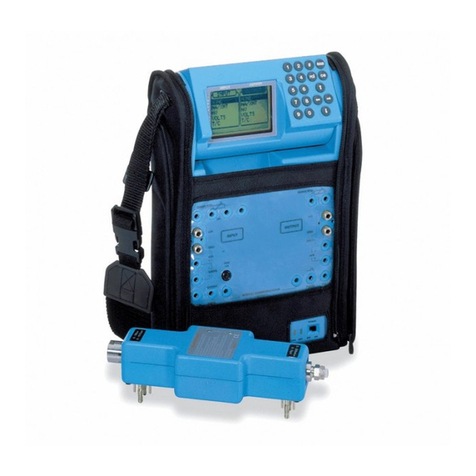
GE
GE Multilin EPM 7000 User manual

GE
GE Druck DPI 832 User manual

GE
GE EVT-Pro User manual

GE
GE Multilin MM300 User manual