GE RTT User manual

GE Consumer & Industrial
Multilin
RELAY TEST TOOL
Instruction Manual
GE Multilin
215 Anderson Avenue, Markham, Ontario
Canada L6E 1B3
Tel: (905) 294-6222 Fax: (905) 201-2098
Internet: http://www.GEmultilin.com
ISO9001:2000
G
E
M
U
L
T
I
L
I
N
R
E
G
I
S
T
E
R
E
D
GE Multilin's Quality Management
System is registered to ISO9001:2000
QMI # 005094
*1665-0003-CJ*
Manual P/N:1601-9021-A1
Manual Order Code: GEK-113388
Copyright © 2007 GE Multilin

These instructions do not purport to cover all details or variations in equipment nor provide
for every possible contingency to be met in connection with installation, operation, or
maintenance. Should further information be desired or should particular problems arise
which are not covered sufficiently for the purchaser’s purpose, the matter should be referred
to the General Electric Company.
To the extent required the products described herein meet applicable ANSI, IEEE, and NEMA
standards; but no such assurance is given with respect to local codes and ordinances
because they vary greatly.
© 2007 GE Multilin Incorporated. All rights reserved.
GE Multilin Relay Test Tool instruction manual.
Relay Test Tool and RTT, are registered trademarks of GE Multilin Inc.
The contents of this manual are the property of GE Multilin Inc. This documentation is
furnished on license and may not be reproduced in whole or in part without the permission
of GE Multilin. The content of this manual is for informational use only and is subject to
change without notice.
Part numbers contained in this manual are subject to change without notice, and should
therefore be verified by GE Multilin before ordering.
Part number: 1601-9021-A1 (July 2007)

TABLE OF CONTENTS
DISTRIBUTED DIGITAL FAULT RECORDER – INSTRUCTION MANUAL TOC–I
Table of Contents
1: GETTING STARTED ORDERING ........................................................................................................................................... 1
ORDERING THE RTT ............................................................................................................ 1
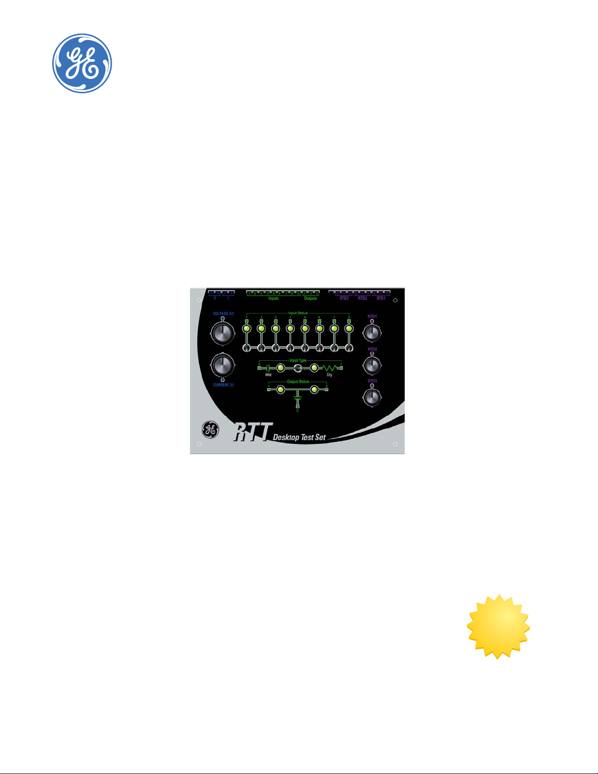
ABOUT YOUR NEW RTT UNIT ...................................................................................................... 2
CAUTIONS AND WARNINGS ............................................................................................... 2
CHECK THE CONTENTS OF THE BOX ................................................................................ 2
USING THIS MANUAL .......................................................................................................... 2
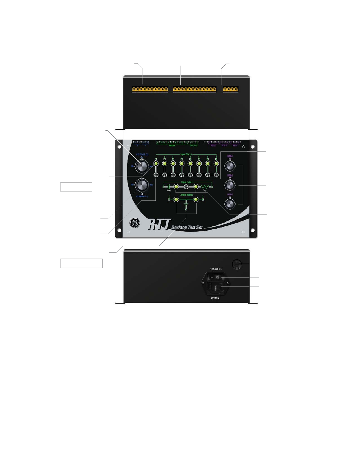
ABOUT THE RTT .................................................................................................................. 3
RTT UNIT SPECIFICATIONS ................................................................................................ 7
2: USING THE RTT ON SR
SERIES RELAYS
THE 469 MOTOR MANAGEMENT RELAY ................................................................................ 11
OVERVIEW ............................................................................................................................ 11
SR469 MOTOR MANAGEMENT RELAY TERMINAL LAYOUT .......................................... 12
SR469 MOTOR MANAGEMENT TERMINAL FUNCTIONS ................................................ 13
RTT TO SR469 WIRING DIAGRAM .................................................................................. 15
INTERFACING TO THE RTT THROUGH THE ENERVISTA 469 SETUP PROGRAM .......... 16
THE SR750/760 FEEDER MANAGEMENT RELAY ................................................................. 19
OVERVIEW ............................................................................................................................ 19
SR750/760 FEEDER MANAGEMENT RELAY TERMINAL LAYOUT ................................. 20
SR750/760 FEEDER MANAGEMENT RELAY TERMINAL FUNCTIONS .......................... 21
RTT TO SR750/760 WIRING DIAGRAM ........................................................................ 23
INTERFACING TO THE RTT THROUGH THE ENERVISTA 750/760 SETUP PROGRAM 24
THE SR489 GENERATOR MANAGEMENT RELAY ................................................................. 27
OVERVIEW ............................................................................................................................ 27
SR489 GENERATOR MANAGEMENT RELAY TERMINAL LAYOUT .................................. 28
SR489 GENERATOR MANAGEMENT RELAY TERMINAL FUNCTIONS ............................ 29
RTT TO SR489 WIRING DIAGRAM .................................................................................. 31
INTERFACING TO THE RTT THROUGH THE ENERVISTA 489 SETUP PROGRAM .......... 32
THE SR745 TRANSFORMER MANAGEMENT RELAY ........................................................... 35
OVERVIEW ............................................................................................................................ 35
SR745 TRANSFORMER MANAGEMENT RELAY TERMINAL LAYOUT .............................. 36
SR745 TRANSFORMER MANAGEMENT RELAY TERMINAL FUNCTIONS ....................... 37
RTT TO SR745 WIRING DIAGRAM .................................................................................. 39
INTERFACING TO THE RTT THROUGH THE ENERVISTA 745 SETUP PROGRAM .......... 40
THE SR735/737 FEEDER PROTECTION RELAY ..................................................................... 43
OVERVIEW ............................................................................................................................ 43
SR735/737 FEEDER PROTECTION RELAY TERMINAL FUNCTIONS ............................. 44
RTT TO SR735/737 WIRING DIAGRAM ........................................................................ 45
INTERFACING TO THE RTT THROUGH THE ENERVISTA 735/737 SETUP PROGRAM 46
3: USING THE RTT ON UR
SERIES RELAYS
CONFIGURATION OPTIONS ......................................................................................................... 47
OVERVIEW ............................................................................................................................ 47
UR SERIES RELAYS REAR TERMINAL LAYOUT ................................................................. 48
UR SERIES RELAYS CT/VT MODULE - TERMINAL FUNCTIONS .................................... 49
UR SERIES RELAYS TRANSDUCER & DIGITAL I/O MODULES
- TERMINAL FUNCTIONS ............................................................................................ 50
RTT TO UR RELAY WIRING DIAGRAM ............................................................................. 55
INTERFACING TO THE RTT THROUGH THE ENERVISTA UR SETUP PROGRAM ............ 56

TOC–II DISTRIBUTED DIGITAL FAULT RECORDER – INSTRUCTION MANUAL
TABLE OF CONTENTS
4: MOTOR MANAGEMENT
& METERING
THE 369 MOTOR MANAGEMENT RELAY .................................................................................61
OVERVIEW ............................................................................................................................ 61
369 MOTOR MANAGEMENT RELAY TERMINAL LAYOUT ................................................ 62
RTT TO 369 RELAY WIRING DIAGRAM ........................................................................... 63
INTERFACING TO THE RTT THROUGH THE ENVERVISTA 369 SETUP PROGRAM ........ 64
THE 239 MOTOR MANAGEMENT RELAY .................................................................................67
OVERVIEW ............................................................................................................................ 67
239 MOTOR MANAGEMENT RELAY TERMINAL LAYOUT ................................................ 68
239 MOTOR MANAGEMENT RELAY TERMINAL FUNCTIONS ......................................... 68
RTT TO 239 RELAY WIRING DIAGRAM ........................................................................... 69
INTERFACING TO THE RTT THROUGH THE ENVERVISTA 239 SETUP PROGRAM ........ 70
THE 269/269 PLUS MOTOR MANAGEMENT RELAY ........................................................... 72
OVERVIEW ............................................................................................................................ 72
269/269 PLUS MOTOR MANAGEMENT RELAY TERMINAL LAYOUT ............................ 73
RTT TO 269 WIRING DIAGRAM ....................................................................................... 75
INTERFACING TO THE RTT THROUGH THE 269PC PROGRAM ..................................... 76
THE PQM AND PQMII POWER QUALITY METERING SYSTEMS ...................................... 79
OVERVIEW ............................................................................................................................ 79
PQM/PQMII POWER QUALITY METERING SYSTEMS TERMINAL LAYOUT .................. 79
PQM/PQMII POWER QUALITY METERING SYSTEMS TERMINAL FUNCTIONS ........... 80
RTT TO PQM/PQMII RELAY WIRING DIAGRAM ........................................................... 81
INTERFACING TO THE RTT THROUGH THE ENVERVISTA PQM SETUP PROGRAM ...... 82
5: F650 FEEDER/BAY
PROTECTION RELAY
THE F650 FEEDER/BAY PROTECTION RELAY ........................................................................85
OVERVIEW ............................................................................................................................ 85
F650 FEEDER/BAY PROTECTION RELAY TERMINAL LAYOUT ........................................ 86
RTT TO F650 RELAY WIRING DIAGRAM ......................................................................... 87
INTERFACING TO THE RTT THROUGH THE ENERVISTA F650 SETUP PROGRAM ....... 88

RTT DESKTOP TEST SET– INSTRUCTION MANUAL 1
RTT Desktop Test Set
Chapter 1: Getting Started
GE Consumer & Industrial
Multilin
Getting Started
1.1 Ordering
1.1.1 Ordering the RTT
Select the basic model and the desired features from the selection guide below:
Table 1–1: Ordering Codes
RTT **
RTT-Cable

2RTT DESKTOP TEST SET– INSTRUCTION MANUAL
ABOUT YOUR NEW RTT UNIT CHAPTER 1: GETTING STARTED
1.2 About Your New RTT Unit
1.2.1 Cautions and Warnings
Before attempting to install or use the RTT unit, it is important that all DANGER and
CAUTION indicators in this manual are reviewed in order to prevent personal injury,
equipment damage and/or downtime. The above icons are used to indicate dangers,
cautions and notes.
The standard note icon emphasizes a specific point or indicates minor problems that may
occur if instructions are not properly followed.
The caution icon indicates that there may be possible damage to equipment or data if
instructions are not properly followed.
The danger icon provides users with a warning about the possibility of serious or fatal
injury to themselves or others.
1.2.2 Check the Contents of the Box
When you open the RTT box, you should find:
• one RTT unit
•onepowercord
• one RTT-to-product connecting cable
• manual
Note If there is any noticeable physical damage, or if any of the contents of the box are missing,
please contact GE Multilin immediately.
1.2.3 Using this Manual
This manual is designed with the assumption that you may or may not know about the
principles of RTT usage. If you know little about RTT usage, please read carefully what is
written below, bearing in mind that GE Multilin is available to fully support your questions
about any aspect of the product.
If this is not the case, simply ignore those sections of the manual with which you are
familiar.
The manual is structured to guide you through the entire installation and configuration
process, from opening the box, to:
• physically connecting the associated relays
• setting up the associated relays for use with the RTT
CAUTION NOTE

CHAPTER 1: GETTING STARTED ABOUT YOUR NEW RTT UNIT
RTT DESKTOP TEST SET– INSTRUCTION MANUAL 3
• creating RTT outputs for each type of relay
• viewing information about your relays based on inputs from your RTT.
Any actions you have to undertake during any part of the installation and configuration
processes, are indicated in the manual as follows:
ZOpen the box.
This makes it easier to separate what you must physically do, from the surrounding
product and process descriptions and explanations.
1.2.4 About the RTT
The RTT is a device that allows simple testing of electronic relays, by essentially simulating
input conditions to the relay in question.
It includes a single phase supply, where both volts and amperes are adjustable via rotary
knobs. It also includes eight circuits to drive the contact inputs of modern relays, as well as
2 contact outputs both monitored via LEDs. The RTT also has 3 channels of RTD resistance
simulators.
The features of the RTT allow you to test several functions of the relay, such as overcurrent,
overvoltage, directional units using the single phase source in a very easy and convenient
way. The main application is rough testing of relays in the laboratory or the field. It may
also be used for technicians and crew training purposes in a very cost effective way.
The unit is self powered from the mains and is able to work either at 50 or 60 Hz and all
common voltage ranges, 110, 120, 230, 240 Vac. When it is used with a modern
multimeter, it allows precise testing of relays and meters based on the comparison
principle.
The equipment may be used with all modern digital relays that have low burden in their
current and voltage inputs as well as low consumption digital inputs.

4RTT DESKTOP TEST SET– INSTRUCTION MANUAL
ABOUT YOUR NEW RTT UNIT CHAPTER 1: GETTING STARTED
The figure below shows the RTT box and describes all its features..
FIGURE 1–1: RTT Details
* In order to prevent accidental movement of the Wet/Dry toggle switch, the switch comes
with a locking feature: you must pull it upward in order to toggle the RTT between "Wet"
and "Dry" input.
Voltage/Current
Output terminals
Digital Input/Output
Terminals
RTD Terminals
Voltage Adjusting Knob
• clockwise to increase
• counter clockwise to
decrease
Digital Input
Status Indicators
LED ON: CLOSE
LED OFF: OPEN
Current Adjusting Knob
• clockwise to increase
• counter clockwise
to decrease
Digital Input
Toggle Switches
Output Status Indicators
LED ON: ENERGIZED
LED OFF: DE-ENERGIZED
RTD Resistance
Adjusting Knobs
• clockwise to increase
• counter clockwise to
decrease
Wet/Dry Indicator
Input Type
Wet/Dry Toggle Switch
*
Fuse
Power Line Inlet
Top View
Back View
Front View
Power Switch

CHAPTER 1: GETTING STARTED ABOUT YOUR NEW RTT UNIT
RTT DESKTOP TEST SET– INSTRUCTION MANUAL 5
The figure below shows the cable provided with the RTT. This cable is used to connect to
all relays, although for some, it may have to be slightly modified. See the appropriate
chapter for details.
FIGURE 1–2: Connecting the Cable to the RTT Unit

6RTT DESKTOP TEST SET– INSTRUCTION MANUAL
ABOUT YOUR NEW RTT UNIT CHAPTER 1: GETTING STARTED
The figure below shows the wire labels (see figure 1-2, above), that correspond to the RTT
terminals..
RTD1 +
18 AWG
RTD1 -
RTD1 C
RTD2 +
RTD2 -
RTD2 C
RTD3 +
RTD3 -
RTD3 C
SPARE
Output C
18 AWG
Output 2
Output 1
Input C
Input 8
Input 7
Input 6
Input 5
Input 4
Input 3
Input 2
Input 1
Current I+10 AWG
Current I-
Voltage V+18 AWG
Voltage V-

CHAPTER 1: GETTING STARTED ABOUT YOUR NEW RTT UNIT
RTT DESKTOP TEST SET– INSTRUCTION MANUAL 7
1.2.5 RTT Unit Specifications
LED INDICATOR LIGHTS
A single green LED is provided for each digital input from and output to the relay under
test.
CONTROL POWER
RANGE:
Nominal AC Voltage:.....................................100 V to 240 V AC at 50/60 Hz
Min/Max AC Voltage:.....................................85 V / 250 V AC at 47 to 63 Hz, 70 mA max.
AT 120 VAC INPUT
Nominal: ............................................................3 VA
Maximum:..........................................................5 VA
AT 240 VAC INPUT
Nominal: ............................................................6 VA
Maximum:..........................................................14 VA
FUSE1
5 × 20mm, 80 mA, 250V
Time-lag fuse
Manufacturer and part number: ...........LITTELFUSE: 218.080
CURRENT OUTPUT
AT 120 VAC INPUT
Range: ................................................................0 to 3 A AC at 0.08 ΩCT Relay Burden
AT 240 VAC INPUT
Range: ................................................................0 to 6 A AC at 0.08 ΩCT Relay Burden
Tolerance: ..........................................................±10%
VOLTAGE OUTPUT
AT 120 VAC INPUT
Range: ................................................................0 to 40.0 VAC
AT 240 VAC INPUT
Range:..................................................................0 to 80.0 VAC
Tolerance: .........................................................±10%
RTD OUTPUT (NON-LINEAR)
For Wire Type:..................................................3 wires
For Sensor Type: .............................................100 Ωplatinum, 100 Ωnickel, 120 Ωnickel
Resistance: ........................................................110 to 160 Ω
Tolerance: ..........................................................±5%
DIGITAL INPUTS
DRY:
Contact Resistance: ......................................< 10 mΩ
Insulation Resistance: ..................................> 1000 MΩ
WET:
DC Voltage:........................................................23.4 VDC @ 200mA
Tolerance: ..........................................................±5%
1. Fuse Replacement:
- Disconnect Power Supply and remove fuse from its holder.
- Replace with a 80 mA, 250 V, time-lag fuse. Use ONLY fuses indicated in above specifications.

8RTT DESKTOP TEST SET– INSTRUCTION MANUAL
ABOUT YOUR NEW RTT UNIT CHAPTER 1: GETTING STARTED
AMBIENT TEMPERATURE
Operating Range: ...........................................5ºC to 40ºC
Storage Range:................................................-20ºC to 70ºC
PHYSICAL
Size: 7.5" L × 5.75" W × 3.25" D / 187 mm L × 145 mm W × 81 mm D
Weight: 4.95 lb / 2.26 Kg
INTERNATIONAL STANDARDS COMPLIANT
When used with advanced protection relays such as the GE Multilin Universal Relay family, the
RTT complies with most international standards requirements for test and measuring
equipment:
EN61326:1997
EN/IEC 61010-1:2001
cULus 61010-1
ENVIRONMENTAL
Indoor use
Altitude:...............................................................Up to 2000 m
Recommended operating
ambient temperature (Tmra).............5°C to 40°C
Relative Humidity: ..........................................0 to 90%, non-condensing
Mains supply voltage fluctuations: ........up to 10% of nominal voltage
Installation Category:...................................II
Max. Branch circuit:.......................................20 A
Pollution Degree: ............................................2
RTT TYPE TESTS
EMC TEST STANDARD CRITERIA
Electrostatic Discharge: Air and
Direct
IEC 60255-22-2 /
IEC 10004-2
4 KV Contact and 8 KV
Air
Electrical Fast Transient/Burst
Immunity-Capacitive Clamp
IEC 60255-22-4 /
IEC 10004-4
2 KV, 5 KHz (Power), 1
KV 2.5 KHz (I/O)
Surge Immunity IEC 60255-22-5 /
IEC 10004-5
0.5 KV diff, 1 KV com
Voltage Dip; 2. Voltage
Interruption
IEC 61000-4-11 0.5 cycle each polarity
& 100%
RF Immunity 80 to 1000 MHz IEC 60255-22-3 /
IEC 61004-3 & ETP 5.2
10 V/m
Conducted RF Immunity
150 KHz to 80 MHz
IEC 60255-22-6 /
IEC 10004-6
10 Vrms Am 80% mod
Power Frequency Magnetic Field
Immunity
IEC 61000-4-8 30 A/m
Pulse Magnetic Field Immunity EN/IEC 61000-4-9:1994,
2001
1000 A/m
Conducted Emissions
EN61000-6-4:2001
IEC 60255-25 / CISPR22 Class A

CHAPTER 1: GETTING STARTED ABOUT YOUR NEW RTT UNIT
RTT DESKTOP TEST SET– INSTRUCTION MANUAL 9
Radiated Emissions
EN61000-6-4:2001
IEC 60255-25 / CISPR22 Class A & B
ENVIRONMENTAL TESTS
Relative Humidity Cyclic EN/IEC 60068-2-30:2005 55°C, 93% RH, 6 days
Cold Temperature IEC 60068-2-1 -40°C, 16 hours
Dry Heat Temperature IEC 60068-2-2 +85°C, 16 hours
Sinusoidal Vibration IEC 60255-21:1996, 1988;
IEEE C37.1
10 Hz - 150 Hz, 1G,
Z-axis
SAFETY TESTS
Dielectric Strength Per EN/IEC 61010-1 Up to 1700 VAC, 1 min
ISM-Safety EN/IEC 61010-1
ISM-Safety UL/ULC 61010-1
EMC TEST STANDARD CRITERIA

10 RTT DESKTOP TEST SET– INSTRUCTION MANUAL
ABOUT YOUR NEW RTT UNIT CHAPTER 1: GETTING STARTED

RTT DESKTOP TEST SET– INSTRUCTION MANUAL 11
RTT Desktop Test Set
Chapter 2: Using the RTT on SR
Series Relays
GE Consumer & Industrial
Multilin
Using the RTT on SR S eries Relays
2.1 The 469 Motor Management Relay
2.1.1 Overview
The SR469 Relay has 3-phase current inputs with CT burden less than 0.2VA at rated load, 3
differential current inputs with the same CT burden and 3-phase voltage inputs with
greater than 500KOHM VT burden. There are also 9 digital inputs designed for Dry contact
connection only, and 6 Form-C output relays. The SR469 Relay monitors up to 12 RTD
inputs, each RTD being field programmable as a 3-wire type of 100 Platinum, 100 Nickel
and 120 Nickel.
All features of RTT can be applied to the SR469 Relay. Although there are no unused
terminals on the RTT product cable, a modification to the cable is required in order to fit it
to the SR469 terminals.
Modification of the Product Cable
For the wires related to contact inputs and RTDs (18 in total), cut the lugs off the wire, strip
wire to make them fit to the SR469 terminals.
The lugs to be cut are: R1+, R1-, R1C, R2+, R2-, R2C, R3+, R3-, R3C, DIC, DI8, DI7, DI6, DI5,
DI4, DI3, DI2 and DI1.

12 RTT DESKTOP TEST SET– INSTRUCTION MANUAL
THE 469 MOTOR MANAGEMENT RELAY CHAPTER 2: USING THE RTT ON SR SERIES RELAYS
2.1.2 SR469 Motor Management Relay Terminal Layout
FIGURE 2–1: SR469 Terminal Layout
806
77
9
A7.DW
G

CHAPTER 2: USING THE RTT ON SR SERIES RELAYS THE 469 MOTOR MANAGEMENT RELAY
RTT DESKTOP TEST SET– INSTRUCTION MANUAL 13
2.1.3 SR469 Motor Management Terminal Functions
FIGURE 2–2: SR469 Terminal Functions Schematic

14 RTT DESKTOP TEST SET– INSTRUCTION MANUAL
THE 469 MOTOR MANAGEMENT RELAY CHAPTER 2: USING THE RTT ON SR SERIES RELAYS

CHAPTER 2: USING THE RTT ON SR SERIES RELAYS THE 469 MOTOR MANAGEMENT RELAY
RTT DESKTOP TEST SET– INSTRUCTION MANUAL 15
2.1.4 RTT to SR469 Wiring Diagram
1. Ensure that Wet/Dry Input Type switch is set to DRY before applying power to the RTT
unit. The SR469 Relay accepts only DRY contact connections from the RTT.
2. Ensure that current and voltage knobs are turned fully counter-clockwise before
applying power to the RTT unit.
Note *Trip and Alarm Common terminals (F1 and F4) must be hardwired together.
Table 2–1: SR469 with RTT Set to Dry
RTDs
RTD 3 + A6 ------------------------- RTD3 +
RTD 3 - A8 ------------------------- RTD3 -
RTD 3 COM A7 ------------------------- RTD3 C
RTD 2 + A5 ------------------------- RTD2 +
RTD 2 - A3 ------------------------- RTD2 -
RTD 2 COM A4 ------------------------- RTD2 C
RTD 1 + A1 ------------------------- RTD1 +
RTD 1 - A3 ------------------------- RTD1 -
RTD 1 COM A2 ------------------------- RTD1 C
SPARE
Contact
Outputs*
AUX 3 COMMON F4 --------------
RTT
TRIP COMMON F1 ------------------------- OUTPUT C
AUX 3 NO E5 ------------------------- OUTPUT 2
TRIP NO E2 ------------------------- OUTPUT 1
Contact
Inputs
Switch Common D23 ------------------------- INPUT C
Access C1 ------------------------- INPUT 8
Assignable #4 D22 ------------------------- INPUT 7
Assignable #3 D21 ------------------------- INPUT 6
Assignable #2 D20 ------------------------- INPUT 5
Assignable #1 D19 ------------------------- INPUT 4
Remote Reset D18 ------------------------- INPUT 3
Emergency Restart D17 ------------------------- INPUT 2
Starter Status D16 ------------------------- INPUT 1
CTs Ia + G6 ------------------------- I+
Ia COM H6 ------------------------- I-
VTs VA G2 ------------------------- V+
Vn G1 ------------------------- V-

16 RTT DESKTOP TEST SET– INSTRUCTION MANUAL
THE 469 MOTOR MANAGEMENT RELAY CHAPTER 2: USING THE RTT ON SR SERIES RELAYS
2.1.5 Interfacing to the RTT through the EnerVista 469 Setup Program
The following information describes how to configure the SR469 relays and how to monitor
voltage and current inputs using the 469 Setup Software and the RTT.
2.1.5.1 Current
ZSetup: Enter the Phase CT Primary, then press Save.
FIGURE 2–3: Current Setup
ZMetering: The current values measuerd by the relay can be viewed
on the following screen in real-time.
FIGURE 2–4: Current Metering
Table of contents
Other GE Test Equipment manuals

GE
GE MicroVersaTrip TVTS1 User manual

GE
GE Multilin EPM 7000 User manual

GE
GE Druck ADTS 505 User manual

GE
GE Druck ADTS 405 R/F Mk2 User manual

GE
GE Druck UPS-III User manual

GE
GE SpotChecker User manual

GE
GE EVT-Pro 2.0 User manual

GE
GE Druck DPI 610 User manual

GE
GE Druck DPI 610 User manual

GE
GE Druck DPI612 User manual
Popular Test Equipment manuals by other brands

PRESIDIUM
PRESIDIUM Diamond Mate PDMT Series User handbook

Walter
Walter SURFOX owner's manual

Static Solutions
Static Solutions OHM-STAT CT-8700 Owners manual and operation guide

Horiba Scientific
Horiba Scientific LAQUA 6581S-10C instruction manual

Fluke
Fluke 5520A Service Service manual

Ritmix
Ritmix RAT-730 Operation manual