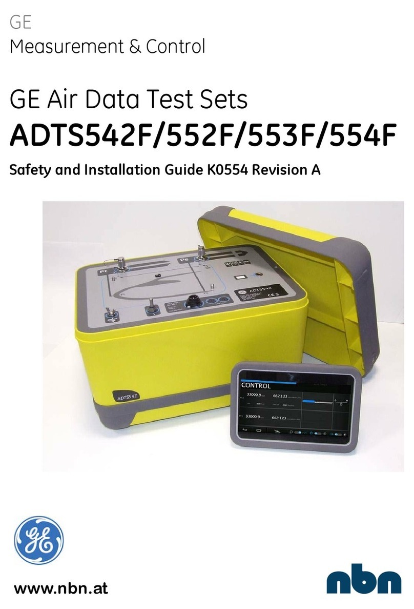
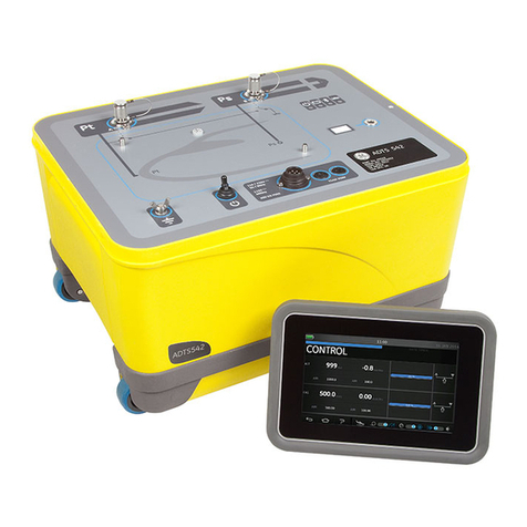
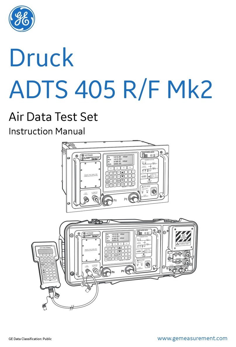
GE Druck ADTS 542F Setup guide

www.gemeasurement.com
GE Data Classification: Public
Druck
ADTS 542F/552F/553F/554F
Air Data Test Set
Safety and Installation Guide
English 1 - 20
Dansk 21 - 40
Deutsch 41 - 60
Español 61 - 80
Français 81 - 100
Italiano 101 - 120
Lietuvių121 - 140
Norsk 141 - 160
Português 161 - 180
Türkçe 181 - 200
Русский 201 - 220
Иކ 221 - 240
মୁ 241 - 260


© 2014 General Electric Company – All rights reserved. ADTS Safety and Installation Guide-English | 3
1. Introduction
This manual is applicable to ADTS542F/552F/553F and 554F, referred to as ADTS, and
provides safety and installation information for the Air Data Test Set, compatible with the
requirements of first line operation.
A touchscreen (ADTS Touch) is used to control all required functions. The ADTS Touch can be
positioned on the ADTS or used as a hand held mobile unit via a cable or Bluetooth® wireless
technology. This allows a person to complete the entire test program remotely while
conveniently seated in the aircraft. An ADTS Touch-ER option can be purchased for robust
wireless communications in a large body aircraft. The ADTS Touch can be powered when
positioned on the ADTS, or using a cable connection to the ADTS or battery powered.
The manufacturer has designed this equipment to be safe when operated using the
procedures detailed in this manual.
For details of calibration requirements for the ADTS, refer to User Manual K0553.
For details of available manufacturer specified parts, refer to the current revision of the
product data sheet.
Service/maintenance and repair will be carried out at GE authorized service centers.

Chapter 1. Introduction
4 | ADTS Safety and Installation Guide-English © 2014 General Electric Company – All rights reserved.
1.1 Markings and Symbols
For the list of GE approved service centers, go to:
www.gemeasurement.com
1.2 Intended Use
Test and calibration of aircraft aeronautical pressure instruments located indoor in a hanger
or calibration laboratory or outdoor (non-continuously) on a runway, refer to User Manual
K0553 for further information.
If the equipment is used in a manner not specified by this document and K0553 the
protection provided by the equipment may be impaired.
1.3 Safety
Examine all equipment to be used, paying particular attention to electrical leads and
connectors and pneumatic pipes and connectors. DO NOT use any equipment that is known
to be or suspected to be damaged or faulty.
Symbol Description
This equipment meets the requirements of all relevant European safety directives.
The equipment carries the CE mark.
This symbol, on the equipment, indicates that the user should read the user
manual.
This symbol, on the equipment, indicates a warning and that the user should refer
to the user manual.
This symbol warns the user of the danger of electric shock.
Do not dispose of this product as household waste. Use an approved organization
that collects and/or recycles waste electrical and electronic equipment. For more
information, contact our customer service department, or your local government
office.
The Bluetooth® wireless technology word mark and logos are registered
trademarks owned by Bluetooth SIG, Inc. and any use of such marks by GE is under
license. Other trademarks and trade names are those of their respective owners.
WARNING This equipment is not rated for use in potentially explosive
atmospheres. Using this equipment in a potentially explosive atmosphere
could lead to serious injury or death.

Power Supply
© 2014 General Electric Company – All rights reserved. ADTS Safety and Installation Guide-English | 5
1.4 Power Supply
1.5 Power Supply Connection
Do not apply electrical power outside the values stated.
Make sure that the power supply is off before connecting the power cable.
The ADTS must be connected to the correct electrical power supply as stated, adjacent to the
power connector.
1.6 Fuses
The two High Breaking Capacity fuses (8) (see Figure 3.1), located in the holders and mounted
on the front panel, protect the unit. The fuses are connected in the live and neutral supply
circuit and are rated at: T5AH 250V.
1.7 Replacing a Fuse
1. Disconnect the electrical power supply.
2. Unscrew the fuse holder cap from the front panel and remove the fuse.
3. Fit a new fuse of the correct size and rating into the fuse holder cap.
4. Secure the fuse holder cap in the front panel.
Single phase 110/230 Vac, 50/60Hz
115 Vac, 400Hz
200 VA Max - ADTS542F/ADTS552F
300 VA Max - ADTS553F/ADTS554F
RISK OF ELECTRIC SHOCK There is a risk of electric shock/
electrocution if there is not a protective earth in place. The ADTS must, at
all times, be connected to the supply protective earth/ground.
The power supply cable and connector must be correctly rated for the
power supply. Only use power cables supplied by GE specifically for the
ADTS.
European Color US Color Function
Brown Black Live
Blue White Neutral
Green/Yellow Green Protective Earth (Ground)

Chapter 1. Introduction
6 | ADTS Safety and Installation Guide-English © 2014 General Electric Company – All rights reserved.

© 2014 General Electric Company – All rights reserved. ADTS Safety and Installation Guide-English | 7
2. ADTS Touch
The ADTS Touch is used to control all required functions. The ADTS Touch can be positioned
on the ADTS or used as a hand held mobile unit via a cable or Bluetooth® wireless technology.
The ADTS Touch will have power applied when:
• Positioned (docked) (1) on a powered-on ADTS.
• Using an umbilical cable connected to a powered-on ADTS.
• Powered from its own battery pack.
• Powered from a universal power supply unit
Figure 2-1: ADTS Touch Docking Connector
The ADTS Touch is equipped with an On/Off switch (2) and USB connectors for connection to
a PC or mass storage device (3).
Figure 2-2: Touch On/Off Switch and USB Connectors
1
32

Chapter 2. ADTS Touch
8 | ADTS Safety and Installation Guide-English © 2014 General Electric Company – All rights reserved.
Connector (4) allows connection between the base unit and the ADTS Touch using a 5 metre
or 18 metre umbilical cable.
Note: Only use cables that have been supplied by or purchased from GE.
Figure 2-3: ADTS Touch Umbilical Cable Connector
The ADTS Touch can contain one Lithium-ion battery which is housed in the battery
compartment of the ADTS Touch.
2.1 Replacing the Battery
Figure 2-4: ADTS Touch Battery Compartment
Note: Only use batteries that have been supplied by or purchased from GE.
Prior to replacing the battery, switch the ADTS Touch off. If the ADTS Touch is connected to
the umbilical cable or Docking connector, disconnect prior to removing the battery cover
plate.
4
55

Battery Care and Maintenance
© 2014 General Electric Company – All rights reserved. ADTS Safety and Installation Guide-English | 9
1. Unscrew the two thumbscrews (5) of the battery compartment cover plate and
remove the cover plate.
2. Use the tab attached to the battery to slide the battery out of the battery
compartment.
3. Fit a new or re-charged battery into the battery compartment, observing the keyed
orientation.
Note: The battery does not necessarily need to be new or re-charged. The ADTS
Touch will function safely and correctly with a flat battery when the umbilical
cable or dock charging supply is connected.
4. Refit the battery compartment cover plate and tighten the two thumbscrews (5). The
cover must be fitted correctly to maintain protection afforded.
2.2 Battery Care and Maintenance
The battery unit contains a Lithium-ion battery which requires no user maintenance. If
shipping an ADTS Touch and/or battery unit please contact your local service center
beforehand for shipping requirements. Battery must be removed from the ADTS Touch during
transportation. Prolonged exposure to temperature extremes may significantly reduce
battery lifetime. For maximum lifetime, avoid prolonged periods where the battery is exposed
to temperatures outside the range -30°C to +45°C.
The recommended storage temperature range is 5°C to 21°C (41°F to 98.8°F).
The battery is removable. The manufacturer makes the following safety recommendations.
The user should not:
• Short circuit the battery.
• Immerse the battery in any liquid.
• Disassemble or deform the battery.
• Expose to, or dispose of the battery in a fire.
• Subject the battery to excessive physical shock or vibration outside the specified
limits for the ADTS.
• Use a battery that appears to have suffered abuse.
• Charge with an unspecified charger or specified charger that has been modified. This
can cause breakdown of the battery or swelling and rupturing.
• Use a battery in an appliance or purpose for which it was not intended.
The battery unit is sealed for life, so leakage of electrolyte is not expected. If leakage of
electrolyte from the battery is observed, stop using the battery immediately and avoid
contact with the electrolyte. If skin or clothes come into contact with the electrolyte, wash
CAUTION When the battery compartment cover plate is removed and
the ADTS touch is tilted with the battery compartment facing downwards,
the battery can fall out of the ADTS touch causing damage to the battery.
Chapter 2. ADTS Touch
10 | ADTS Safety and Installation Guide-English © 2014 General Electric Company – All rights reserved.
immediately with soap and water. If electrolyte comes into contact with the eyes, wash the
eyes thoroughly with water and consult a doctor immediately.
The ADTS5xxF, ADTS Touch and ADTS Touch-ER contain a Lithium-ion coin cell. This coin cell
is not user replaceable. Installation and replacement shall only be performed by trained
personnel.
Always dispose of batteries safely and in accordance with local instructions.
2.3 Battery Charging
The battery in the ADTS Touch can be charged using one of the following methods:
• By placing the ADTS Touch onto a powered ADTS.
• By connecting the ADTS Touch connector (4) (see Figure 2-3) to the ADTS using the
umbilical cable.
• By using the AATOUCH-5 optional accessory desktop charger. The battery must be
removed from ADTS Touch when it is charged by the AATOUCH-5 desktop charger.
• Using a universal power supply unit connected to the ADTS Touch using an adapter:
Figure 2-5: Universal Power Supply Unit and Adapter
The ADTS Touch universal power supply and the desktop charger are both rated for indoor
use only.

Power-Up Test (see Figure 3.1)
© 2014 General Electric Company – All rights reserved. ADTS Safety and Installation Guide-English | 11
3. ADTS5xxF
Figure 3-1: ADTS542F Front Panel (See Figure 4-1 for other variants)
3.1 Power-Up Test (see Figure 3.1)
1. Fit “Pitot” (Pt) (1) and “Static” (Ps) (2) port blanks.
2. Ensure that the test set is connected to an external power supply and the supply is
switched on.
3. Use the On/Standby Switch (3) on the front of the test set to switch the test set on.
The test set performs a self test, resulting in a test set status indication (4a) “Pass” or
“Fault”.
1
3
6
24
57
8

Chapter 3. ADTS5xxF
12 | ADTS Safety and Installation Guide-English © 2014 General Electric Company – All rights reserved.
The test set status indications are as follows:
Figure 3-2: Test Set Status Indications
If the self test fails, or for any other reason the test set is considered to be
unserviceable, contact GE and return the test set to the GE or GE approved service
center.
4. To disconnect power to the test set, either:
Test Set Status Indications (4):
4a
Power on and self test:
- Off (Power Off)
- Standby (Yellow)
- Self test in Progress (flashing Green)
- Pass/Ready (Green)
- Fault (Red)
4b
Battery pack status (if fitted - ADTS542F only):
- For LED indications, see User Manual K0553 “ADTS542F Battery Pack”
Note: Battery pack is currently not a purchasable option.
4c
Bluetooth® wireless technology connection status:
- Wireless connection present (Blue)
- Wired connection and Bluetooth® option enabled (Flashing blue)
- Fast flash - enabled and visible for pairing (available for 5 minutes after power-up)*
- Slow blink - enabled but not visible for pairing*
- Bluetooth® option disabled (Wireless LED off)
- Initialization fault (Red) *
* Only applicable to base unit software variant DK0467
Note: The “fast flash” state also occurs when switching the ON/standby switch from standby
to ON. If the Bluetooth® link drops during use then “fast flash” will resume. This occasionally
requires the unit to be returned to standby mode before the link can be re-established.
4d
Aircraft status:
- When the ADTS is controlling the aircraft and it is “off ground”, the LED will be Yellow.
- When the ADTS is controlling the aircraft to “going to ground”, the LED will flash Yellow.
- When the ADTS has made the aircraft “safe at ground”, the LED is Green.
- In standby-mode, this LED will be off.
WARNING The On/Standby Switch (3) on the front of the test set is not
a disconnecting device.
4a 4b 4c 4d

External Functional Earth/Ground Terminal
© 2014 General Electric Company – All rights reserved. ADTS Safety and Installation Guide-English | 13
a. Remove the power cable (5) from the front of the test set, or
b. Remove the power cable from the wall socket. The wall socket connection
must remain accessible.
3.2 External Functional Earth/Ground Terminal
An external earth/ground connection stud (6) is available as a functional earth on the front
panel providing a connection/bonding point for other equipment to be connected to the
same earth/ground connection as the test set (This is not a protective earth/ground
connection).
3.3 Pneumatic Connections
No external pneumatic pressures or vacuums are required as the ADTS contains internal
pressure and vacuum pumps.
Hoses (available as orderable accessories on the datasheet) are used for connection to the
“Pitot” (Pt) (1) and “Static” (Ps) (2) output ports of the ADTS.
The “Pitot” (Pt) and “Static” (Ps) outputs can then be connected to the corresponding Pitot
and Static connectors on the aircraft or aeronautical instruments.
The maximum Pt and Ps output pressure is 2 bar absolute.
The following table details the possible connector specifications:
Mating female parts are available from GE.
Name Specification
G1/8 Pipe Thread ISO 228 - G 1/8 B
AN3 3/8 - 24 UNJF - 3A Thread
AN4 7/16 - 20 UNJF - 3A Thread
AN6 9/16 - 18 UNJF - 3A Thread

Chapter 3. ADTS5xxF
14 | ADTS Safety and Installation Guide-English © 2014 General Electric Company – All rights reserved.
3.4 Cleaning
The following materials are approved cleaning agents:
Note: Equivalent alternatives may be used for listed items.
1. Clean the external surfaces of the unit using lint-free cloth and a soft brush. Remove
stubborn dirt using a damp cloth and mild detergent and allow to dry.
2. Clean the electrical connector using a soft brush. Remove stubborn dirt using a damp
cloth and mild detergent and allow to dry.
CAUTION Do not use solvents to clean this equipment.
Material Specification
Lint-free cloth Commercially available
Damp cloth -
Mild detergent Commercially available
Soft brush Commercially available

Operating Environment
© 2014 General Electric Company – All rights reserved. ADTS Safety and Installation Guide-English | 15
4. Specification
4.1 Operating Environment
WARNING This equipment is not rated for use in potentially explosive
atmospheres.
Storage temperatures ADTS542F: -20°C to 70°C (-4° to 158°F)
ADTS552F )
ADTS553F ) -20°C to 70°C (-4° to 158°F)
ADTS554F )
Operating temperatures/
environment
ADTS542F: -5°C to 50°C (32° to 122°F)
ADTS552F )
ADTS553F ) -5°C to 50°C (32° to 122°F)
ADTS554F )
Operating humidity: 5% to 95% RH (condensing)
Indoor & Outdoor (non-continuously) use
ADTS Touch universal
power supply
Operating temperature: 10°C to 50°C (50° to 122°F)
Operating humidity: 5% to 95% RH (non-condensing)
Power supply Universal input Mains Power Supply.
Class 1 equipment requiring a protective earth connection.
TXAH 250V HRC Time-delay (T) 250Va.c. rated fuses (X = amp rating
of fuse).
Overvoltage category II, Pollution degree 2
The supplied mains/PSU cable protective earth/ground conductor
must be connected to the power supply protective earth/ground
system.
Electrical safety EN 61010-1, UL 61010-1, CSA 22.2, No. 61010-1 and IEC 61010-1
Operating altitude Maximum 7500ft (2300 metres)
Ingress protection ADTS542/552/553/554 IP33, ADTS Touch IP65 (EN60529)

Chapter 4. Specification
16 | ADTS Safety and Installation Guide-English © 2014 General Electric Company – All rights reserved.
4.2 Dimensions
Figure 4-1: ADTS 5xxF Variants
WARNING The ADTS can be moved by use of the handle and wheels. if
the ADTS is to be lifted, it must be lifted by at least two people.
ADTS5xxF Weight ADTS542F: 14kg (31lb) (without battery, estimated
as 20kg (44lb) with battery)
ADTS552F: 22kg (48.5lb)
ADTS553F: 23.5kg (52lb)
ADTS554F: 24.5kg (54lb)
Height 300mm
Depth ADTS542F: 320mm (front to rear)
ADTS55xF: 425mm (front to rear)
Width ADTS542F: 420mm (left to right)
ADTS55xF: 525mm (left to right)
ADTS Touch Weight 1kg (2.2lb)
1.4kg (3lb) with battery
Height 58mm
Depth 154mm
Width 224mm
ADTS542F
ADTS553F ADTS554F
ADTS552F

Product Labeling
© 2014 General Electric Company – All rights reserved. ADTS Safety and Installation Guide-English | 17
4.3 Product Labeling
The product label for the base unit can be found in the bottom right hand corner of the front
panel. The product label for the ADTS Touch can be found on the rear of the ADTS Touch.
Labeling information consists of:
1. Company logo and product name.
2. Part number
3. Serial number
4. Date of manufacture (DOM).
5. Name and address of manufacturer.
Figure 4-2: Product Labels

Chapter 4. Specification
18 | ADTS Safety and Installation Guide-English © 2014 General Electric Company – All rights reserved.


Imagination at work
© 2014 General Electric Company – All rights reserved.
Specifications are subject to change without notice. GE is a registered trademark of General Electric Company. Other company or
product names mentioned in this document may be trademarks or registered trademarks of their respective companies, which are not
affiliated with GE.
K0554 Revision C | English
Office Locations
Services and Support Locations
Australia France Germany
Springfield Central
Phone: 1300 171 502
Email: [email protected]
Toulouse
Phone: +33 562 888 250
Email: [email protected]
Frankfurt
Phone: +49 (0) 69-22222-973
Email: [email protected]
India Italy Japan
Bangalore
Phone: 1-800-301-62632
Email: [email protected]
Milan
Phone: +39 02 36 04 28 42
Email: [email protected]
Chuo-ku
Tel: 03-6890-4538
Email: [email protected]
Netherlands Russia UK
Hoevelaken
Phone: +31 334678950
Email: [email protected]
Moscow
Phone: +7 495 739 6811
Email: [email protected]
Leicester
Phone: +44 (0) 116 2317233
Email: [email protected]
USA
Boston
Phone: 1–800-833-9438
Email: [email protected]
Tech Support Brazil China
Global
Email: [email protected]
Campinas
Phone: +55 11 3958 0098
Email: [email protected]
Changzhou
Phone: +86 (0) 519-83051779-3
Email: [email protected]
France India Japan
Toulouse
Phone: +33 562 888 250
Email: [email protected]
Pune
Phone: +91-2135-620421 to 425
Email: [email protected]
Niigata
Phone: +81 257 45 5509
Email: [email protected]
UAE UK USA
Abu Dhabi
Phone: +971 2 4079381
Email: [email protected]
Leicester
Phone: +44 (0) 116 2317674
Email: [email protected]
Billerica
Phone: 1-800-833-9438
Email: [email protected]
This manual suits for next models
3
Table of contents
Languages:
Other GE Test Equipment manuals

GE
GE PK-2 User manual

GE
GE Druck DPI 880 User manual

GE
GE FAT User manual

GE
GE Druck TRX-II User manual

GE
GE Druck DPI 832 User manual

GE
GE Druck PC6-IDOS User manual

GE
GE Druck DPI611 Operating and maintenance instructions

GE
GE Druck ADTS 2 Series Use and care manual

GE
GE ADTS552F Setup guide

GE
GE Druck DPI 610 User manual