GE K0341 User manual

GE
Sensing
Druck UPS-III-IS
Intrinsically Safe Loop Calibrator
User manual - K0341
II2GExibIICT4
Druck UPS-III-IS
Loop Calibrator
mA
mA(24V) COM
V

Approved Service Agents
For the list of service centres visit our web site:
www.gesensing.com
Symbols
This equipment meets the requirements
of all relevant European safety
directives. The equipment carries the
CE mark.
This symbol, on the instrument,
indicates that the user should refer to
the user manual.
Do not dispose of this product as
household waste. Use an approved
organisation that collects and/or
recycles waste electrical and electronic
equipment. For more information:
Contact us at www.gesensing.com

i K0341 Issue No. 2
The IECEx certificate for this equipment can be reviewed at the
following web site:
www.iecex.com

K0341 Issue No. 2 ii
A full copy of the ATEX certificate for this equipment can be
supplied, contact us at the following web site:
www.gesensing.com

iii K0341 Issue No. 2

K0341 Issue No. 2 iv

1 K0341 Issue No. 2
UPS-III Intrinsically Safe Loop Calibrator
Introduction
The Druck
UPS-III Intrinsically Safe Loop Calibrator
can supply
power (
source mode
) and produce readings (
measure
mode
) to perform field calibrations on 2-wire devices.
The set-up menu enables the user to “source” or
“measure” in either voltage or current and to perform
continuity tests.
These instructions detail the requirements
and operation of the UPS III Intrinsically Safe Loop Calibrator
in a hazardous area. Read the whole publication before
starting.
Installation Requirements in Hazardous Areas
Marking details
Serial number/year of manufacture
1180
Baseefa06ATEX0224X
IECEx BAS 06.0053X
Ex ib IIC T4 (-10°C <Ta <+40°C)
Druck, LE6 0FH, UK (manufacturer)
Requirements and Conditions
Refer to the supply and input/output parameter table.
Batteries
WARNING: Only replace batteries in a safe area
Only use the battery type listed below.
Requirements
Installing should be carried out by qualified plant installation
technicians in compliance with the latest issue of EN 60079-14.
Special Conditions for Use
This loop calibrator may be used in zones 1 and 2 for industries
with any gas group.
• Maximum component temperature class T4 (135°C).
• Only use 4 x LR6 (size AA), Duracell PROCELL, Duracell
PLUS, ENERGIZER ULTIMATE or GP SUPERALKALINE LR6.
Loop Calibrator Casing
• Avoid impact sparking when installing in a hazardous area.
• Provide additional protection for calibrators that may be
damaged in service.
2

K0341 Issue No. 2 2
Declaration Requirements
The Intrinsically Safe UPS-III is designed and manufactured to meet the
essential health and safety requirements not covered by EC Type
Examination Certificate
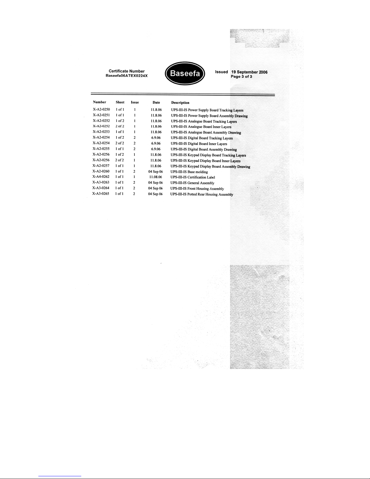
Baseefa06
ATEX0224 when installed as detailed
above.
This intrinsically safe loop calibrator is designed and manufactured to
protect against other hazards as defined in paragraph 1.2.7 of Annex II of
the ATEX Directive 94/9/EC.
Specifications
Accuracies
1 year for 17°C to 27°C outside these limits
...................................................................... 0.003%/°C(0.0015%/F°)
Reference.................................................. 22°C ±5°C/RH45%±15%
*R max 650
Ω
at 20 mA lsd least significant digits
** R-measure >1M
Ω
rdg reading
*** Audio + visual
†maximum 24V, typically 21V
Hart® communications................menu selectable 220
Ω
loop resistor
Operating Temperature..................... -10°C to 40°C (14°F to 104°F)
Storage Temperature.............................-20°C to 70°C (-4°F to 158°F)
This loop calibrator meets the essential protection
requirements of the relevant EEC directives.
Electrical Power Supply
Only use 4 x LR6 (size AA), Duracell PROCELL, Duracell PLUS,
ENERGIZER ULTIMATE or GP SUPERALKALINE LR6.
Physical
Dimensions....................................90 x 140 x 42 mm(3.5” x 5.5” x 1.7”)
Weight (nominal)........................................................460 grams (16.2 oz.)
Terminals ................................................................................ 4 mm sockets
Case ................................................................................ High impact ABS
Environmental............................................................................................ IP40
Relative Humidity........................................................................... 0 to 90%
Mode Range Resolution Accuracy
Source 2 wire† 0 to 24 mA 0.001 0.015% rdg + 2 lsd
Source mA 0 to 24 mA*0.001 0.015% rdg + 2 lsd
Measure mA 0 to 24 mA 0.001 0.015% rdg + 2 lsd
Measure V 0 to 50V** 0.01 0.015% rdg + 4 lsd
Continuity <100Ω*** -0.5mA

3 K0341 Issue No. 2
Table 1
Guide to supply and input/output
No. Parameter and conditions
&
Current measurement between mA and COM with
external 24V. This mode of operation inserts the apparatus
in the current loop by breaking into the circuit and
connecting mA (positive) and COM (negative) into the
circuit.
Current measurement between mA (24V) and mA with
internal 24V. Terminal mA(24V) provides the source of
power to supply remote sensor.
Special condition for safe use - remote sensor MUST be
isolated from all other sources of power.
Voltage measurement between V and COM
Continuity measurement between V and COM
Special condition for safe use - remote sensor MUST be
isolated from all other sources of power.
Current generation between mA and COM with external
24V. This mode of operation inserts the apparatus in the
current loop by breaking into the circuit and connecting
mA (positive) and COM (negative) into the circuit.
Current generation between mA (24V) and mA with
internal 24V. Terminal mA (24V) provides the source of
power to supply the remote sensor.
Special condition for safe use - remote sensor MUST be
isolated from all other sources of power.
1
2
3
44
5
6
7

K0341 Issue No. 2 4
Table 2
Supply and input/output parameter
* Special condition for safe use
#220pF consists of 110pF @ 6.51 V max and 110pF @ 1.6V max.
Param. &
Ui30V 0* 50V 0* 30V 0*
Ii100mA 0* 100mA 0* 100mA 0*
Pi1W 0* 1W 0* 1W 0*
U06.51V 25.2V 6.51V 6.51V 6.51V 25.2V
I014mA 158mA 12mA 8mA 14mA 158mA
P022mW 0.995W 20mW 20mW 22mW 0.995W
Ci220pF# 220pF# 110pF 110pF 220pF# 220pF#
Li000000
C033nF 53nF 10nF 11µF 33nF 53nF
L01.5mH 500µH 1.5mH 100mH 1.5mH 500µH
1
2
3
44
5
6
7

5 K0341 Issue No. 2
OPERATION
Keys
The key switches the loop
calibrator on and off. Press and hold
for 2 seconds.
The key changes the measure or
source operating mode. Pressing the
keys makes menu selections,
sets numerical values and controls
step and ramp functions (up/down).
The select advanced
functions shown on the bottom of the display. When no key is
pressed for 10 minutes, the loop calibrator times out and
switches off. To disable this automatic time out, select
autpower down in the set-up menu.
MODE
F2
F1
SPAN CHECK
MODE
F2
F1

K0341 Issue No. 2 6
Operating Modes
Pressing
switches the instrument on and the display shows
the start-up sequence. Pressing , at this time, the display
shows the information screen:
Pressing , at this time, the display shows the set-up screen:
The calibrator can be used in two modes
measure
or
source
.
Measure mode
The display shows the measured value; depending on the
settings made in set-up and advanced settings:
When measuring current pressing enables linear or flow,
pressing enables mA or % (value of 4 to 20 mA or 0 to 20
mA).
When measuring voltage pressing changes the resolution
between 0.00V and 0.000V.
To measure continuity the displays shows an open or closed
switch symbol with an audible signal on switch closure.
F1
F1 Serial number
VERSION
CAL. DATE
HART
BATTERY
Information
F2
F2
Resolution adjust
F2
Contrast adjust
F2
Range 4-20 mA/0-20mA
F2
Source unit mA/%
F2
Hart® ON/OFF
F2
Aut power down ON/OFF
F2
Decimal .,/
F2
Access code menu
F2
Calibration menu
F2
F1
F2
F2

7 K0341 Issue No. 2
Connect the calibrator to the device to be tested:
and Measure mA
Press the mode
key and select
[Measure mA]. An
external power
supply supplies a
maximum of 30 V
for the loop. The
calibrator
measures the
current of the
loop.
Closed loop
current
measurement
from transmitter
test terminal
Measure mA with
24 V*
Press mode key and
select [Measure mA and
24V]. The calibrator
supplies 24 V
(maximum) for the loop,
maximum 24 mA.
*Special condition for safe use, see page 3.
Measure Volts
Press mode key and
select [Measure Volts],
measure range 50 V,
maximum impedance 1
Mohm.
1
+
-
Hazardous
area
Safety
barrier
Safe
area
Advanced %
+100.0%
+20.000
mA
mA
mA ( 24V ) COM
V
*
2
Hazardous
area
+
-
Safety
barrier
Safe
area
Advanced %
+100.0%
+20.000
mA
mA
mA( 24V )COM
V
3
Advanced %
+100.0%
+24.000
mA
mA
mA(24V)COM
V
21V
4
Advanced %
+100.0%
mA
mA(2
4V )COM
V
+50.000 V

K0341 Issue No. 2 8
Continuity Test*
Press mode key and
select [Continuity Test].
Pressing switches
the audible signal on/off.
Source Mode
The display shows the source value in mA or % value of 4 to 20
mA or 0 to 20 mA, linear or flow depending on the settings
made in set-up and advanced settings.
*Special condition for safe use, see page 3.
Source mA
Press mode key and
select [Source mA].
Source mA with
24V*
Press mode key and
select [Source mA and
24V]. The calibrator
supplies loop power of:
24 V [maximum],
(typically 21V) and 24
mA.
*Special condition for
safe use, see page 3.
5
+20.000
mA
Step off
+100.0%
mA
mA(2
4V )COM
V
Rmax = 650 Ohms
6
+
-
Hazardous
area
Safety
barrier
Safe
area
Advanced %
+100.0%
mA
mA(24V)COM
V
+12.000 V
I/P
_+
7
Advanced %
+100.0%
mA
mA(24V)COM
V
+24.000
mA

9 K0341 Issue No. 2
Advanced Options in a Source mode
Press the key and select mA Source or mA Source & 24V.
Use and
(Enter) to select the function.
Press the key (Advanced) and the display shows:
Linear simulates linear transmitters.
Flow simulates flow transmitters.
Valve simulates valve control signals.
Use and
(Enter) to select the Advanced option:
Advanced
Note: Ramp function not available for valve selection.
Use
to quit.
The display returns to the selected source
mode with the advanced setting available.
Step 25% steps for linear and flow - fixed values for
valve.
Auto-step The same as step with a timed step interval.
Span Check Step between 4 (or 0) mA and 20 mA.
Ramp Automatic ramp between 4 (or 0) mA and 20 mA.
MODE
F1 Lin
Flow
Valve
Step
Auto-step
Span Check
Ramp
Time (M:SS)
Time (M:SS)
Adjust +1/ -1 second
F2
Mode mA source
mA source & 24V select Enter
Advanced
select
F2
select
F2
F2
F2

K0341 Issue No. 2 10
Operation of Advanced Options
Press the key to switch the advanced setting on and off:
e.g.
on or off
Press or to:
step the output up or down.
step the span check maximum or minimum
start the “ramp”.
Press then to start:
continuous auto-step.
or
continuous ramp cycle.
Hart® Application
This application allows mA measure and source modes to be
used through the Hart® communicator.
Advanced %
+100.0%
mA
mA(24
V)COM
V
+24.000
mA
Hart®
communicator
W
220W
menu selectable loop resistor

11 K0341 Issue No. 2
Maintenance
• Return the loop calibrator to an authorised ATEX repair
centre for any repairs, it cannot be repaired on-site.
• To keep the loop calibrator accurate a calibration check
should be carried out once per year.
Cleaning
• Clean the loop calibrator leather case with a moist, lint-
free cloth and weak detergent.

K0341 Issue No. 2 12
Battery Replacement
WARNING: ONLY REPLACE BATTERIES IN A SAFE AREA
Only use the battery type listed on page two.
Unscrew and remove the securing screw from the battery panel.
Replace the batteries, check the polarity of the batteries. Refit and
secure the battery panel.

13 K0341 Issue No. 2
Calibration Instructions
WARNING:
CALIBRATE UPS-III-IS LOOP CALIBRATORS IN A SAFE AREA.
General
The instrument is supplied by the manufacturer, complete
with calibration certificate(s). A calibration period of 12
months is recommended. The actual calibration interval
depends on instrument usage and the total measurement
uncertainty acceptable for the specified application.
The
UPS-III-IS
is a very precise measuring instrument and the test
equipment and conditions of test must be suitable for the type
of work. The calibration check and calibration adjustment
should be carried out in a controlled environment by a
calibration technician*.
The manufacturer offers a comprehensive and, if required,
UKAS accredited calibration service.
*
A calibration technician must have the necessary technical knowledge,
documentation, special test equipment and tools to carry out the calibration
work on this equipment.
Calibration Equipment
The following tables give the accuracy requirements for the
calibration equipment and the UPS-III-IS.
Calibration requires a stable temperature of 21° ±1°C (70° ±2°F).
UPS-III-IS measure mode
Table 3
mA measure
Applied
mA
Permitted UPS-III-IS
error (mA)
Calibrator error
(mA)
0 0.002 0
4 0.002 0.00014
12 0.002 0.00030
20 0.002 0.00046

K0341 Issue No. 2 14
Table 4
V measure
UPS-III-IS source mode
Table 5
mA source
Calibration Check
1.Connect the UPS-III-IS to the electrical calibrator. Switch on
the electrical calibrator and allow it to thermally stabilise.
2.Switch on the UPS-III-IS and allow the instrument to thermally
stabilise.
3.Set the UPS-III-IS to mA measure, adjust the electrical
calibrator to apply the first value in the table 3. Record the
reading of the UPS-III-IS.
4.Repeat step 3 for all the values in the table 3.
5.Compare the recorded values and the applied values if the
difference is greater than the permitted error, the instrument
requires a calibration adjustment.
6.Repeat this procedure for V measure (table 4) and mA source
(table 5).
Calibration Adjustment
1.Connect the UPS-III-IS to the electrical calibrator. Switch on
the electrical calibrator and allow it to thermally stabilise.
Applied V Permitted UPS-III-IS
error (mV)
Calibrator error
(mV)
0 0.004 0.00040
20 0.004 0.00014
40 0.005 0.00064
50 0.005 0.00070
Applied
mA
Permitted UPS-III-IS
error (mA)
Calibrator error
(mA)
0 0.002 0
4 0.002 0.00012
12 0.002 0.00011
20 0.002 0.00015
This manual suits for next models
1
Table of contents
Other GE Test Equipment manuals

GE
GE Druck DPI 880 User manual

GE
GE EVT-Pro 2.0 User manual

GE
GE DPI620G-IS User manual

GE
GE Druck PC6-IDOS User manual

GE
GE MicroVersaTrip TVTS1 User manual

GE
GE Multilin MM300 User manual

GE
GE Druck UPS-III User manual

GE
GE Druck DPI 620 User manual

GE
GE Druck ADTS 2 Series User manual

GE
GE EntelliGuard G User manual
Popular Test Equipment manuals by other brands

Vitalograph
Vitalograph Lung Monitor BT Smart Instructions for use

Hakko Electronics
Hakko Electronics FG-470 instruction manual

OWL
OWL VOLT-1 Operation guide

CharlesWater
CharlesWater 99090 Operation and maintenance

Advanced Power technologies
Advanced Power technologies ECLIPSE Application guide

Teledyne
Teledyne T3DSO3000 quick start guide