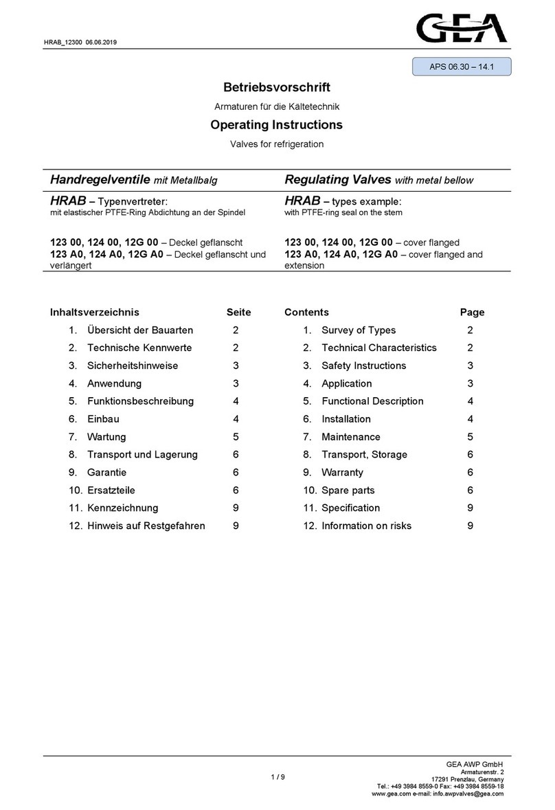
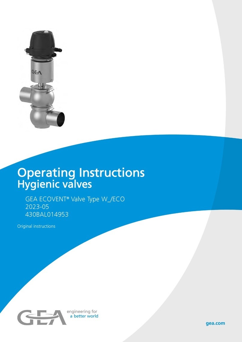
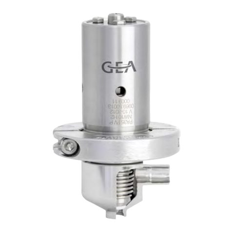
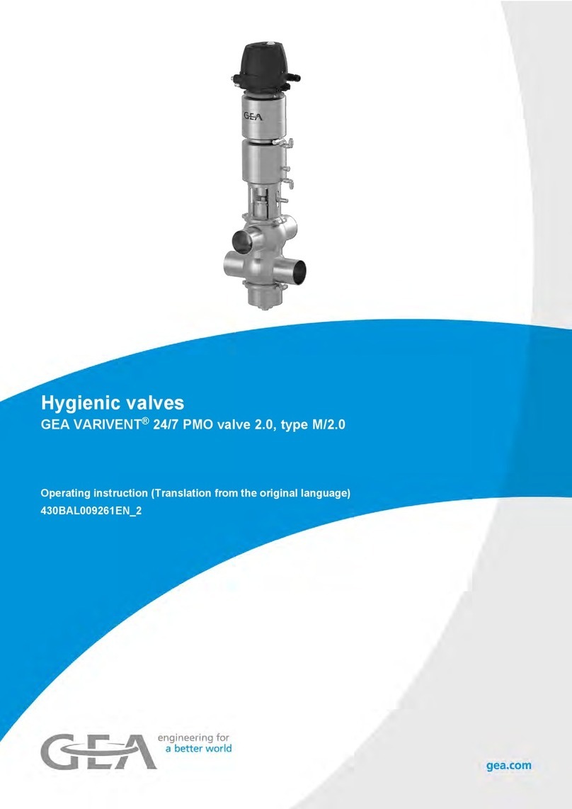
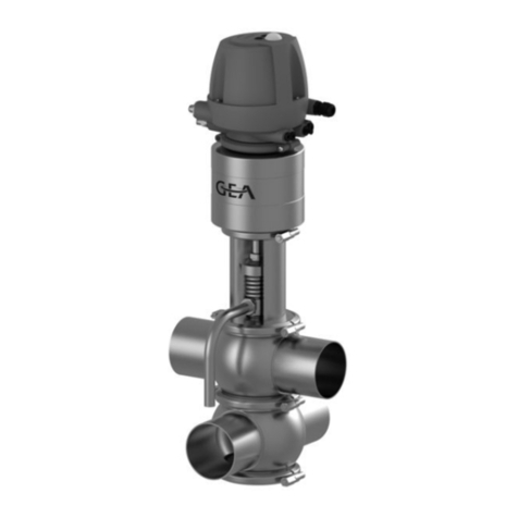
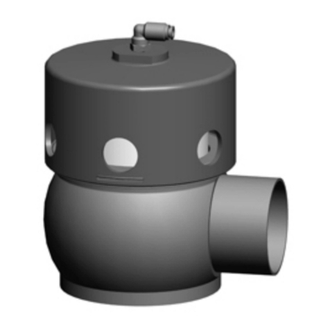
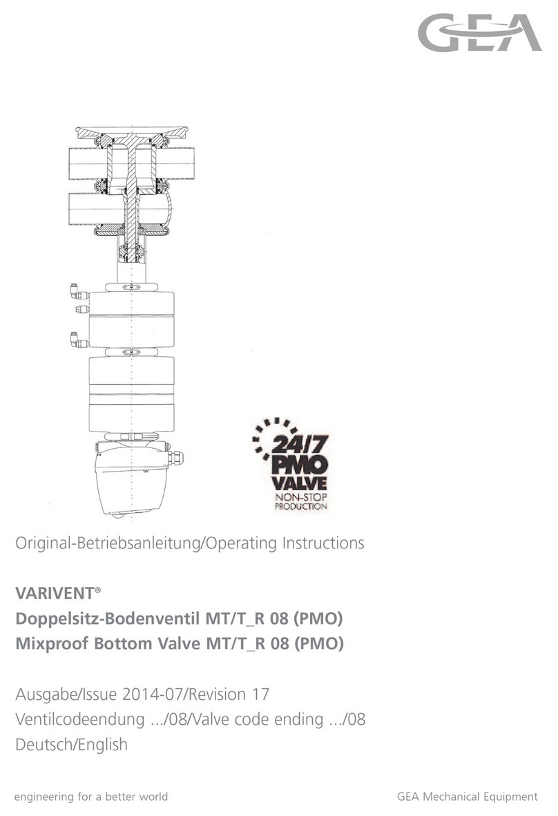
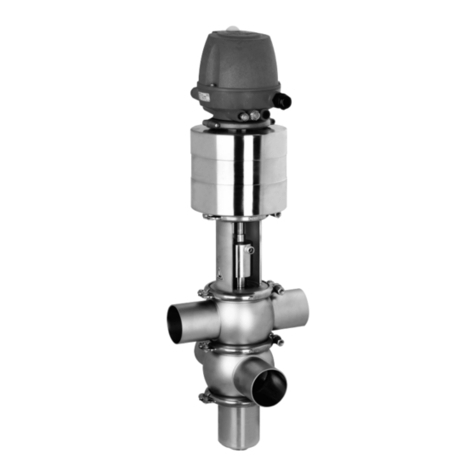
GEA ECOVENT N ECO Series User manual

Operating Instructions
Hygienic valves
GEA ECOVENT® Valve Type N_/ECO
2023-03
430BAL008482
Original instructions

Table of Contents
1 General
1.1 Information about the document 7
1.1.1 Purpose and structure of the document 7
1.1.2 Design elements 7
1.1.3 Reading obligation and storage 8
1.2 Manufacturer address 8
1.3 Customer service 8
1.4 Declarations of conformity 9
2 Safety
2.1 Intended use 13
2.1.1 Requirements for the operation 13
2.1.2 Pressure equipment directive 13
2.1.3 ATEX directive 13
2.1.4 Improper operating conditions 14
2.2 Modication 14
2.3 Structure of warning notices 14
2.3.1 Preceding warning notices 14
2.3.2 Integrated warning notices 14
2.3.3 Signal words 14
2.4 Personnel qualication 15
2.5 General safety instructions 15
2.5.1 General hazard 16
2.5.2 Mechanical hazard 16
2.5.3 Electrical hazard 16
2.5.4 Thermal hazard 16
2.6 Personal protective equipment 17
2.7 Safety devices 17
2.8 Residual hazards 17
2.9 Safety signs 19
2.10 Emergency measures 19
Table of Contents - 3 / 106

3 Description
3.1 Set-up and function 21
3.1.1 Design 21
3.1.2 Functional description 22
Spring-to-close actuator function (NC) 22
Spring-To-Open actuator function (NO) 22
Modifying the actuator closing direction 22
3.1.3 Signs 24
3.1.4 Protective devices 24
3.2 Technical data 25
3.2.1 Type plate 25
3.2.2 Technical data 25
3.2.3 Resistance of the sealing materials 28
3.2.4 Pipe ends - General table of measurements 29
3.2.5 Lubricants 30
4 Storage and transport
4.1 Scope of supply 31
4.2 Storage 31
4.3 Transport 32
5 Assembly and installation
5.1 Notes on installation 33
5.2 Control top 33
5.3 Install the valve with detachable pipe connection elements 33
5.4 Install valve with welding ends 33
5.5 Checking the pneumatic connection 35
5.5.1 Air requirement 35
5.5.2 Establishing hose connections 35
5.6 Electrical connection with T.VIS control top 37
6 Commissioning
6.1 Preparing commissioning 39
6.2 Restarting 40
7 Operation and control
7.1 Monitoring operation 41
7.2 Shutdown 41
8 Cleaning
8.1 General points 43
8.1.1 Cleaning process examples 43
8.1.2 Cleaning results 44
8.2 Passivation 44
4 / 106 - Table of Contents
0000000576 - 001 - EN-GB

9 Maintenance
9.1 Carrying out inspections 45
9.1.1 Checking seals that come into contact with the product 45
9.1.2 Checking the pneumatic connection 45
9.1.3 Checking the electrical connection 46
9.1.4 Checking the signs on the valve 46
9.2 Servicing intervals 46
9.3 List of tools 46
9.4 Prior to removal 48
9.5 Removing the valve 48
9.5.1 Removing the clamp connection between the housing and lantern
48
9.5.2 Removing the control top 54
9.5.3 Disconnecting the valve insert from the housing 54
9.5.4 Dismantling the valve insert into individual parts 55
9.5.5 Dismantling of the housing combination 61
9.6 Installing the valve 61
9.6.1 Tightening torques 61
9.6.2 Assembling the valve insert from individual parts 62
9.6.3 Assembly of the housing combination 69
9.6.4 Placing the valve insert in the housing 69
9.6.5 Mounting the control top 70
9.6.6 Mounting the clamp connection between the housing and lantern
70
9.6.7 Checking the function 75
9.7 Maintenance 76
9.7.1 Cleaning the valve 76
9.7.2 Replacing seals 78
Replacing the V-ring 78
Replacing more seals 80
9.7.3 Lubricating seals and threads 81
10 Faults
11 Decommissioning, dismantling and disposal
11.1 Decommissioning 85
11.2 Dismantling 85
11.3 Disposal 85
12 Spare parts
12.1 Order information 87
12.2 Spare parts lists 88
13 Annex
13.1 Dimensions sheet - Valve N_/ECO 99
13.2 Dimensions sheet - Actuator ECO-E 101
13.3 List of abbreviations 104
Table of Contents - 5 / 106

6 / 106 - Table of Contents
0000000576 - 001 - EN-GB

1 General
This chapter contains basic instructions for using the valve and explanations of illustra-
tion conventions. It also contains information about the design and structure.
The term valve in these Operating Instructions refers to GEA ECOVENT® Valve Type N_/
ECO.
1.1 Information about the document
1.1.1 Purpose and structure of the document
The objective of these Operating Instructions is to provide information on how to oper-
ate the valve. To achieve this, it is divided into several chapters which are oriented on
the various life phases of the valve. Compliance with the instructions will enhance the
valve's longevity and reliability, and reduce the likelihood of harm to individuals or dam-
age to property. The Operating Instructions also acts as the basis for creating operating
instructions.
1.1.2 Design elements
In this document, the following design elements are used as orientation aids.
General orientation aids
●Figure numbers
●Table numbers
●Chapter numbers
●Page numbers
●Headers and footers
●References
●Lists
Lists
Bullet points are shown in lists and do not prescribe a specic sequence.
●Bullet point
●Bullet point
•Sub-point
•Sub-point
●Bullet point
Numbered lists
In a sequence of actions, the order of the action steps is specied by a numbered list.
Partial results and the result of a sequence of actions are marked by arrows.
1. Action step one
2. Action step two
2.1 First sub-step two
2.2 Second sub-step two
®Partial result
3. Action step three
®Partial result
4. Action step four
ÞResult
1.1 Information about the document - 7 / 106

INFO
Info texts contain additional information about a description or action step.
1.1.3 Reading obligation and storage
Every person who works on or with the valve must have read these Operating Instruc-
tions. They must be available to these persons at all times.
1.2 Manufacturer address
GEA Tuchenhagen GmbH
Am Industriepark 2-10
Germany
21514 Büchen
1.3 Customer service
Phone: +49 4155 49-0
Fax: +49 4155 49-2035
www.gea.com
8 / 106 - 1.2 Manufacturer address
0000000576 - 001 - EN-GB

1.4 Declarations of conformity
1.4 Declarations of conformity - 9 / 106

Translated copy of the EU - Declaration of conformity in accordance with the
Pressure Equipment Directive 2006/42/EU
Manufacturer: GEA Tuchenhagen GmbH
Am Industriepark 2-10
21514 Büchen
We hereby declare that the machine named below
Designation: Valve with actuator
Type: ECOVENT®
on the basis of its design and construction, as well
as the version that we have put into circulation,
corresponds with the relevant fundamental health
and safety requirements of the following guide-
line:
Relevant EC directives: 2006/42/EC EC Machinery Directive
Applicable harmonized standards, in particular: EN ISO 12100: 2010
Remarks: ●This declaration will become invalid if any alter-
ations are made to the machine which have
not been agreed with us
●We also declare that the relevant technical
documentation for this machine has been pre-
pared in accordance with Annex VII, Part A,
and agree to submit the documentation on
justied request of national authorities on a
data carrier
Person authorised for compilation and handover
of technical documentation:
GEA Tuchenhagen GmbH
CE Documentation Ofcer
Am Industriepark 2-10
21514 Büchen, Germany
Büchen, 06 January 2021
Franz Bürmann
Managing Director
i.V. Matthias Südel
Head of Engineering
10 / 106 - 1.4 Declarations of conformity
0000000576 - 001 - EN-GB

1/1
UK- Declaration of Conformity by Supply of Machinery (Safety) Regulations 2008
Manufacturer:
GEA Tuchenhagen GmbH
Am Industriepark 2-10
21514 Büchen, Germany
Hereby, we declare that the machine designated in the following
Designation:
Valve with actuator
Type:
ECOVENT®
by virtue of its design and construction and in the versions placed on the market by us, complies with the essential health
and safety requirements of the following directive:
Relevant UK legislation:
Supply of Machinery (Safety) Regulations 2008
Applicable harmonized standards, in
particular:
EN ISO 12100: 2010
Safety of machinery - General principles for design
- Risk assessment and risk reduction
Remarks:
•In the event of a modification to the machine that was not agreed with us, this declaration loses its
validity
•Furthermore, we declare that the specific technical documentation for this machine has been drawn
up in accordance with Annex VII, Part A, and undertake to forward this documentation by means of
data medium upon justified request by the national authorities.
GEA Importer into UK:
GEA Mechanical Equipment UK Ltd
Westfalia House
Old Wolverton Road, Old Wolverton, Milton Keynes
MK12 5PY, United Kingdom
Person authorised for compilation and handover of technical
documentation:
Michael Kiely
GEA Mechanical Equipment UK Ltd
Westfalia House
Old Wolverton Road, Old Wolverton, Milton Keynes
MK12 5PY, United Kingdom
Büchen, 14 March 2023
________________________________ ________________________________
Franz Bürmann i.V. Matthias Südel
Managing Director Senior Director Engineering
1.4 Declarations of conformity - 11 / 106

12 / 106 - 1.4 Declarations of conformity
0000000576 - 001 - EN-GB

2 Safety
This chapter describes the minimum requirements for the intended use of the valve. It
forms the basis for safe operation of the valve.
2.1 Intended use
The valve is used for opening and closing pipeline sections.
Proper use of the valve also includes compliance with these Operating Instructions.
The medium should preferably ow in the opening direction of the valve disk to avoid
pipe hammers when the valve is opened or closed.
In a closed pipe system, hydraulic pressure build-up may occur when the valve switches
and result in seal damage.
INFO The manufacturer will not accept any liability for damage resulting from
any use of the valve which is not in accordance with the designated use of
the valve. The risk is borne solely by the operating company.
2.1.1 Requirements for the operation
The prerequisite for the reliable and safe operation of the valve is proper transportation
and storage as well as professional installation and assembly. Operating the unit within
the limits of its designated use also involves adhering to the operating, maintenance
and servicing instructions.
2.1.2 Pressure equipment directive
The valve is a piece of pressure equipment (without safety function) in the sense of the
pressure equipment directive 2014/68/EU: Classied according to Annex II in category
1.
According to the scope of directive 2014/34/EC, article 1, paragraph 2, f), the excep-
tion of the directive applies, due to conformity with the Machinery Directive
2006/42/EC.
The nominal diameters smaller than DN 25 are subject to article 4, paragraph 3 of the
Pressure Equipment Directive which species sound engineering practice.
Nominal diameters ≥ IPS 4“; DN 125 valid for the uid group II.
In the event of any deviations, GEA Tuchenhagen GmbH will supply a special Declara-
tion of Conformity.
2.1.3 ATEX directive
In areas with an explosive atmosphere, only valves suitable for use in such areas may be
used.
Refer to and observe the additional instruction manual “ATEX version valves”. For de-
tails regarding the marking of valves for potentially hazardous areas also refer to the
additional instruction manual “ATEX version valves”.
If these valves are used in areas with a potentially explosive atmosphere, it is mandatory
to comply with directive 2014/34/EC with respect to all ignition hazards.
2.1 Intended use - 13 / 106

2.1.4 Improper operating conditions
The operational reliability of the valve cannot be ensured under improper operating
conditions. Therefore avoid improper operating conditions.
Operating the valve is not permitted if
●Persons or objects are in the danger zone.
●Safety devices are not working or were removed.
●Malfunctions have been detected on the valve.
●Damage has been detected on the valve.
●Maintenance intervals have been exceeded.
2.2 Modication
Subsequent alterations of the valve are not permitted. Otherwise you will have to un-
dergo a new conformity process in accordance with the EC Machinery Directive on your
own.
In general, only genuine spare parts supplied by GEA Tuchenhagen GmbH should be
tted. This ensures the reliable and economical operation of the valve.
2.3 Structure of warning notices
Warning notices warn of hazards which can occur when certain actions are carried out.
The warning notices described below are used in this document. The extent of hazards
is classied in risk levels and can be recognised by the respective signal words.
2.3.1 Preceding warning notices
Preceding warning notices are used when there is a hazard during a sequence of ac-
tions. Warning notices are colour-highlighted and supplemented by a pictogram in the
event of possible personal injury.
Figure 2-1 - Structure of a preceding warning notice
2.3.2 Integrated warning notices
Integrated warning notices are used when there is a hazard involved in a single action
step.
Figure 2-2 - Structure of an integrated warning notice
2.3.3 Signal words
IMPORTANT
The signal word IMPORTANT indicates a hazard that could result in property damage if
not avoided.
14 / 106 - 2.2 Modication
0000000576 - 001 - EN-GB

CAUTION
The signal word CAUTION indicates a hazard with a low risk level which could result in
light to medium injuries if not avoided.
WARNING
The signal word WARNING indicates a hazard with a medium risk level which could re-
sult in death or severe injury if not avoided.
DANGER
The signal word DANGER indicates a hazard with a high risk level which will result in
death or serious injury if not avoided.
2.4 Personnel qualication
The following basic requirements must be fullled for all actions carried out on the
valve.
●These Operating Instructions have been read and understood.
●Safety tasks in and around the valve are regulated and assigned.
•Maintaining order
•Compliance with safety requirements
•Securing hazard zones
Additionally, the following groups of people must possess the personnel qualications
or skills listed below and be authorised by the operator to perform actions on the valve.
Operating staff
●Trained by the operating company, a qualied customer specialist or a GEA service
expert
Customer specialist
●Technical training
Trained customer specialist
●Technical training in a specic eld of expertise
●Training by GEA personnel or participation in training courses of the Büchen
GEA service expert
●Personnel from GEA Tuchenhagen, see
1.3 Customer service
Where necessary, reference is made to the respective group of individuals in these Op-
erating Instructions.
2.5 General safety instructions
The valve was built in accordance with the state of the art and recognised safety regu-
lations at the time of its launch. However, the safety measures stipulated by the opera-
tor and listed below must still be adhered to in order to ensure safety.
2.4 Personnel qualication - 15 / 106

2.5.1 General hazard
Source Consequences Measures
Faulty valve Injury and damage Check that the valve is fully
functional.
Non-compliance with these Op-
erating Instructions
Injury and damage Read and familiarise yourself
with these Operating Instruc-
tions.
Operating materials Injuries ●Wear personal protective
equipment.
●Avoid contact with operating
materials.
2.5.2 Mechanical hazard
Source Consequences Measures
Moving or rotating components ●Being drawn in or caught
●Entrapment
●Crushing
●Impact
●Remove jewellery.
●Tie hair back or wear a hair
net.
●Wear tight-tting clothing.
●Gravity
●Falling objects
●Impact
●Crushing
●Do not walk under suspen-
ded loads.
●Eliminate the stumbling haz-
ards.
2.5.3 Electrical hazard
Source Consequences Measures
Electromagnetic processes Implications for electronic medi-
cal implants
People with medical implants
must keep their distance.
Electrostatic processes ●Electric shock
●Fire
●Chemical reaction
●Avoid contact to compo-
nents.
●Check the voltage of compo-
nents.
●Wear personal protective
gear.
●Eliminate leaked ammable
substances.
2.5.4 Thermal hazard
Source Consequences Measures
Objects or materials at high or
low temperature
●Freezing
●Burns
●Scalding
●Wear personal protective
gear.
●Wait for adjustment to room
temperature.
16 / 106 - 2.5 General safety instructions
0000000576 - 001 - EN-GB

2.6 Personal protective equipment
To prevent possible personal injuries, the personal protection equipment must be worn.
In addition, GEA recommends keeping the requirements listed below.
●Locally applicable accident prevention regulations
●Instruction manual from the operator or employer
2.7 Safety devices
No safety devices are attached to this valve.
2.8 Residual hazards
Despite all the measures taken, the following residual hazards can lead to personal inju-
ries and property damage at any time.
●Improper use
●Material fatigue
●Failure of safety devices
Danger zones
Please observe the following notes:
9
391
43
C
C
A
●In the event of malfunctions, shut down the valve (disconnect from the power and
air supply) and secure it against being used.
●Before starting any maintenance, servicing or repair work, disconnect the valve from
the power supply and secure it against inadvertently being switched back on again.
●Only allow a qualied electrician to carry out any work on the electrical power sup-
ply.
●Check the electrical equipment of the valve at regular intervals. Immediately remedy
loose connections and molten cables.
●If work on live parts cannot be avoided, call in a second person, who can operate
the main switch in case of an emergency.
2.6 Personal protective equipment - 17 / 106

●Never reach into the lantern (9) or the valve housing (391) when the valve is switch-
ing. Fingers can be crushed or cut off.
●On a spring-closing valve there is danger of injury when the clamp connection (43) is
opened, as the released spring pretension will suddenly lift the actuator. Therefore,
release the spring tension before detaching the clamp connection (43) by supplying
the actuator (A) with compressed air.
●The housing sockets (391) have very sharp edges. When transporting and installing
the valve be sure to wear suitable protective gloves.
●On versions with proximity switch holder do not put your ngers in the slots (C).
Dangerous situations can be avoided by safety-conscious and proactive behaviour of
the personnel and by wearing personal protective equipment.
Danger Cause Measure
Danger to life Inadvertent switch-on of the valve Effectively disconnect all components,
effectively prevent switch-on.
Electric power Observe the following safety rules:
1.Isolate from the power supply.
2.Take appropriate measures to pre-
vent switch on.
3.Test absence of voltage.
4.Earthing and short-circuiting.
5.Cover or safeguard any adjacent
live parts.
Spring tension in the actuator Danger to life caused by the pressur-
ised spring in the actuator. Do not
open the actuator, rather return it to
GEA Tuchenhagen for proper disposal.
Risk of injury Danger presented by moving or sharp-
edged parts
The operator must exercise caution
and prudence.
For all work:
●Wear suitable work clothing.
●Never operate the machine if the
cover panels are not correctly t-
ted.
●Never open the cover panels dur-
ing the operation.
●Never reach into openings.
As a precautionary measure, wear per-
sonal protective equipment in the vi-
cinity of the valve:
●Protective gloves
●Safety shoes
Environmental dam-
age
Operating materials with properties
which are harmful to the environment
For all work:
●Collect lubricants in suitable col-
lecting vessels.
●Dispose of lubricants in accord-
ance with the pertinent regula-
tions.
18 / 106 - 2.8 Residual hazards
0000000576 - 001 - EN-GB

2.9 Safety signs
The safety symbols listed below are attached to the valve.
The position of the applicable safety symbols on the valve are shown in an overview,
see
3.1.3 Signs
.
Warning signs
General warning sign
Hazard for persons, conveyed by the additional sign.
Warning, risk of hand injuries
Hazard posed by closing mechanical components on the valve.
Warning, spring tension
Hazard posed by spring tension. Do not open the actuator.
General warning symbol
Hazard for persons as shown by additional symbols.
2.10 Emergency measures
In case of any emergencies on the valve, the operating regulations must be observed
and the following actions implemented.
Fire
●Call local specialists
●Use extinguishing agents as outlined in the operating regulations
●Exit the hazard zone
●Warn individuals that are endangered
Injuries
●Administer rst aid
●Call local emergency services
2.9 Safety signs - 19 / 106

20 / 106 - 2.10 Emergency measures
0000000576 - 001 - EN-GB
Table of contents
Other GEA Control Unit manuals

GEA
GEA VARIVENT K User manual

GEA
GEA VARIVENT T R User manual

GEA
GEA VARIVENT Series User manual

GEA
GEA SVA 455 Series User manual

GEA
GEA VARIVENT D Series User manual

GEA
GEA VARIVENT T R User manual

GEA
GEA VARIVENT T R Series User manual
GEA
GEA AVR Series User manual

GEA
GEA VARIVENT TSVN User manual

GEA
GEA T-smart 7 User manual

GEA
GEA DHV User manual

GEA
GEA VARIVENT X User manual

GEA
GEA VARIVENT T 09 User manual

GEA
GEA Aseptomag GD User manual

GEA
GEA SVAB User manual

GEA
GEA H A/T Series User manual

GEA
GEA VP8002 User manual

GEA
GEA VARIVENT DN 25 User manual

GEA
GEA VARIVENT Mixproof T R Series User manual

GEA
GEA Aseptomag AV User manual