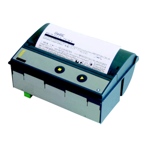
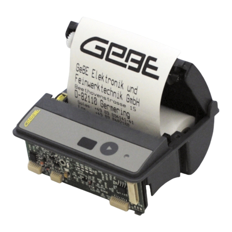
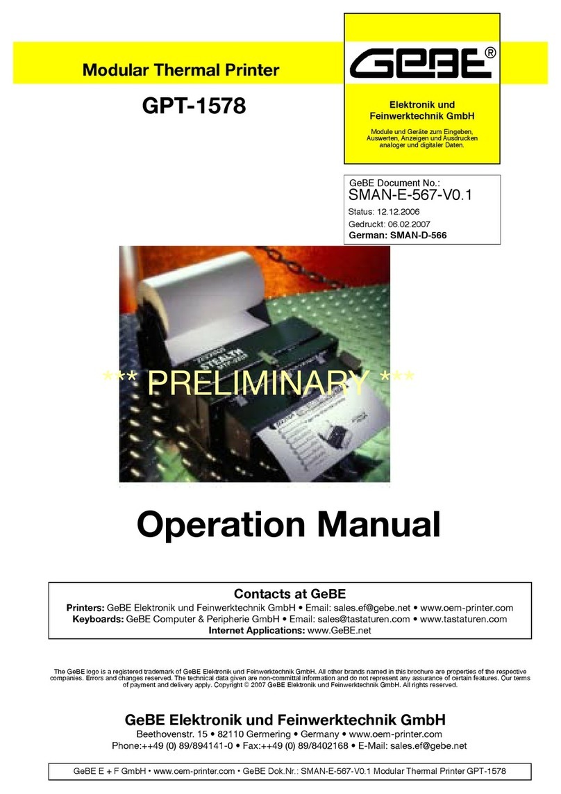
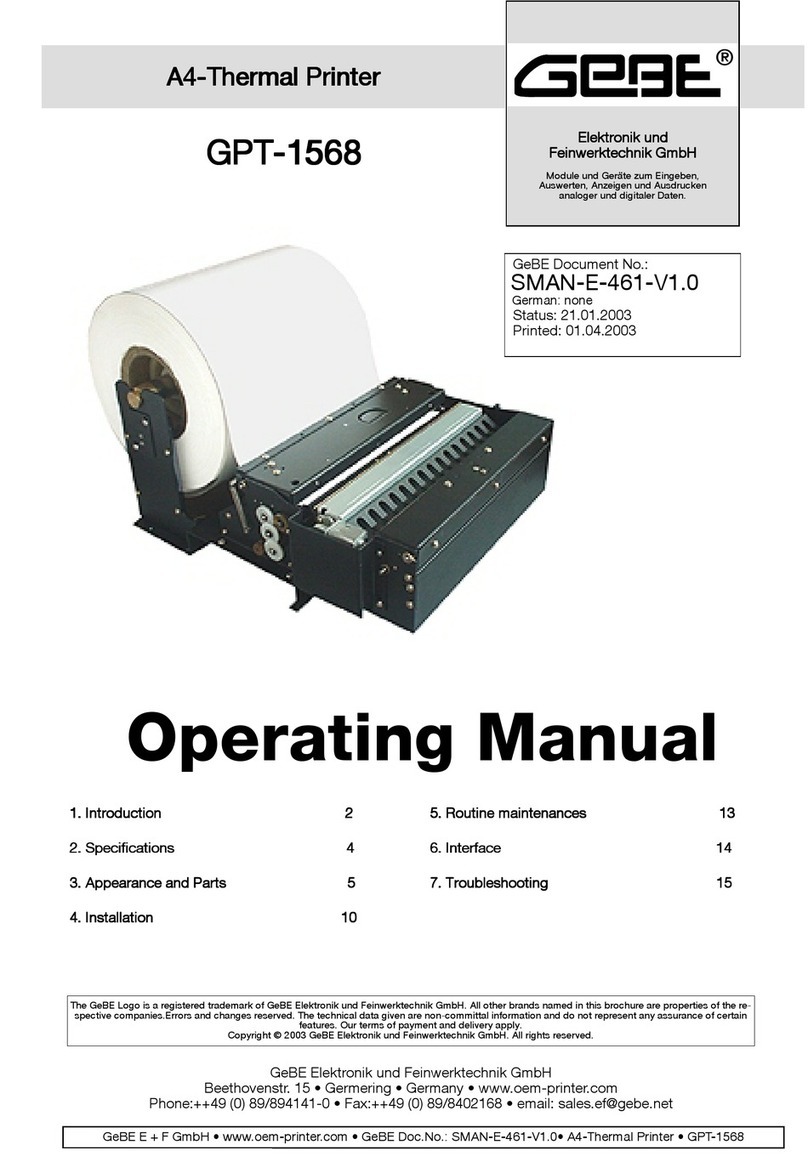
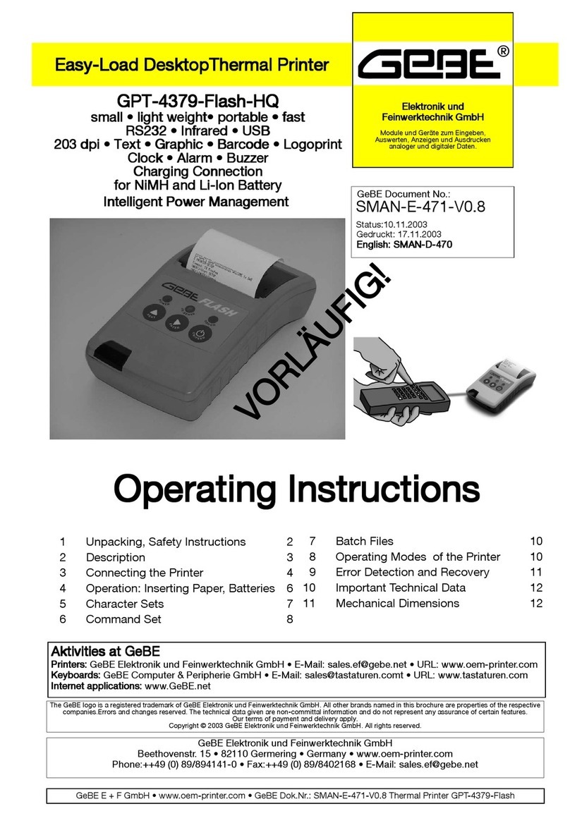
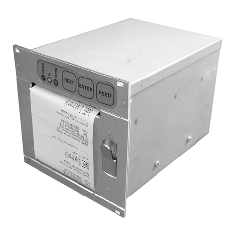
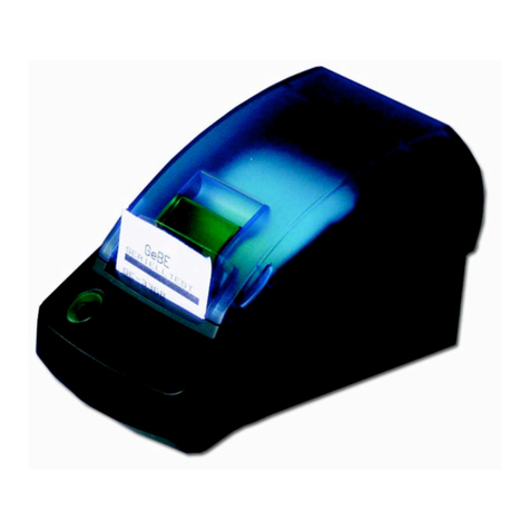
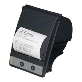
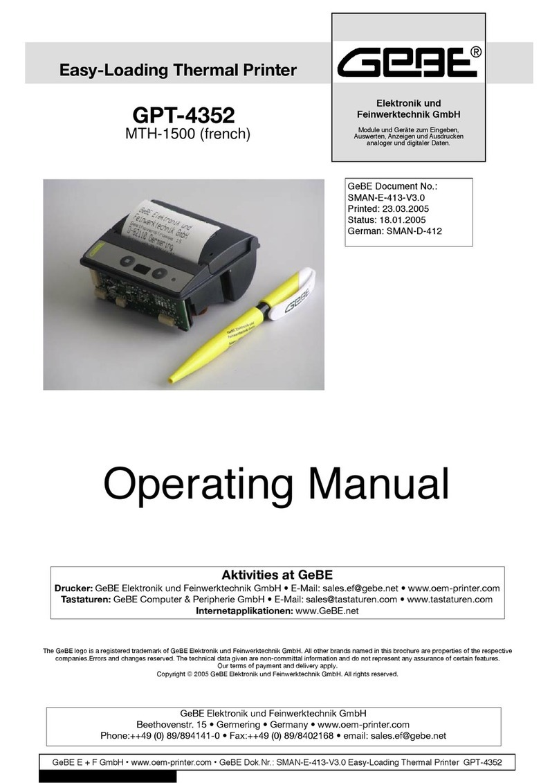
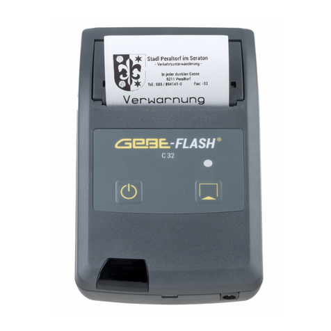
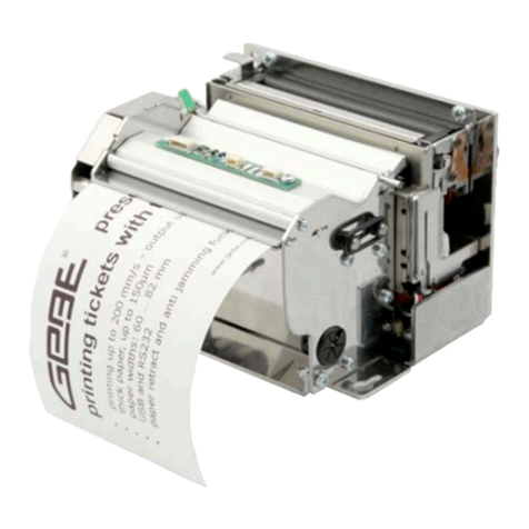
GeBe GPT-4352 User manual

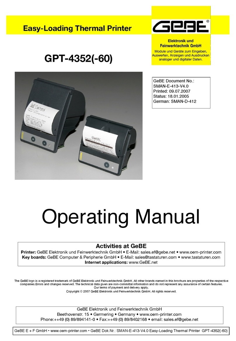
GeBE E + F GmbH • www.oem-printer.com • GeBE Doc.No.: SMAN-E-413-V4.1 Easy-Loading Thermal Printer GPT-4352(-60)
Operating Manual
GeBE Document No.:
SMAN-E-413-V4.1
Printed: 05.10.2009
Status: 05.10.2009
German: SMAN-D-412
GeBE Elektronik und Feinwerktechnik GmbH
Beethovenstr. 15 • Germering • Germany • www.oem-printer.com
The GeBE logo is a registered trademark of GeBE Elektronik und Feinwerktechnik GmbH. All other brands named in this brochure are properties of the respective
companies.Errors and changes reserved. The technical data given are non-committal information and do not represent any assurance of certain features.
Our terms of payment and delivery apply. Copyright © 2009 GeBE Elektronik und Feinwerktechnik GmbH. All rights reserved.
Activities at GeBE
Printer: GeBE Elektronik und Feinwerktechnik GmbH • E-Mail: [email protected] • www.oem-printer.com
Key boards: GeBE Computer & Peripherie GmbH • E-Mail: sales@tastaturen.com • www.tastaturen.com
Internet applications: www.GeBE.net
Mulde Mini
GPT-4352
GPT-4352-60
with controller system N78
Easy-Loading Thermal Printer

GeBE E + F GmbH • www.oem-printer.com • GeBE Doc.No.: SMAN-E-413-V4.1 Easy-Loading Thermal Printer GPT-4352(-60)
Content
2
1 Content
Chapter Description Page Chapter Description Page
2 Safety Instructions 3
3 Packing List 4
4 Installation 5
4.1 Installation in a front panel 5
4.2 Partial installation in plastic casing 5
4.3 Example for installation and application 5
5 Connecting the Printer 6
5.1 Connecting the power supply 6
5.2 Power Down 6
5.3 Connecting the charger 6
6 Printer Configuration 7
6.1 Configuration over Initialisation-TextPreserve TINIT 7
6.2 Entries into the "TINIT", which are primarily used 7
6.3 Solder Bridges 7
7 Interfaces 8
7.1 Serial Interface 8
7.1.1 Serial interface RS232 (V.24) at connector J2 8
7.1.2 Timing of serial RS232 /TTL interface 9
7.2 USB Interface 9
7.3 Parallel Interface 10
7.3.1 Centronics Adapter with SUB-D 25 pin Connector 10
7.3.2 PIN-seizure at the SUB-D 25 of the adapter 10
7.2.3 Timing of the Parallel Interface 10
7.4 Infrared Interfaces 11
7.5 Bluetooth® Wireless Technology 12
8 Operation 13
8.1 Which thermal paper is suitable? 13
8.2 Maintenance, Cleaning 13
9 Key Functions 14
9.1 Description 14
10 OPD-Menue® 15
11 Status Messages 17
12 Batch Files 18
12.1 Text or Graphics, Batch Files in the EEPROM 18
12.2 Configuration of the Printer 18
12.3 TMenue 18
12.4 TINIT 18
13 Option Magnetic Card Reader 19
14 Character Sets 20
14.1 GeBE Standard Character Set 20
14.2 Optional Character Sets 20
15 Error Detection 21
16 Options and Accessories 22
16.1 Options 22
16.2 Accessories 22
16.2.1 Mounting frames 22
16.2.2 Paper 22
16.2.3 Power supplies and charging devices 22
16.2.4 Batteries 22
16.2.5 Cables 22
17 Service and Maintenance 22
18 CE Certification 23
19 Technical Data 24
20 Mechanical Dimensions 24

Safety Instructions 3
2 Safety Instructions
•The device may only be opened or repaired by autho-
rized personal. Never open the device or carry out re-
pairs yourself. Always contact an authorized technical
servicer.
You can find all necessary service information in the
chapter "Service and Maintenance".
•Before the device is turned on, make sure that the
system voltage of your installation matches the
supply voltage of the device. The device characteris-
tics are printed on the name plate and in the technical
data.
- The name plate is located on the underside of the
device.
- For the technical refer to chapter 19.
•The peripheral devices that are connected to the inter-
faces and the DC circuits of this device have to meet
the requirements for safety extra-low voltage (SELV)
in accordance with EN/IEC 60950.
•Switching off the device does not completely discon-
nect it from the power supply. Your device is only dis-
connected completely, when the power plug is un-
plugged.
•Please make sure that the power supply cable is run
in a way that nobody trips over it, and it cannot be
damaged by other devices.
•During operation, surfaces in the surrounding area of
the print head may heat up. Therefore, direct contact
with the print head must be avoided to prevent bur-
ning accidents.
Do not put heat sensitive objects close to this heat
source.
•Avoid constant high humidity and condensation. Pro-
tect the device from being splashed and from getting
in contact with chemicals.
•Only use spare parts and accessories supplied or
authorized by GeBE. The use of unauthorized parts or
accessories may affect the function and safety of the
device. All parts included are listed in the chapter
"Packing List", while the original accessories are lis-
ted in the chapter "Parts and Accessories ".
•It is no longer possible to safely operate the device, if:
- the housing has been damaged
- moisture reached the inside of the device
- smoke is coming from the inside of the device
- the power supply cord is damaged
- the device stopped working properly
•It is prohibited to operate the device, if the housing is
damaged.
Turn off the device immediately, when a failure occurs,
as mentioned above, and contact GeBE customer ser-
vice. See chapter "Service and Maintenance".
•We explicitly state that all product liability and guaratee
claims are null and void, if the device has not been
used in accordance with the instructions in this opera-
ting manual or on the device itself!
•Risk of explosion in case of incorrect battery exchange.
•Please read how to safely exchange batteries in the
chapter "Exchanging Batteries".
•The printer versions with an infrared interface contain a
light emitting diode of laser category I. This infrared
transmitter does not pose a threat for the human eye or
skin, even with long periods of exposure.
•The device complies with laser category I in accordan-
ce with EN60825-1/A2:2001
Read operating manual before operation!
During installation: Always disconnect the power.
Safe operation of this device is only warranteed, if the instructions in this operating manual have been
complied with. Usage in accordance with the operating manual is required for product warranty.
If the user attempts to repair the product, all factory warranties will be null and void.
Only use manufacturer's parts and accessories! Make sure that the printer is saved against overvoltage
after EN/IEC 60950.
Laser Klasse I
GeBE E + F GmbH • www.oem-printer.com • GeBE Dok.Nr.: SMAN-E-413-V4.1 Easy-Loading Thermal Printer GPT-4352(-60)

GeBE E + F GmbH • www.oem-printer.com • GeBE Doc.No.: SMAN-E-413-V4.1 Easy-Loading Thermal Printer GPT-4352(-60)
Packing List
4
3 Packing List
All printer sets GPT-4352(-60) contain:
-tansparent LEVER (exchangeable)
- 5 paper rolls: GPR-T01-058-031-007-060A resp. GPR-T01-058-060-007-060A for GPT-4352-60
- operating manual: SMAN-E-413
In addition the different sets contain:
SET1 GPT-4352-LV-82-24-LC-at
• GKA-406: RS232 interface cabel, 500 mm
• GKA-410: Power cable,
one side open, 250 mm
SET2 GPT-4352-LV-82-24-V.24-EVAL-at
• GKA-406: RS-232 interface cable 500 mm
• GKA-416: Connecting cable for charger,
190 mm
• GNA-4.8V-1,6Ah-NiMH: Battery,
4x Mignon (AA)
• GNG-6V-0.8A-U: Charger
SET3 GPT-4352-LV-82-24-SPI(4,5V)-EVAL-at
• GKA-407: Connecting cable 12pol.
to Centronics Adapter
• GPT-4382-10: Centronics Adapter
25 pol Sub-D Stift
• GKA-410: Power cable,
one side open, 250 mm
GPT-4352 GPT-4352-60
SET1 GPT-4352-60-LV-82-24-LC-at
• GKA-406: RS232 interface cabel, 500 mm
• GKA-410: Power cable,
one side open, 250 mm
SET2 GPT-4352-60-LV-82-24-V.24-EVAL-at
• GKA-406: RS-232 interface cable 500 mm
• GKA-416: Connecting cable for charger,
190 mm
• GNA-4.8V-1.6Ah-NiMH: Battery,
4x Mignon (AA)
• GNG-6V-0.8A-U: Charger
SET3 GPT-4352-60-LV-82-24-SPI(4,5V)-EVAL-at
• GKA-407: Connecting cable 12pol.
to Centronics Adapter
• GPT-4382-10: Centronics Adapter
25 pol Sub-D Stift
• GKA-410: Power cable,
one side open, 250 mm
SET4 GPT-4352-LV-82-24-IR2-EVAL-at
• GCT-4382-20: external IR- adapter
• GKA-408: connecting cable to external IR
• GKA-416: connecting cable for charger,
190 mm
• GNA-4.8V-1.6Ah-NiMH: battery, 4x Mignon
(AA)
• GNG-6V-0.8A-U: Charger
SET4 GPT-4352-60-LV-82-24-IR2-EVAL-at
• GCT-4382-20: external IR- adapter
• GKA-408: connecting cable to external IR
• GKA-416: connecting cable for charger,
190 mm
• GNA-4.8V-1.6Ah-NiMH: battery, 4x Mignon
(AA)
• GNG-6V-0.8A-U: Charger
While unpacking, check if all parts on the packing list are present and undamaged. Make sure that all parts deli-
vered are removed from the packaging. Claims for compensation that are based on damage that occured during
shipment can only be asserted, if the delivery service is notified immediately.
Please write a damage report and send it back to the supplier together with the defective part(s).
SET5
GPT-4352-LV-82-24-V.24-LC-at-DC/DC
• GKA-435: Power cable
• GKA-414: RS-232 TTL interface cable,
500 mm
SET5
GPT-4352-60-LV-82-24-V.24-LC-at-DC/DC
• GKA-435: Power cable
• GKA-414: RS-232 TTL interface cable,
500 mm

Installation 5
4 Installation
4.1 Installation in a front panel
The plastic housing of the GPT-4352 printer can be in-
stalled with two screws in an easily done cut-out of a
front panel with up to 4 mm thickness. The contact sur-
face is flat. The edge of the housing juts out by 1 mm,
covering the space between the panel and the housing.
The housing is pushed into the cut-out from the outside,
and then easily screwed on.
The two holes of 2.8 mm diameter allow the use of
M2.5 screws.
4.2 Partial installation in plastic casing
As shown in the picture, the printer housing can also be
installed at the edge of a casing. This installation variant
has the part of the printer housing that contains the pa-
per roll extending beyond the unit casing. This saves
room in the device casing for the installation of other
components.
To facilitate installation in different casing shapes, the
outer wall of the paper storage was left smooth below
the bearing collar. The housing can project about 19 mm
from the casing edge, since about half of the paper sto-
rage can be used, right up to the slanting slot for inser-
ting the mounting plate.
4.3 Example for installation and application
As the pictures show, the installation types are almost
unlimited. The advantage of the compact thermal printer
Mini Mulde in its plastic housing consists above all of
the fact that it becomes possible to use the practical Ea-
syloading technology of the printer mechanisms also in
applications with smaller numbers of items.
For this small GeBE-printer a paper rewinder is
available, so that also a printer with presentation stage,
like shown above, can be used e.g. in a control panel
housing. The Mini MULDE is used also in the Desktop
Printer Series POCKET and is suitable for Handheld
computers with printing station.
Application in a pocket printer with infrared interface.
GeBE E + F GmbH • www.oem-printer.com • GeBE Dok.Nr.: SMAN-E-413-V4.1 Easy-Loading Thermal Printer GPT-4352(-60)

GeBE E + F GmbH • www.oem-printer.com • GeBE Doc.No.: SMAN-E-413-V4.1 Easy-Loading Thermal Printer GPT-4352(-60)
Connecting the Printer
6
5 Connecting the Printer
During installation:
Always disconnect from power!
5.1 Connecting the power supply (3)
The printer can be supplied with fixed voltage from a power supply
or a battery. Battery or power supply are plugged into the same
connector. Through the voltage supply connection, the printer can
be supplied with voltages between 3.5 V (for printers with Centro-
nics adapters with 4.5V) and 7.2 V. The supply for the logic chip is
produced on the board. The power cable GKA-410, included in sets
1 and 3, is connected to the connector J4 (3 red wires for + 3.5 -7.2
VDC, 3 black grounding wires, and one white cable for an NTC 6.8
KOhm of a Ni-MH battery). For simple power connections, the white
wire remains unconnected. We recommend keeping the length of
the line as short as possible. The longer the line, the higher the line
resistance, causing bad print quality or even printer failure.
5.2 Power Down
Starting with hardware version V1.4c the standard version does not support the power-off mode.
The controller comes with different levels of power saving modes (power down modes):
• Idle mode (8 mA typical)
• Sleep mode (20 µA typical)
• Power-off mode (0.1 µA typical), optional configuration required
During the receiving of data and during printing the controller is in an active status.
With the parallel interface, the ballast resistor R35 is not part of the standard configuration.
Connect jumper J3 for idle mode.
Remove jumper J3 for sleep mode.
Power-off logic ist not in the standard configuration (replaced by R37).
5.3 Connecting the Charger (5)
EVAL printers have a standard charging circuit for 4 Ni-MH cells. An operation with 3 or 5 cells is also possible.
The charging is performed by the uncontrolled plug-in power supply GNG-6V-0,5A-U that has a special internal re-
sistance. It is connected through the cable GKA-416 to the connector J1. The charging time for a 1500 mA/h bat-
tery will be about 5 hours. During the charging process, the LED on the control panel will display different pulses
that show, whether the fast or trickle charging mode is active.
Never use a fixed-voltage power supply for charging the batteries. The charging circuit is a "simple switch control",
meaning that the current limitation is not done in the charge control of the printer, but in the plug-in power supply.
Please use the suitable GeBE power supply GNG-6,0V-0,5A-U. In case of technical questions, please contact the
GeBE technic support (see chapter 17).
Designations:
1 Infrared (if equipped)
2 Connection winder
3 Connection power
4 SPI
5 Connection charger (Akku)
6 Connection RS232 / V.24
Avoid confusing the connection poles, because it can cause imme-
diate damage to the printer. Carefully check the power supply con-
nection before you turn on the printer.

GeBE E + F GmbH • www.oem-printer.com • GeBE Doc.No.: SMAN-E-413-V4.1 Easy-Loading Thermal Printer GPT-4352(-60)
Printer Configuration 7
6 Printer Configuration
6.1 Configuration over Initialisation-TextPreserve "TINIT " (Software Switch)
All commands for initializing the controller are filed in the text file "TINIT ". TINIT is available in the flash memory
of the printer and in the EEPROM (Note: Low-priced controllers with minimal functionality may not have an EE-
PROM). An entry in the EEPROM cancels entries in the Flash. For example, if a printer is to print double height
and inverse in data mode, the relevant commands are entered in the text file "TINIT". After a RESET, the controller
will first carry out its basic initialization, read the solder bridge settings, and then process the commands in the
"TINIT". Therefore, the commands in the "TINIT" have final authority regarding the valid settings. Custom settings
can also be achieved through entries in the text file "TINIT". If an EEPROM is available, "TINIT" can also be alte-
red through an interface.
The basic initialization of the controller corresponds with the following instructions that are initially not entered in
the "TINIT: <ESC> "A"; <ESC> "D" "0"; <ESC> "H" "0"; <ESC> "I" "0";
<ESC> "L" "0"; <ESC> "M" "0"; <ESC> "N" 0 0; <ESC> "P" 1; <ESC> "S"0; <ESC> "W" "0".
6.2 Entries into the "TINIT", which are primarily used
Comm. (ASCII)
Comm. (hex)
Function
<ESC>"Y"n
<ESC> "[" $40$18
1B 59 1E
1B 5B 40 18
Set blackening of the paper to a medium value of 25
Power consumption to 64 pixels, medium print dynamics and print quality
<ESC> "e" $05
<ESC> "r" "1" .... charging circuit configurated for NIMH cells
<ESC> "]" $0 $0
1B 45 05
Power-down after 5 seconds regardless of the buffer status, if enabled
1B 5D 00 00
Activate the transmitter of the serial interface
6.3 Solder Bridges Sleep Mode, Baud Rate, Text/Data Mode, Adapter SELECT
There are four 0-Ohm bridges and two jumpers on the controller board (optional) .
These bridges will each be inquired once during RESET.
Name
Meaning
Comment
Br9
BR204
enable Power
Down
text/data mode
Without Br9, the controller after a Power Up in
sleep modus
Data mode: printing rotated by 180°, first line at the
bottom page margin
Default: connected (disable)
Default: open (text mode)
BR203
BR201/
BR202
RN1
R9
Br206
Br205
RS232/Centr
Baud rate
Choice, if the RS232 or the Centronics through SPI
(GCT-4382-10) is active.
Signal- and
Handhake lines
V ADAPTER
Select
Equipped with TTL levels for the serial interface
Pin 4 of the serial interface can either be connected
with RTS ( Handshake input of the controller) or
with Vcc or Vp (power supply for external interface
adapter)
only connected on version SPI/Centro-
nics
Default: open (OFF)
Other baud rates on request.
Always inquired during RESET.
only connected on version TTL/serial and
SPI/Centronics
Standard: only R9 assembled - Handsha-
ke entry used for wake-up
Option: only Br206 connected - Vp at J2 /
Pin 4
Option: only Br205 connected- Vcc at J2
/ Pin 4
Br221
/DTR_Blue
Over this line the controller sends the signal for
Sleep modus of bluetooth Modul GSW-Blue1.
Default: open -
Option: only Br221 connected -
/DTR_Blue at J2 / Pin 4
Baud
BR201
BR202
Br201, Br202, Br203 closed and Br204 open
Br202, Br203 closed and Br201,Br204 open: activate
the OPD-Menue®
9600 19200
OFF
OFF
ON
OFF
115200 57600
ON
ON
OFF
ON
Jumper J3 zur Auswahl des Power Down Modus
Name
Meaning
Comment
J3
Power Down
Mode
Determines together with Br9, if idle mode,
sleep mode, or power-off mode is going to be
used.
Standard: plugged in = Idle Mode in
combination with assembled Br9.
open = Sleep Mode

GeBE E + F GmbH • www.oem-printer.com • GeBE Doc.No.: SMAN-E-413-V4.1 Easy-Loading Thermal Printer GPT-4352(-60)
Interfaces • Serial Interface
8
7 Interfaces
7.1 Serial Interface
7.1.1 Serial interface RS232 (V.24) at connector J2
Connector at printer: JST-SH (5pin). >>> Cable: GKA-406: The other end has a 9 pin SUB-D socket.
The assignment is 1:1, matching the serial interface of the PC.
Please note that the DSR and the DCD are terminated on some interfaces.
PIN-seizure
Pin Signal Input/Output Comment
Assignment
Cable GKA-406
D-SUB 9 Pin
1
2
GND signal
TXD
GND
I
Print data
5
3
3
4
Selection
through
BR5
RXD
RTS
O
I
+3.0V digital
+3.0V -7.2V power
O
O
Error reports and Xon/Xoff messages
Handshake input of the controller (Standard: Reactivation Function)
2
7
Supply for external adapter
5
CTS
O
If the level is logic-true, the controller can receive data.
8
1,4,6,9 = NC
RS232
The interface cable that comes with the set connects plug-in connector with the RS232 connection (COM inter-
face of a PC) on the other end. An open-ended cable with 5 single wires is available as an option.
TTL
For OEM, a special version with 3.3V TTL levels is available.
GeBE COM
In this setting, the printer uses the GeBE - Ir protocol for communicating. The protocol can be used through the
RS232 as well as the TTL. Through the CRC protected transmission blocks, a secure data connection can be re-
alized.
Also see: Infrared Interfaces. GeBE-Doc.No. MAN-E-395
ArtikelNr.
12165
12186
11336
12178
12828
12828
12481
12485
12482
12790
12791
Nomenclature
Interfaces
GPT-4352-LV-82-24-V.24-at
USB
GPT-4352-LV-82-24-V.24-EVAL-at
GPT-4352-LV-82-24-IR2-EVAL-at
GPT-4352-LV-82-24-TTL(4,5V)-EVAL-at
GPT-4352-LV-87-24-USB-at
X
GPT-4352-LV-87-24-USB-EVAL-at
GPT-4352-60-LV-82-24-V.24-at
X
GPT-4352-60-LV-82-24-V.24-EVAL-at
GPT-4352-60-LV-82-24-TTL(4,5V)-EVAL-at
GPT-4352-60-LV-87-24-USB-at
GPT-4352-60-LV-87-24-USB-EVAL-at
X
X
RS232, V.24
X
TTL (3,3V on request)
Infraredon board with plug
SPI e.g. for Centronics
X
X
X
X
X
X
X
X
X
X
X
X
X
X
Batteries
8 KByte EEPROM*
LItion
Features
NiMH charging circuit
Sleep Modus
X
X
X
X
X
X
X
X
X
X
X
Rewinder control
Z/Zeile: 24 (32, 42, 54)
X
Colour RAL7016
X
X
X
X
X
X
X
X
X
X
X
X
X
X
X
X
X
X
X
X
X
X
X
X
X
X
X
X
X
X
X
X
X
X
X
X
X
X
X
X
X
X
Overview
Operating the printer at extremely slow speed (<5 mm/sec.) special settings might be necessary.
Please contact our technical support.

GeBE E + F GmbH • www.oem-printer.com • GeBE Doc.No.: SMAN-E-413-V4.1 Easy-Loading Thermal Printer GPT-4352(-60)
Serial Interface RS232/TTL Interface • USB Interface 9
Serial Data Format
Standard:
• 9,600 Baud
• 8 Datenbit
• No Paritybit
• 1 Stopbit
LSB MSB
Start StopPar Start
0 1 2 3 4 5 6 7
Bit
1 Character: (1Start, 8 Data, 1 Parity, 1 Stop)
"1" (Mark)
"0" (Space)
Attention : the standard configuration has no paritybit
Attention : the standard configuration has 1 stopbit
Signal Level on TTL interface Level on RS-232 interface
"1" (Mark) +5V (TTL-level) -3V ... -12V
0V (TTL-level) +3V ... +12V
"0" (Space)
Selectable Data Formats
• 1,200, 2,400, 4,800, 9,600, 19,200,
38,400, 57,600 and 115,200 baud
• 7/8 data bits
• odd, even, non parity bit
• 1, 2 stop bit
• TX line turned ON/OFF
7.1.2 Timing of serial RS232 /TTL interface
The standard timing is shown in the picture below.
The Data format can be set via Menue (only printers
with EEPROM).
7.2 USB Interface
USB Printer Class
The USB device class is "Printer Class".
When plugged in, the PC will report "USB printer sup-
port" and install a "USB001"USB port.
Either the standard printer driver of the "system78" or the
port monitor can be used. During installation of the prin-
ter driver, it can be easily guided onto the USB port.
Windows® XP and Windows® CE handle the nu-
meration of a printer differently. Therefore, the prin-
ter must be conficurated to the operating system
before delivery.
USB Specification
Device type
USB
Power consumption
V1.1 ( V2.0 compatible)
Vendor specific device or printer class
Full speed 12 Mbit/s
no printing
USB active / printer active
USB active / printer sleeping
USB suspend / printer sleeping
Typ.
30 mA
25 mA
300 µA

GeBE E + F GmbH • www.oem-printer.com • GeBE Doc.No.: SMAN-E-413-V4.1 Easy-Loading Thermal Printer GPT-4352(-60)
Parallel Interface 10
7.3 Parallel Interface
Name
Meaning
Comment
BR1 or
J3
BR2 or
J3
Feedback of the AUTO_LF output of the host on SELECT:
Allows a Windows system to report printer - SELECT
back to itself.
SELECT interrupt
BR1 : default: open
J3 : default: 2-3 open, auto LF not fed back
to Select.
BR2 : default: open
J3 : default: 1-2 closed, select active
7.3.1 Centronics Adapter with SUB-D 25 pin Connector
The cable GKA-407 connects the adapter with the printer (at J5).
The cable GKA-302 produces a 1:1 connection of the adapter and the parallel port of a PC.
7.3.2 PIN-seizure at the SUB-D 25 of the adapter
Pin Signal Input/Output Comments
1
2
Strobe/
DB0
I
I
Accepting data DB0 ..7 with rising edge
3
4
5
6
DB1
DB2
I
I
DB3
DB4
I
I
7
8
9
10
DB5
DB6
I
I
DB7
/Acknowledge
I
O
11
12
13
14
BUSY
Paper End
O
O
Select
Auto Line Feed
O
I
Becomes high with the falling edge of /Strobe
See error messages
See error messages
Can be connected with select (Windows operation)
15
16
17
18-25
/Fault
/Input-Prime
O
I
Select in
GND digital
I
See error messages
used for initiating Reset
used for initiating the wake up sequence
7.2.3 Timing of the Parallel Interface
Time Name
min (µs)
typ (µs)
max (µs)
Comments
Tack
Tba
Ackn.pulse width
Delay busy ackn.
17
5.5
Tbs
Tdsu
Thold
Tsb
Busy Setup
Data Setup
0.5
0.5
Data hold
delay Strobe-Busy
0.5
0.5
Time before the next strobe
With open-collector triggering, the minimum time is 3.5 µs. This value can be changed by integratingdifferent RC filters.
Tstrb
Strobe pulse width 0.5
BB
BBuu
uuss
ssyy
yy
DD
DDaa
aatt
ttee
eenn
nn
SS
SStt
ttrr
rroo
oobb
bbee
ee//
//
AA
AAcc
cckk
kknn
nn//
//
Tstr b
Thold
Tsb
Tack
Par allele Schnittstelle
Tba
Tdsu
Tbs
Adapter GCT-4382-10 with
Centronics Interface

GeBE E + F GmbH • www.oem-printer.com • GeBE Doc.No.: SMAN-E-413-V4.1 Easy-Loading Thermal Printer GPT-4352(-60)
Infrared Interfaces
11
7.4 Infrared Interfaces
The following protocols can be used:
• IrDA: IR LPT (printer service)
IR COMM 9 wire (optional)
Also see: www.irda.org
• GeBE-IR: Simple, error-proof, bidirectional,
dot to dot IR-protocol.
GeBE-Doc.No. MAN-D-394
• HP-IR: Unidirectional IR transmission
GeBE-Doc.No. MAN-D-416
All standard versions of the printer have the hardware
for an IR transmitter/receiver installed, so the protocols
GeBE-IR and IrDA are available for all standard printers
of the series GPT-4352.
The internal IR tranceiver is installed directly below the
red foil window (10). The GPT-4352 has an LED next to
the transceiver that signals any IR communication. It is
important to consider that infrared transmissions only
work "at sight". The radiation angle is about +/-15 de-
grees. The transfer distance, which also strongly de-
pends on the efficiency of the opposite side, is about
0.6 meter.
Use of the Sleep Mode
In the setting "IrDA "or "GeBE IR", the IR receiver will
even be active in the sleep mode, so the device will not
have to be switched on explicitly for printing. The po-
wer consumption of the printer is only about 25µA in
this mode. However, the printer should still be turned
off during long periods of inactivity.
GeBE -IR Protocol
The GeBE-Ir protocol is a simple, error protected infra-
red protocol. The data transmission is processed in
CRC protected blocks.
With each transmission confirmation, the printer status
is sent back to the host.
The implementation is easy to realize. The protocol is
disclosed.
IrDA Protocol
The printer works with the protocol service IrLPT. Here
the printer doesn't send back.
A bidirectional Service "IrCOMM 9 wire" ist available on
request.
In the menu setting, the selected baud rate represents
the maximum baud rate. If 57,600 baud is selected, for
example, the printer will start to communicate with
9,600 baud and then switch up to 57,600 or 38,400
baud, depending on the transmitter.
The maximum baud rate of 115,200 should only be re-
duced, if transmission problems occur.
When an infrared transmission is interrupted, the prin-
ter will look for the transmitting master device for about
20 seconds in order to complete the transmission. After
that, the stack is reset, and new inquiries are answered.
Driver for IrDA
Windows® 98 / ME / NT / 2000 / XP
Driver for Windows are available on our Websites.
Driver support for WIN CE is available under:
www.fieldsoftware.com oder
www.Bachmannsoftware.com
Driver support for PALM OS and Symbian Serie 60 in-
struments is available under:
www.Bachmannsoftware.com
IrComm Services
Uncooked Services Cooked Services
IrLPT
3-wire Raw
Centronics
IEEE 1284
3 - wire
9 - wire
IrDA Data Specification
Radiation output
Min. input radiation intensity
Max. input radiation intensity
Peak wave length
Safety
Complies: IrDA V1.0 Standard Power SIR
min
40
max
100
4
500
Complies with IEC 825-1 class 1 (EN 60825) eye safety specifications
870
mW/sr On-axis
W/cm2
mW/cm2
v<(±15° )
v<(±15° )
nm
Range
IrDA
Interface parameters
GeBE-IR
Interface parameters
0.01
IrDA: automatic setting in accordance with IrDA ; 9,600, 38,400,
57,600, or 115,200 Baud
0.6
GeBE IR-Protocol: 9,600; 38,400; 57,600; or 115,200 baud,
8 data bits, non parity, 1 stop bit
m

12
GeBE E + F GmbH • www.oem-printer.com • GeBE Doc.No.: SMAN-E-413-V4.1 Easy-Loading Thermal Printer GPT-4352(-60)
Bluetooth® Wireless Technology
7.5 Bluetooth® Wireless Technology
The GPT-4352 with BT meets the BT specification V1.1
class 2, attaining a transmission range of about
10-15 m. On free field longer ranges can be reached.
The printer can be operated with a customary BT
dongle that comes with a virtual COM port driver.
A RS232 remote receiver is available on request.
Operation
The printer responds to an inquiry scan with its name
"GPT-4352" and its BT address. However, it can also be
addressed directly, without a scan, with its BT address.
A "BT connect" activates the printer. The printer will
maintain a connection until it goes into sleep mode. The
online power consumption of the printer with an active
BT link is about 35 mA. The sleep mode disconnects an
active connection and activates the BT sniff mode. In
this mode, the printer scans its environment for
possible calls every 1.25 seconds. During these inquiry
scans, it remains visible and responsive. It will then take
about 2-3 seconds to establish a connection.
The power consumption in this mode is about 1.5 mA.
When the printer is reactivated through the feed button,
the BT tranceiver will remain in sniff mode. After the set
time period, the printer will go back into sleep mode.
We recommend to set the sleep time to "1 minute".
If you are not planning to operate the printer for several
days, switch it off with the OFF/NEXT key. After the po-
wer is turned on, it will take a minimum of 10 seconds
for the printer to become ready to receive data.
The printer does not ask the master for any authentica-
tion.
Should your transmitter require a PIN number, type in
"0000".
Please always set your printer to 115,200, n, 8,1.
Drivers
Windows 98 / ME / NT / 2000 / XP
Windows drivers can be found on our website.
www.oem-printer.com
Driver support for WIN CE is available under:
www.fieldsoftware.com oder
www.Bachmannsoftware.com
Driver support for PALM OS and Symbian Serie 60 in-
struments is available under:
www.Bachmannsoftware.com
This printer contains a 2.4 GHz radio transmitter. For health reasons, a distance of at least 1.0 cm must be
kept between the printer surface and the body of the user, except hands, fists, feet, and joints.
As a precaution, any body contact during operation should be kept to a minimum.
Bluetooth Specification
Funk sending level
Range
Profile
Printer current consumption
V1.1
4 dBm (class 2)
approx. 10 -15 m
SPP serial port profile
no printing min.
Active link/data traffic at 115 kbps
Active link
50 mA
25mA
Typ. max.
62 mA
35 mA
95 mA
55 mA
Idle
Printer activ/ BT sniff mode
18mA
5 mA
Sniff mode (1.25 sec. scan)
Power off
1 mA
0,3 µA
25 mA
7 mA
40 mA
15 mA
1,3 mA
0,7µA
2,5 mA
2,0 µA
CE statement:
The BlueRS+I complies with the European safety regulations IEC 60950,
and EMV regulations ETS 300 328-2 and ETS 301 489 -1 und -17.
FCC statement:
The printer contains a BlueRS+I OEM serial adapter with the FCCID: RFR-BRSI / IC: 4957A-BRSI .
The BlueRS+I complies with part 15 of the FCC rules and with RSS-210 of Industry Canada.
The BlueRS+I has been qualified as a product in accordance with the Bluetooth®Qualification Program (BQP).

13
GeBE E + F GmbH • www.oem-printer.com • GeBE Doc.No.: SMAN-E-413-V4.1 Easy-Loading Thermal Printer GPT-4352(-60)
Operation • Maintenance
8 Operation
8.1 Which thermal paper is suitable?
The printer is specified for a paper width of 57.5 ± 0.5 mm, with a weight
of 60 g/sqm. GeBE is offering suitable paper rolls (GPR-T01-058-031-007-
060A resp. GPR-T01-058-060-007-060A for GPT-4352-60) as part of the
standard program. Other papers may not be suitable for use.
Thermal papers that are resistant against water, grease, or alcohol are
available for special applications. We will gladly assist you in your selec-
tion of the suitable thermal paper.
How do I insert the paper?
Use paper rolls that are coated on the outside with a width of 57.5 mm ±
0,5 mm and a winding diameter of 31 mm and 60 mm for GPT-4352-60.
Standard GPT-4352: GPR-T01-058-031-007-060A
Standard GPT-4352-60: GPR-T01-058-060-007-060A
1. Unwind about 10 cm (4") of paper from the roll. Keep the layers wound
tightly.
2. Open the printer cover by slightly pressing the LEVER in the cover up-
wards. The print roll is lifted from the mechanism together with the co-
ver. The cover is now easy to open.
3. Insert the paper roll in the paper storage, so the outside shows toward
the printer mechanism. Only this outside can be printed on.
4. Close the cover by applying strong pressure. You can hear it snap shut.
Now you can rip off paper at the tear bar without the cover opening up
or the paper sliding through the print head.
1.
2.
3.
4.
8.2 Maintenance, cleaning
After larger print efforts, depending on the paper quality and adverse en-
vironmental conditions, it may be necessary to clean the print head, sen-
sor, and the platen roll, especially, if some areas are no longer printed
properly.
• Open paper supply lid and remove paper roll.
• Loosen dirt particles at the paper sensor and the tear-off bar with a
small brush.
• Blow forcefully into the paper supply compartment in order to remove
the coarse dust.
• Soak Q-tip in isopropanol (IPA) and clean the print head, or use print
head cleaning pin/cleaning card.
• Other stubborn debris can also be removed with a Q-tip (IPA).
On principle the printer has to be kept dust-free.
Never use sharp objects for cleaning. This might cause damage to the
print head.
Do not touch the print head. This might cause damage through
electrostatic charge.
Which side of the thermal paper can be printed on?
On the paper roll, the side to print on is, in almost all cases, the outside.
If you should have any doubts, just do the fingernail test:
Quickly drive the edge of a fingernail with slight pressure over the paper.
The thermosensitive side will turn black as a result of the frictional heat.

GeBE E + F GmbH • www.oem-printer.com • GeBE Doc.No.: SMAN-E-413-V4.1 Easy-Loading Thermal Printer GPT-4352(-60)
14 Key Functions
9 Key Functions
9.1 Description of the key functions
The keys can have different functions depending on the
status – normal operation or print settings menu. The
time for which the button is held down is also an issue.
FEED / ENTER (1)
Through this key, the printer can be reactivated from
sleep mode, and the paper can be transported forward.
When the feed key is pressed, the printer will first feed
one line of the set font. If the key is held down for more
than 2 seconds, it will feed continuously.
Self Test
With this, the printer functions can be tested through a
printout. To start the self test the FEED Button {FEED}
(1) has to be held down for more than 3 seconds when
waking up the printer out of the Power OFF mode. The
interfaces won't be tested in this case. Software version
and character set will be printed out. For OEM special
printouts can be activated during this operation self
test.
OFF / NEXT Taste (3)
By holding down the OFF/NEXT key for more than 3
seconds during operation, the processing of batch file
T2 is initiated. In µ-P flash, the command for power-off
(after 1 second) is filed in batch file T2. This way, this
key is programmed as an OFF button for the printer
(controller with power-off mode).
Key FEED/ENTER
Key OFF/NEXT
Action
pressed
held down > 2s
not pressed
not pressed
paper feed by one line
continuous paper feed
pressed during power-on < 1s
held down during power-on
paper inserted > 2s
held down during power-on
no paper > 2s
pressed in hexdunp mode
no paper
not pressed
not pressed
reactivation, no paper feed
call T0 (self test)
not pressed
not pressed
call hexdump mode
hexdump mode end
not pressed
not pressed
pressed
key released after < 1s in nor-
mal paper mode
key held down > 3s
call T1
(default = form feed 1 line)
call T2
(default = power-off after one second)
pressed
call print settings menu
1.
2. 4.
3.
Designations:
1 FEED / ENTER button
2 IR window
3 OFF / NEXT button
4 Status LED (see chapter 11 "Status Messages")

15
GeBE E + F GmbH • www.oem-printer.com • GeBE Doc.No.: SMAN-E-413-V4.1 Easy-Loading Thermal Printer GPT-4352(-60)
OPD-Menue®
10 OPD-Menue®
The most important settings of the printer can be changed with a few key strokes using the OPD-Menue®
(OnPaperDisplay).
They can be called at any time, and can be quickly understood with the menu printout.
The inconvenient accessing of DIP switches and the programming through a terminal program are a thing of the
past.
The OPD-Menue®is operated with only two keys (OFF/NEXT and FEED/ENTER)
The OPD-Menue®is an editor of an initialization batch file "TMENUE" that is called before the "TINIT".
See chapter 12 "batch files".
Key FEED/ENTER
pressed
not pressed
pressed
Key OFF/NEXT
Action
not pressed
pressed
increasing the parameter
moving to the next menu item
pressed
leaving menu and saving settings
Menu Guide - Example:
Bold : printout of the menu
Normal: possible settings
Italic: comment
Welcome to the OPD menu 1.0 5
Setup timeout after 10 minutes
Actual printer settings:
Ubat: 52V
Tbat: 24°C
(displayed only with battery )
Firmware: GE-xxxx
Density 25
Speed: med (64)/low
Interface: RS232/USB/Blue
COM: 9600,n,8,Tx+
Sleep time: 5 sec
Font #: 1
Char. format: D0,W0,H0,S0,48
? Change actual settings
Press ENTER to change
Press NEXT to skip
Press NEXT+ENTER to save and exit
PRINTER SETUP:
Press ENTER to modify
Press NEXT to store and continue
Press NEXT+ENTER to save and exit
Density: 25 20, 25, 30, 35, 40, 45, 50, 90(2ply)
Speed/Quality: med 64/ low (Depending on the Printer typ)low (32)/med, med
(64)/med, med (64)/low, high (96)/low
Interface: RS232/USB/Blue RS232/USB/Blue, IrDA, GeBE-IR, GeBE-COM
Baudrate: 9600 1200, 2400, 4800, 9600, 19200, 38400, 57600, 115200.
COM parameter: n,8,Tx+ n, 7, Tx+ / o, 7, Tx+ / e, 7, Tx+ / n, 8, Tx+ / o, 8, Tx+ / e, 8, Tx+ /
n, 7, Tx- / o, 7, Tx- / e, 7, Tx- / n, 8, Tx- / o, 8, Tx- / e, 8, Tx-
Sleep Time: 5 sec
OFF, 5 sec, 30 sec, 1 min, 10 min, 1 h, 12 h, 32 h

GeBE E + F GmbH • www.oem-printer.com • GeBE Doc.No.: SMAN-E-413-V4.1 Easy-Loading Thermal Printer GPT-4352(-60)
Status Messages
16
Font #: 1 1, 2, 3, 4
Text orientat: Textmode (D0) Textmode (D0), Datamode (D1)
Char. size : W0/H0
W0/H0, W0/H1, W0/H2, W0/H3, W1/H0, W1/H1, W1/H2, W1/H3
Char. spacing : 0 0,1,2,3,4,5,6,7
Print width : 48 mm (Dependiong on type of printer)
48 mm, .... 32 mm
? Return to default settings
Press ENTER to change
Press NEXT to skip
Press NEXT+ENTER to save and exit
ONLY with clock option / clock connected
17.03.03 17:33
? Change date / time
Press ENTER to change
Press NEXT to skip
Press NEXT + ENTER to save and exit
RTC SETUP:
Press ENTER to modify
Press NEXT to store and continue
Press NEXT+ENTER to save and exit
00 .. 49 Year: 03
01 .. 12 Month: 11
01 .. 31 Date : 14
01 .. 07 Day : 7
00 .. 23 Hour : 13
00 .. 59 Minute : 33
1 00 : 00 ON
? Change alarm
Press ENTER to change
Press NEXT to skip
Press NEXT + ENTER to save and exit
ALARM SETUP:
Press ENTER to modify
Press NEXT to store and continue
Press NEXT+ENTER to save and exit
01 .. 07, * Day : 7 * : means periodic enterprise, e.g. if "day" is adjusted to *, each
day to the adjusted time an alarm is called
00 .. 23, * Hour : 13
00 .. 59, * Minute : 33
ON, OFF Mode: OFF

Status Messages 17
GeBE E + F GmbH • www.oem-printer.com • GeBE Doc.No.: SMAN-E-413-V4.1 Easy-Loading Thermal Printer GPT-4352(-60)
11 Status Messages
LED "STATUS" (green/red) (4)
The STATUS LED will flash green slowly, when everything is in order. It will flash red in regular intervals in case of a
failure. During fast charging, the STATUS LED will flash green in regular intervals, while it permanently glows green
during trickle charge.
Status messages of the printer through the interfaces
Besides the optical status messages displayed by the three LEDs on the control panel of the printer, messages are
also transmitted through the serial interface. Most of the time, they are sent as single ASCII characters that can be
analyzed by the host.
The following table shows all status messages.
Status
Messages
Serial
Interface
Comments
Feedback
through the
serial interface
on:off /flash frequency
fast: "S" app. 0.66Hz
medium: "M" app. 0.33Hz
slow: "L" app. 0.16Hz
Status LED
Faultless
operation:
After reset
After watch-dog
reset
Error end
"R"
"R"
"X"
1:31 / M
green
Level on the status lines only short-term during phase of initialization. Message: <XON> "R"
"X" (or error)>
Crashing program
also after hardware, software, and watchdog resets
Buffer empty
Buffer full
Synchronous
feedback
Battery char-
ging:
X ON
X OFF
all
characters
Formatting
Fast charge
Trickle charge
Errors:
"l"
"L"
"L"
"f"
start
"F"
error
end
Buffer emptied by 32 characters <DC1> = $11
Space for 22 more characters in buffer <DC3> = $13
Processing of synchronizing commands;
each transmitted character
off
LED permenently
on
LED flashes (1:3)
L := charge start l := end of charge
F := charge start f := end of charge
Paper end
Temp. low
Temp. high
Vp too high
"P"
"K"
"p"
"k"
"T"
"M"
"t"
"m"
Parity error
EE-OK
EE-invalid
EE-Password
"?"
"E0"
"E1"
"E2"
1:1 / S
red
After paper has been inserted, the printer waits for about 2s before printing
in order to have enough time to close the mechanism.
print head temperature too low
print head temperature too high
1:31 / M
green
Parity or framing error / no interruption of printing
EEPROM command completed without errors
Invalid text file no.
Wrong password for EEPRROM access
EE-Overflow
EE-Time-out
EE-KO
"E3"
"E4"
"E5"
IR Reception
Successful read
Unsuccessful
read
IR communication
Text file memory overflow
Programming time for EEPROM byte exceeded.
EEPROM not found
LED on
Reading magnetic cards
red
LED on 2sec.
3xshortLEDon
yellow
Chaging Voltage
Charging voltage (line)
LED on
yellow
LED is on if voltage is higher than 9 - 10 V in order to signal a valid charging voltage.

18
GeBE E + F GmbH • www.oem-printer.com • GeBE Doc.No.: SMAN-E-413-V4.1 Easy-Loading Thermal Printer GPT-4352(-60)
Batch Files
12 Batch Files
Almost all commands that the printer can receive
through the interfaces and then perform can be put into
the batch files. When a batch file is processed, the
commands it contains are added to the data stream of
the print program sequentially, as if they were coming
through the interface from outside. This way, all settings
that can be done by command can be processed via
batch file. Besides settings commands, batch files can
also contain text and graphics.
The file structure consists of one TINIT, which is proces-
sed with each system boot-up, as well as 10 files that
can be used freely, which are retrieved by command.
Some of these files can be addressed through additio-
nal events. If the controller has an EEPROM, it contains
a file structure that is identical to that of the program
memory (Flash).
When a filed is retrieved, the printer will check, if it con-
tains data in the EEPROM. If it does not, the file will be
processed in the Flash. This allows Flash files to be
over-written.
The following batch files are accessable:
Allocated in the Flash Memory, Factory Settings:
• "TINIT" ...settings after hardware RESET
• "T0 " .....self test through FEED key after reset
• "T1 " .....form feed through NEXT key <1 sec.
• "T2 " .....power-off through OFF key >3 sec.
• "T3 - T9" : unused
12.1 Text or Graphics, Batch Files in the EE-
PROM
For the printing of text and graphics, the GPT-4352 has
an 8 KB EEPROM (app. 6 KB can be used for logos),
and the GPT-4352 has a 32 KB EEPROM (app. 30 KB
can be used for logos).
It is recommended to store logos PCL compressed.
By using the Windows driver, compression rates of app.
3 - 4:1 can be achieved.
For comparison: Uncompressed full graphics of 5 cm
length take up 20 KB, while they only require app.
5,7KB when compressed.
Creating and Saving Logos:
A special printer driver is available for creating logos.
12.2 Configuration of the Printer with
TMenu and TINIT
After a hardware RESET (connecting the power supply),
the printer will check for a prescribed TMenu and/or
TINIT in the EEPROM. If it finds one or both, it will pro-
cess the batch file commands and will then be ready for
operation. If not, it will process the TMenu and/or the
TINIT containing the factory settings in the Flash.
12.3 TMenue
The OPD-Menue®is a printer function that allows the
user to edit the TMenu in the EEPROM. The TMenu can
only be changed through the OPD Menue®.
Structure of the TMenu:
<ESC>Y<18h> {density}
<ESC>[<DEZ64><DEZ48> {power consumption}
<ESC>]<DEZ115><DEZ40 {baud rate, settings}
<ESC>e<DEZ5><DEZ2> {power-down time}
<ESC>P1 {font}
<ESC>D0 {text orientation}
<ESC>W0<ESC>H0 {text size}
<ESC>S0 {text spacing}
<ESC>h48 {print width}
12.4 TINIT
The TINIT is always processed subsequent to the
TMenu. In the TINIT, other presets that were not incorpo-
rated in the menu can be executed. It also allows set-
tings to be blocked in the menu by repeating them here.
The following TINIT file is an example of a file that can be
modified by the user. Please ask us for further informati-
on.
The file will erase the TINIT, while printing out all actions
in italic at the same time.
Any commands can be entered in the TINIT.
Erase Tinit ...
<ESC>uUERAS
Special number S-xxx / Status 24nov03
Program tinit with GE-xxxx...
{Comments}
<ESC>s@PROG<00h><11h>
<ESC>r1<28h><3Ch><01h><12h> {charging parameters}
<A9h><01h><3Ch><01h><40h>
<19h><01h><85h><0Ah><8Ch>
All programmed!
If a command of the TMenu is repeated in the TINIT,
this value can no longer be changed through the menu.
By using these files in the EEPROM you are chan-
ging the standard factory settings.

19
GeBE E + F GmbH • www.oem-printer.com • GeBE Doc.No.: SMAN-E-413-V4.1 Easy-Loading Thermal Printer GPT-4352(-60)
Option Magnetic Card Reader
13 Option Magnetic Card Reader
EC Card
Track
2
2
2
2
3
Place
1-3
Content
identification 672
9-18
21-22
account number
year of expiration
23-24
1-4
month of expiration
identification (0159, EC card)
3
3
3
3
5-12
14-23
bank identification code
account number
37-40
41
remaining amount that can be withdrawn
final digit of the year of the last withdrawal
3
3
S-Card
Track
61-62
63-64
year of expiration
month of expiration
Place Content
2
3
3
Credit Card
x
1-4
like EC card
identification (0059, S-card)
9-24 like EC card
Track
1
1
1
Place
2-17
Content
credit card number
19-44
46-47
last name of the card holder
year of expiration
1
2
2
2
48-49
1-16
month of expiration
credit card number
18-19
20-21
year of expiration
month of expiration
Numeric Character Track 2 and 3
P 3210
1 0000
equals
0
Meaning
0 0001
0 0010
1 0011
0 0100
1
2
3
4
1 0101
1 0110
0 0111
0 1000
5
6
7
8
1 1001
1 1010
0 1011
1 1100
9
:
control
;
<
start sentinel
control
0 1101
0 1110
1 1111
=
field seperator
control
?
end sentinel
ALPHA Character Track 1
P 543210
1 000000
0 000001
hex
00
01
space
!
0 000010
1 000011
0 000100
1 000101
02
03
,,
#
04
05
$
%(start)
1 000110
0 000111
0 001000
1 001001
06
07
&
'
08
09
(
)
hex
0 100000
1 100001
20
21
@
A
1 100010
0 100011
22
23
1 100100
0 100101
24
25
B
C
D
E
0 100110
1 100111
26
27
0 101010
1 101011
28
29
F
G
H
I
1 001010
0 001011
1 001100
0 001101
0A
0B
*
+
0C
0D
,
-
0 001110
1 001111
0 010000
1 010001
0E
0F
.
/
10
11
0
1
1 101000
0 101001
2A
2B
0 101100
1 101101
2C
2D
J
K
L
M
1 101110
0 101111
2E
2F
1 110000
0 110001
30
31
N
O
P
Q
1 010010
0 010011
1 010100
0 010101
12
13
2
3
14
15
4
5
0 010110
1 010111
1 011000
0 011001
16
17
6
7
18
19
8
9
0 110010
1 110011
32
33
0 110100
1 110101
34
35
R
S
T
U
1 110110
0 110111
36
37
1 111010
0 111011
38
39
V
W
X
Y
0 011010
1 011011
0 011100
1 011101
1A
1B
:
;
1C
1D
<
=
0 011110
0 011111
1E
1F
>
? (end)
0 111000
1 111001
3A
3B
1 111100
0 111101
3C
3D
Z
[
\
]
0 111110
1 111111
3E
3F
^( field)
_
The magnetic card reader of the GPT-4352 can be used
for magnetic cards of the type ISO 3554. It reads up to
3 tracks simultaneously. The permissible swiping
speed is 10 - 100 cm/s.
The recording density and the number of bits per cha-
racter differ from one track to the next according to ISO
3554. They determine the maximum number of charac-
ters including start and stop characters that can be re-
corded on each track:
In accordance with the norm, track 1 and 2 are just read
during operation.
Track 3 is the only one that is also used for recording.
Operation
After the swiping of the card, the LED lights up for
about 2 seconds, if the card was read correctly. If an er-
ror occured, the LED will flash rapidly 6 times.
While the LED is on, another reading process is not
possible. After the LED has gone out, the internal buf-
fers are getting ready for the next reading process, wai-
ting for a new card to be swiped.
The printer puts out the card data for each track with a
header. The data set is concluded with a check sum.
The card data per track contains:
- the number of data on this track
- status byte (type of error, if occured)
- data
A detailed description can be found in the software
manual.
Applications
Track 1 and 2 for credit cards
Track 2 and 3 for Eurocheque
Track 2 for access control
Track 3 for time recording
The Magnetic Carsd Reader can be combinated with:
USB, Bluetooth, RS232/TTl, und IrDA-9 wire
The Magnetic Carsd Reader can not be combinated
with:
HP-Ir, GeBE-Ir and IrDA IrLPT
Track
1
2
bpi bit
210
75
7
5
3 210 5
Characters
79
40
107

20
GeBE E + F GmbH • www.oem-printer.com • GeBE Doc.No.: SMAN-E-413-V4.1 Easy-Loading Thermal Printer GPT-4352(-60)
Character Sets
14 Character Sets
The four character sets in the flash memory of a standard controller can be selected by command.
Other character sets on request. The Euro character is located at 16 hex.
14.1 GeBE Standard Character Set
Resembles IBM II Code Table 850
FontNo.
Dots(horiz./vert.)
characters/line
1
2
16 / 24 24
9 / 22 42
3
4
7 / 16 54
12 / 24 32
14.2 Optional Character Sets
The following character sets are available at this time and can be programmed into the FLASH memory of the µ-
processor in exchange for other character sets. Please send us you inquiry.
Optional character set: cyrillic, Based on: IBM code table 850
GeBE will gladly create other character sets on request.
Dots(horiz.x vert.)
characters/line
IBMII
IBMII
16 x 24 24
14 x 22 27
IBMII
IBMII
IBMII
IBMII 90°
11 x 22 34
9x 22 42
7x16 54
16 x 11 "24"
Kyr
Kyr
Kyr
16 x 24 24
14 x 22 27
11 x 22 34
Other manuals for GPT-4352
4
This manual suits for next models
1
Table of contents
Other GeBe Printer manuals

GeBe
GeBe GPT-435 User manual

GeBe
GeBe GPT-4443 User manual

GeBe
GeBe GPT-4352 User manual

GeBe
GeBe GPT-4673 User manual

GeBe
GeBe GeBE-MULDE Mini User manual

GeBe
GeBe GPT-4378-FLASH-70-iBT User manual

GeBe
GeBe GPT -4352 User manual

GeBe
GeBe GPT-4352 User manual

GeBe
GeBe GPT-6776 User manual

GeBe
GeBe GPT-437x-FLASH User manual

GeBe
GeBe GPT-4352 User manual

GeBe
GeBe GPT-4379-Flash-HQ User manual

GeBe
GeBe GPT-4673 User manual

GeBe
GeBe FLASH GPT-4378 User manual

GeBe
GeBe GPT-437 Series User manual

GeBe
GeBe GPT-4454 User manual

GeBe
GeBe GeBe-PIANO GPT-4633 User manual

GeBe
GeBe FLASH GPT-4378 User manual

GeBe
GeBe GPT-4389 User manual

GeBe
GeBe GPT-4352 User manual