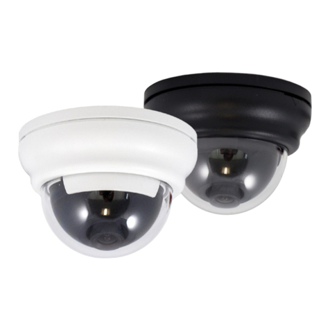
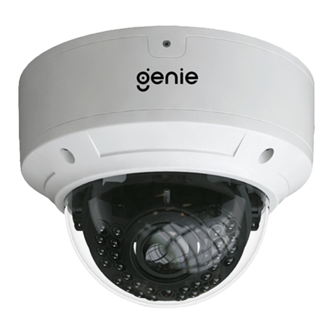
Genie VRD73IR User manual

Model: VRD73IR
True Day/Night
Vandal Resistant
IR Dome Camera
User Guide


- 3 -
True Day/Night Vandal Resistant IR Dome Camera
CAUTION
RISK OF ELECTRIC SHOCK
DO NOT OPEN
CAUTION:TO REDUCE THE RISK OF ELECTRIC SHOCK
DO NOT REMOVE COVER(OR BACK).
NO USER-SERVICEABLE PARTS INSIDE.
REFER SERVICING TO QUALIFIED SERVICE PERSONNEL.
ISO14001
CAUTION
RISK OF ELECTRIC SHOCK
DO NOT OPEN
CAUTION:TO REDUCE THE RISK OF ELECTRIC SHOCK
DO NOT REMOVE COVER(OR BACK).
NO USER-SERVICEABLE PARTS INSIDE.
REFER SERVICING TO QUALIFIED SERVICE PERSONNEL.
ISO14001
CAUTION
RISK OF ELECTRIC SHOCK
DO NOT OPEN
CAUTION:TO REDUCE THE RISK OF ELECTRIC SHOCK
DO NOT REMOVE COVER(OR BACK).
NO USER-SERVICEABLE PARTS INSIDE.
REFER SERVICING TO QUALIFIED SERVICE PERSONNEL.
ISO14001
The lightning flash with an arrowhead symbol, within an equilateral
triangle is intended to alert the user to the presence of uninsulated
dangerous voltage within the product's enclosure that may be of
sufficient magnitude to constitute a risk of electric shock to persons.
The exclamation point within an equilateral triangle is intended to alert
the user to the presence of important operating and maintenance
(servicing) instructions in the literature accompanying the appliance.
INFORMATION - This equipment has been tested and found to comply with
limits for a Class A digital device, pursuant to part 15 of the FCC Rules & CE Rules.
These limits are designed to provide reasonable protection against harmful
interference when the equipment is operated in a commercial environment.
This equipment generates, uses, and can radiate radio frequency energy and, if
not installed and used in accordance with the instruction manual, may cause
harmful interference to radio communications.
Operation of this equipment in a residential area is likely to cause harmful
interference in which case the user will be required to correct the interference at
his own expense.
WARNING - Changes or modifications not expressly approved by the
manufacturer could void the user’s authority to operate the equipment.
This installation should be made by a qualified service person and
should conform to all local codes.
CAUTION: To prevent electric shock and risk of fire hazards.
Do NOT use power sources other than those specified.
- 4 -
True Day/Night Vandal Resistant IR Dome Camera
Contents
Dimensions
5
8
5
6
9
7
11
10
37
38
General Features
Safety Instructions
Precautions
Installation
Specication
Troubleshooting
Menu Set Up
• OSD Control Keys
• Set Up Menu
• Menu Set Up
• Lens
• Exposure
• White Balance
• D-WDR/HSBLC
• 3D-DNR
• Day/Night
• Smart-IR
• Special
Exit
• Camera Title
• Adjust
• Mirror
• Motion Detection
• Privacy
• Sync
• Resolution
• Reset
• Return
12
11
35
14
35
15
36
17
18
19
22
22
24
25
25
28
31
32
33
34
35
Package Contents
Focus Adjustment

- 5 -
True Day/Night Vandal Resistant IR Dome Camera
Camera Dimensions
Package Contents
Φ150
Φ100
Φ150
114
56.5
VIDEO TEST CABLE 1EA SCREW TS T1, #8X38 & O-RING ASSY 4EA SCREW PH M4X8, BK, 3EA
TORK WRENCH T20 1EA
INSTRUCTION MANUAL 1EA GREEN TERMINAL 2P MAIL 1E
A
FOCUS CONTROL SCREW 1EA

- 6 -
True Day/Night Vandal Resistant IR Dome Camera
Adjusting screw for focus(Near-Far)
Adjusting screw for fix(Fix)
Adjusting screw for angle of view(TELE-WIDE)
Focus Adjustment
1) Loosen the screw in the middle.
2) Ajust angle of view by using the controller.
3) Adjust focus by using the controller.
4) Tighten the screw in the middle.

- 7 -
True Day/Night Vandal Resistant IR Dome Camera
Camera + Installation
Cable Connection
TAPPING SCREW #8X38, 4EA
MACHINE SCREW M4X8, 3EA
Video (UTP)
Video Output Connector
Power Input Terminal : AC24V/DC12V

- 8 -
True Day/Night Vandal Resistant IR Dome Camera
General Features
Presets
Presets (Outdoor, Indoor, Elevator, Lobby, Hallway & Low Light). Used for a quick and easy setup
according to the prevailing installation environment.
3D Motion DNR Function
When movements in the picture are detected, 3D-DNR AUTO can reduce the level of noise; with a
low-level DNR setting. Opposingly, if there are no moving picture elements, noise can be reduced
using a high-level DNR setting.
620 TV Lines
The combination of a Sony Super HAD CCD image sensor and a DNR DSP provides an excellent
resolution of 620 TV lines.
D-WDR (Digital Wide Dynamic Range)
D-WDR is a powerful and ultra advanced technology that captures cleaner and superior high
Resolution pictures, even where images appear dark due to a strong backlight presence.
Auto Defect
When set to AUTO this function corrects black and white dots caused by pixel failure, in real time,
when Sens Up is on. When changing from OFF to AUTO, you will see the reduction in pixels which
are permanently on (white dot) and those permanently off (black dot).
Smart-IR (IR Models Only)
No Image Saturation. Vivid Images in Darkness. "Smart IR” gives a very sharp video image in
darkness. This technology eliminates video image IR saturation of close objects by controlling the
IR sensitivity.
Additional Functions
OSD - On Screen Display menu with multi-language support.
Privacy Masking - 8 Zones
Sens-Up - x1024
3D-DNR
Digital
Reduction
Noise
0.000001 Lux
Illumination
Minimum
Resolution
Horizontal
620
Wide Dynamic Range
Digital
WDR
Backlight
Compensation
BLC
DSP
3D-DNR
OSD
Smart-IR
3D-DNR
Digital
Reduction
Noise
0.000001 Lux
Illumination
Minimum
Resolution
Horizontal
620
Wide Dynamic Range
Digital
WDR
Backlight
Compensation
BLC
DSP
3D-DNR
OSD
Smart-IR
3D-DNR
Digital
Reduction
Noise
0.000001 Lux
Illumination
Minimum
Resolution
Horizontal
620
Wide Dynamic Range
Digital
WDR
Backlight
Compensation
BLC
DSP
3D-DNR
OSD
Smart-IR
3D-DNR
Digital
Reduction
Noise
0.000001 Lux
Illumination
Minimum
Resolution
Horizontal
620
Wide Dynamic Range
Digital
WDR
Backlight
Compensation
BLC
DSP
3D-DNR
OSD
Smart-IR
3D-DNR
Digital
Reduction
Noise
0.000001 Lux
Illumination
Minimum
Resolution
Horizontal
620
Wide Dynamic Range
Digital
WDR
Backlight
Compensation
BLC
DSP
3D-DNR
OSD
Smart-IR

- 9 -
True Day/Night Vandal Resistant IR Dome Camera
Do not install the camera in
extreme temperature conditions.
Do not touch the front lens of the
camera.
Do not install or use the camera in an
environment where the humidity is high.
Do not install or use the camera in an
environment where the humidity is high.
Never keep the camera pointed
directly at strong light.
Do not expose the camera to
radioactivity.
Do not install the camera under
unstable lighting conditions.
Do not drop the camera or subject
it to physical shocks.
Only use the camera under conditions
where temperatures are between
-20°C and +50°C. Be especially careful to
provide ventilation when operating under
high temperatures.
This is one of the most important parts of
the camera. Be careful not to leave
fingerprints on the lens cover.
It can cause malfunctions to occur.
If exposed to radioactivity the CCD
will fail.
Severe lighting change or flicker can
cause the camera to work improperly.
Housing damage can compromise
weatherproof ratings.
NOTE
* If the camera is exposed to
spotlightorobjectreecting
strong light, smear or blooming
may occur.
* Please check that the power
satisesthenormalspecication
before connecting the camera.
Precautions

- 10 -
True Day/Night Vandal Resistant IR Dome Camera
Safety Instructions
Precautions for use:
Please handle this camera carefully:
Thiscamerashouldbeinstalledbyaqualiedpersononly.
There are no user serviceable parts inside.
Do not disassemble this camera other than to make initial adjustments.
Only use a CE approved regulated DC12V, or AC24V power supply.
Useappropriatelowvoltagepowercabletopreventreorelectricalshock.
Please ensure that your installation area can support the weight of the camera.
Do not use strong or abrasive detergents when cleaning the camera.
Only use soft non-abrasive materials to clean the polycarbonate dome.
Do not expose the camera to direct sun.
Do not install the camera in places where humidity is high.
Do not install near cooling or heating devices.

- 11 -
True Day/Night Vandal Resistant IR Dome Camera
OSD Control Keys
1. Control Keys are used to access and operate the OSD menu.

- 12 -
True Day/Night Vandal Resistant IR Dome Camera
●
PRESET MODE OSD MENU
How to Set Up the camera menu

- 13 -
True Day/Night Vandal Resistant IR Dome Camera
ͺ͵
ͳͲΆ͵Ͳ΅Ͷ
ͳ΄
΅ʹͽ Ͷͽʹ͵
Έͺ΅ Ͷ΅
ͽΆ;Ͳ΅
͵ͶͷͶʹ΅ͲΆ΅ͷͷ
ͷͷͿ
ͷͷͿ
ͷͷͿ
ͺͿ΅
ͽͽ
ʹ;;ΆͿͺʹͲ ΅ͺͿ
ͷͷͿ
ͽͲͿΆͲͶ
ͶͿͽͺ΄Ά΄΄ͺͲͿ΄ͲͿͺ΄ͺ΅ͲͽͺͲͿͷͶͿʹ
΅Άͼͺ΄ʹͺͿͶ΄ͶʹͺͿͶ΄ͶͼͶͲͿͻͲͲͿͶ΄Ͷ
΄Ͷ΅ͽͶ·Ͷͽ
Ͷ΅ΆͿ
΄Ͷ΅ͽͶ·Ͷͽ
Ͷ΅ΆͿ
Ͷ΅ΆͿ
ͲͽͲ;Ϳͷͷ
ͲͶͲ ίͲͶͲ
΄ͶͿ΄ͺ΅ ͺ· ͺ΅ Ί
͵ͺ΄ͽͲΊͷͷ
ͽ͵΅ ͺ; Ͷ
;Ͳ΄ͼͿͷͷ
;Ͳ΄ͼ
ίί
Ϳͷͷ
;Ͳ΄ͼͿͷͷ
Ͳ͵ͻΆ΄΅
Ͷ΅ΆͿ
Ͷ΅ΆͿ
Ͷ΅ΆͿ
Ͷ΅ΆͿ
Ͷ΅ΆͿ
ͷͷ
Ϳ
ͽ΄ʹͷͷͿ
΄ͲͿͶ΄΄
;Ϳͺ΅ͽʹ͵ʹ΅
Ͳ;;ͲΆ΄Ͷ
ʹͲ;ͶͲ΅ ͺ΅ ͽͶ
ͷͷͿ
Ͳ͵ͻΆ΄΅
΄ͶʹͺͲͽ
΄; Ͳ΅ͺ
Ͷ΅ΆͿ
;΅ͺͿ͵Ͷ΅
ͺ· ͲʹΊ
΄ΊͿʹ
Ͷ΄ͽΆ΅ͺͿ
Ͷ΅ΆͿ
Ϳ; Ͳͽͺ
Ͷ΄Ͷ΅ͿΊͶ΄
;ͺ

- 14 -
True Day/Night Vandal Resistant IR Dome Camera
Menu items can be selected using the camera OSD buttons
1. PRESET
1-1. Preset: INDOOR / OUTDOOR / LOW LIGHT / HALLWAY / LOBBY / ELEVATOR.
- Used for a quick and easy setup for the prevailing installation environment.
* The Advanced Set Up Menu will be displayed on the monitor.
2. Move and select the required function using the Up and Down buttons.
* Move the arrow indicator up or down to select the desired feature by pressing
the Up and Down buttons.
Menu Set Up
GENIE
PRESET MODE
ADVANCED
EXIT
ADVANCED SETUP
LENS
EXPOSURE
WHITE BAL
D-WDR/HSBLC
HD-DNR
DAY/NIGHT
SMART-IR
SPECIAL
RETURN
DC
ATW
OFF
AUTO
COLOR
OFF
ADVANCED SETUP
LENS
EXPOSURE
WHITE BAL
D-WDR/HSBLC
HD-DNR
DAY/NIGHT
SMART-IR
SPECIAL
RETURN
DC
ATW
OFF
AUTO
COLOR
OFF
INDOOR

- 15 -
True Day/Night Vandal Resistant IR Dome Camera
3. Change menu settings using the Left or Right buttons.
* Available values or status's are displayed by pressing the Left or Right buttons.
Press the button until desired value / status is displayed.
4. After changing the setting, move the arrow indicator to EXIT and press the
SET button to EXIT.
1. Move the arrow indicator to LENS using the Up and Down buttons on the Set Up menu screen.
2. Select the desired lens type by pressing the Left or Right buttons.
NOTE
* Move to the available submenu by moving arrow to desired feature.
* Submenu is not available when this symbol is displayed "- - - -"
Lens
DC:DC Auto Iris Lens
ADVANCED SETUP
LENS
EXPOSURE
WHITE BAL
D-WDR/HSBLC
HD-DNR
DAY/NIGHT
SMART-IR
SPECIAL
RETURN
DC
ATW
OFF
AUTO
COLOR
OFF

- 16 -
True Day/Night Vandal Resistant IR Dome Camera
3. Select the desired shutter mode by pressing the Left or Right buttons.
4. Press RETURN to return to the SETUP menu.
* FLK: Select FLK mode when flickering occurs; usually caused by the unmatched frequency of electric lights.
NOTE
* When DC is selected, the brightness can be adjusted. The brightness control
range is 1 ~ 100.
DC
BRIGHTNESS
E.SHUTTER 1/60 (1/50)
RETURN
23
NOTE
*Shutter: Select Shutter using the Up or Down buttons, you can adjust the shutter speed
from 1/60 (1/50), FLK, 1/250~1/100,000.
→FLK:SelectFLKmodeifflickeringoccurs;usuallycausedbytheunmatchedfrequency
of electric lighting. If select FLK mode, Sens-Up does not operate.

- 17 -
True Day/Night Vandal Resistant IR Dome Camera
This function is used to select Sens-Up or Auto Gain Control.
1. On the Set Up menu screen select EXPOSURE using the Up or Down buttons.
Exposure
ADVANCED SETUP
LENS
EXPOSURE
WHITE BAL
D-WDR/HSBLC
HD-DNR
DAY/NIGHT
SMART-IR
SPECIAL
RETURN
DC
ATW
OFF
AUTO
COLOR
OFF
EXPOSURE
AGC
SENS-UP
RETURN
HIGH
X16
* AGC (AUTO GAIN CONTROL)
A higher gain increases brightness but also increases any noise on the image.
OFF: Deactivates the AGC function
LOW: Sets automatic gain control to LOW.
MIDDLE: Sets automatic gain control to MIDDLE.
HIGH: Sets automatic gain control to HIGH
* SENS - UP:
At night and/or in dark conditions, the Sens-Up mode can be selected to a desired value from x2 ~ x1024.
Changes depend on the Preset Mode basic default. Check the basic default on Page 11.

- 18 -
True Day/Night Vandal Resistant IR Dome Camera
* RETURN:
Select Return to save the changes in the EXPOSURE menu and retun to the SETUP menu.
NOTE
* Pressing the SET button in AUTO mode allows adjustment of image brightness
by increasing or decreasing the shutter speed (x2 ~x1024).
* The higher the level, the brighter the image becomes, but it is possible that an
after image (ghosting) could appear.
* When SENS-UP is activated the increased magnification can induce noise and
pixelation; this is quite normal.
White Balance
The White Balance function is used to control the “on-screen” colours.
1. Move the arrow indicator to WHITE BAL on the SETUP menu screen using the Up and Down buttons.
2. Select the desired mode using the Left or Right buttons.
ADVANCED SETUP
LENS
EXPOSURE
WHITE BAL
D-WDR/HSBLC
HD-DNR
DAY/NIGHT
SMART-IR
SPECIAL
RETURN
DC
ATW
OFF
AUTO
COLOR
OFF
* There are three user selectable White Balance settings available.
* ATW: (Auto Tracking White Balance)
Normalsetting;whenthecolourtemperaturerangeisfrom1,800˚Kto10,500˚K(e.g.afluorescentlamporoutdoors).
*AWC→SET:ToobtainthebestresultspresstheSETbuttonwhilethecameraisfocusedontowhite
paper. If the environment, and/or light source changes, the White Balance will require re-adjustment.

- 19 -
True Day/Night Vandal Resistant IR Dome Camera
* MANUAL: Used for fine adjustment of White Balance. Set White Balance first using ATW or AWC then change to
MANUAL and press the SETUP button. Increase or decrease the value of M-WR (Red) and M-WB (Blue) while
monitoring the colour of the image.
WB MANUAL
M-WR
M-WB
RETURN
64
64
D-WDR/HSBLC
This camera which is using a 3D-DNR DSP that provides intelligent light level control to overcome
strong backlight conditions.
1. Move the arrow indicator to WHITE BAL on the SETUP menu screen using the Up and Down buttons.
2. Select the desired mode using the Left or Right buttons.
ADVANCED SETUP
LENS
EXPOSURE
WHITE BAL
D-WDR/HSBLC
HD-DNR
DAY/NIGHT
SMART-IR
SPECIAL
RETURN
DC
ATW
OFF
AUTO
COLOR
OFF

- 20 -
True Day/Night Vandal Resistant IR Dome Camera
* OFF: BLC function does not operate.
* BLC LEVEL: Select LOW/MID/HIGH
BLC ZONE can be set to the desired area by changing the TOP/BOTTOM/LEFT/RIGHT values.
BLC
BLC LEVEL
TOP
BOTTOM
LEFT
RIGHT
RETURN
MID
04
11
04
11
* RETURN: Select Return to save the changes in the D-WDR/HSBLC menu and return to the SETUP menu.
* HSBLC: HSBLC function is especially effective for reading car number plates at night time.
HSBLC
HBLC
MODE
HLM LEVEL
MASK1
MASK2
MASK3
MASK4
RETURN
MANUAL
ALL DAY
10
ON
ON
ON
ON
* HBLC: Can be used in conjunction with BLC.
The area for HBLC can be set by changing the TOP / BOTTOM / LEFT / RIGHT values.
MASK1~4 ON
TOP
BOTTOM
LEFT
RIGHT
005
015
005
020
* RETURN: Select Return to save the changes in the D-WDR/HSBLC menu and return to the SETUP menu.
It is possible to set by changing the TOP/BOTTOM/LEFT/RIGHT in the MASK 1 to 4 zones.
Table of contents
Other Genie Security Camera manuals

Genie
Genie WIP2PTZ25P User manual

Genie
Genie GIPW4NPIR User manual

Genie
Genie WIPX4FD User manual

Genie
Genie ZD2812IR User manual

Genie
Genie PWIPN2EB User manual

Genie
Genie GMC3CH User manual

Genie
Genie GIP5NCMIR User manual

Genie
Genie SSAHD2D User manual

Genie
Genie IPB2AFIR Series User manual

Genie
Genie TPH-4000P User manual

Genie
Genie GAHD18IRPTZ User manual

Genie
Genie HDC222 User manual

Genie
Genie DNR2700Z Manual

Genie
Genie W96EBV User manual

Genie
Genie GB83TSPXIR Manual

Genie
Genie GAHDCAM2MCP User manual

Genie
Genie SSAHD2LBVAF User manual

Genie
Genie PWIP2BV User manual

Genie
Genie WAHD2DVAF User manual

Genie
Genie GEBV series User manual