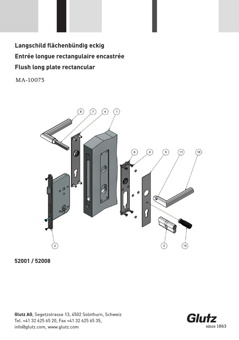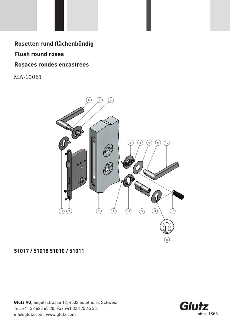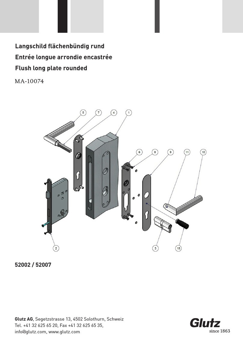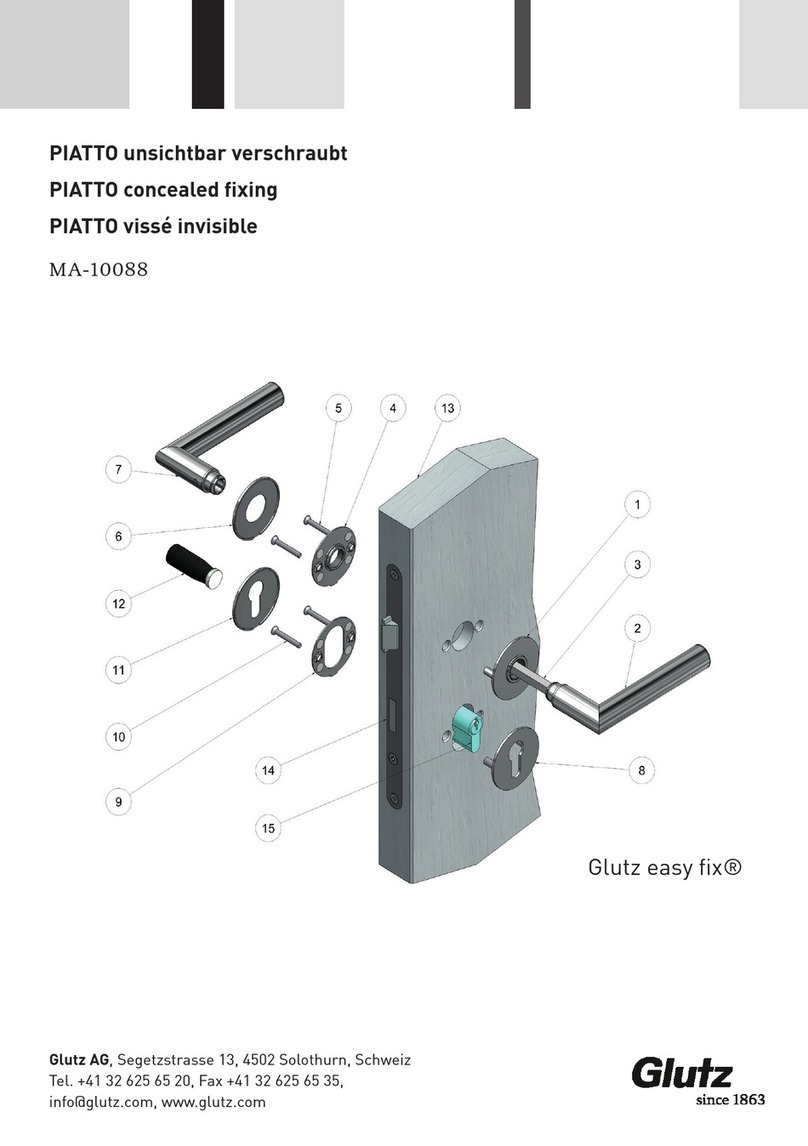
• Bohrlehre (4) und Frässchablone (3) mit dem Positionierstift auf die Schlossnuss der Türe stecken und
parallel ausrichten.
• Frässchablone mit 2 Schraubzwingen auf der Türe (1) befestigen.
• 2 Bohrungen, falls nicht vorhanden, für die 2 Schrauben (6) bohren (Abst. 63 od. 80)
• Bohrlehre entfernen und mit Oberfräse die Ausfräsung (2) für das Federelement herstellen.
Führungsring: Ø 24 mm Fräser: Ø 10 mm Frästiefe: min. 8.5mm
• Die Deckplatte (7) um 90° drehen. Den kpl. HST-PSK-Griff (8) ohne grosse Krafteinwirkung in
Schlossnuss führen. 4-Kt. Grösse kontrollieren!
• Den HST-PSK-Griff mit den beiden Schrauben (6) auf der Türe (1) festschrauben.
• Die Deckplatte (7) um 90° drehen und auf die Grundplatte aufclipsen.
• Demontage: Demontagemagnet (9) auf die Deckplatte (7) positionieren. Deckplatte (7) mit Demonta-
gemagnet abziehen. Anschliessend die Garnitur (8) demontieren.
Montageanleitung
Fixing instructions
• Insert the drilling template (4) and routing template (3) with the positioning pin into the lock
follower of the door and align it parallel.
• Fix the routing template on the door (1) with 2 screw clamps.
• If not available yet, drill 2 holes (distance 63 or 80) for the 2 screws (6).
• Remove drilling template and produce the countersink (2) for the spring element with a top mil-
ling head. Guide ring: Ø 24 mm Milling cutter: Ø 10 mm Milling depth: min. 8.5 mm
• Turn the cover plate (7) by 90°. Insert the complete HST-PSK handle (8) into the lock follower
without higher force. Check the 4-squaresize!
• Screw tight the HST-PSK handle on the door (1) with the two screws (6).
• Turn the cover plate (7) by 90° and snap it on the base plate.
• Dismantling: Place dismantling magnet (9) on the cover plate (7). Remove cover plate (7) with
dismantling magnet. Subsequently dismantle the set (8)
Glutz AG, Segetzstrasse 13, 4502 Solothurn, Schweiz
Tel. +41 32 625 65 20, Fax +41 32 625 65 35,


