Glutz Home Biometrics User manual

1
Glutz Home Biometrics
Instruction manual

2
Dear customer
Thank you for your interest in the Glutz Home
Biometrics electronic access control system.
Read this instruction manual carefully to
ensure optimal use of Glutz Home Biometrics.
In case of enquiries, please contact your
specialist dealer or contact the manufacturer
directly.
IMPRINT
Version: Instruction manual
Home Biometrics
Index: MA-10121
Article number Art. no. 272101(DE)
Art. no. 272348(FR)
Art. no. 272349(EN)
Release date: 2017-06-28
Reviewed: Product Management Glutz AG
Feedback: inf[email protected]
Status: APPROVED
Original language: German

3
Table of Contents
1 GENERAL INFORMATION 4
1.1 Target group 4
1.2 Intended use 4
1.3 Assembly instructions 4
1.4 Danger notices 5
1.5 Abbreviations and terminology 6
1.6 Symbols 6
2 SAFETY INFORMATION 7
2.1 Security from manipulation 7
3 PRODUCT DESCRIPTION 8
3.1 System overview 8
3.2 Intended use 8
and area of application
4 SYSTEM COMPONENTS 9
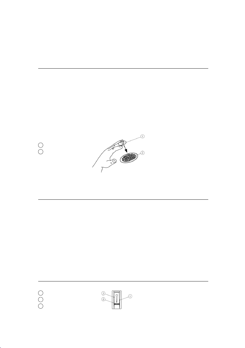
4.1 Finger scanner 9
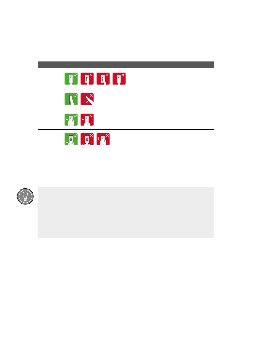
4.2 Correct execution of the 10
operator actions on the finger scanner
4.3 Optical signals on the finger scanner 12
4.4 Finger scanner technical data 12
4.5 Control units 13
4.6 Optical signals of the control units 14
4.7 Control unit technical data 14
5 INSTALLATION AND COMMISSIONING 15
5.1 Commissioning devices 15
5.2 Test of wiring 17
6 OPERATIONAL CONCEPT 18
7 ESTABLISHING NORMAL 18
OPERATION AND USE OF THE
FINGER SCANNER WITH APP
7.1 Downloading the app 19
7.2 Pairing with a mobile device 19
for the first time
7.3 Deactivating Bluetooth 20
7.4 Pairing additional mobile devices 20
7.5 Managing multiple Bluetooth finger scanners 21
7.6 Storing the user pairing code 22
7.7 Resetting the app security code 23
7.8 Protecting the system in case a 24
mobile device is lost
7.9 Opening the door 25
8 ESTABLISHING NORMAL 26
OPERATION AND USE OF THE
FINGER SCANNER WITH ADMIN FINGER
8.1 Storing the admin finger and 27
establishing normal operation
8.2 Storing a user finger 28
8.3 Storing an RFID transponder 29
8.4 Opening the door 30
8.5 Deleting a user finger 31
8.6 Deleting an RFID transponder 32
8.7 Deleting all users and 33
RFID transponders
9 RESETTING THE SYSTEM TO 34
FACTORY SETTINGS
9.1 About the finger scanner 35
9.2 About the control unit 36
9.3 About the digital input 36
9.4 About the app 37
10 UPDATING THE SOFTWARE 38
11 ERROR DISPLAYS AND TROUBLESHOOTING 38
FOR THE FINGER SCANNER
12 MAINTENANCE 39
13 DECLARATION OF CONFORMITY 39
14 DISPOSAL 39

4
1. General information
1.1 Target group
This document is intended for persons who:
• commission the system
(electrical installers, specialist personnel, etc.)
• maintain and manage the system
(owners, administrators, technicians, etc.)
This instruction manual only describes the commissioning of the Glutz
Home Biometrics devices. For information about the operation of eAccess devices
and/or the eAccess desktop software, please refer to the appropriate manuals.
1.2 Intended use
Your Glutz Home Biometrics system is an access system and must only be used
for the purpose intended by the manufacturer, the unlocking and locking of doors.
Any other use is considered as improper.
The Glutz Home Biometrics system is designed for specific areas of
application (permissible environmental conditions are described in the
chapter Technical data).
1.3 Assembly instructions
Assembly of devices
The assembly of the devices must be carried out by a qualified expert.
The assembly instructions are included in the scope of delivery.

5
1.4 Danger notices
Danger to persons
WARNING
Potentially imminent danger
Identifies a potentially threatening danger that
can lead to severe bodily injuries or death.
CAUTION
Potential danger
Identifies a potentially threatening danger that
can lead to minor bodily injuries.
Danger to property
NOTE
Damage to the product
Identifies a situation in which disregard of instructions can
damage the device or impair device function.
NOTE
Information for use that helps optimise use of the device and improve
operation of the device.
Tips and tricks for daily use.

6
1.5 Abbreviations and terminology
SM Surface-Mounted
BT Bluetooth
FAR False Acceptance Rate
FRR False Rejection Rate
FS Finger Scanner
RFID Radio Frequency IDentification
CU Control Unit
FM Flush-Mounted
1.6 Symbols
1. Step-by-step instructions
References to other sections of this manual
References to the assembly instructions
References to the connection diagram
• Lists without a specified sequence, 1st level

7
2. Safety instructions
WARNING
Life-threatening danger due to electricity
All Glutz Home Biometrics devices must be operated with safety
extra-low voltage. Only use the power supply units provided by
Glutz AG.
Disregarding this instruction entails life-threatening danger due
to electric shock.
The electrical connection must be carried out by qualified electricians only!
2.1 Security from manipulation
Install the control unit in a secure place inside the door.
In doing so, manipulation from outside is avoided.

8
3. Product description
3.1 System overview
3.2 Intended use and area of application
This product is an access system with biometric or mental identification features (finger
scan or PIN). The system consists of a detection unit and a control unit. It is available in
different models and component combinations.
The biometric access system detects the features (minutiae) of the finger lines, compares
it with the biometric information stored from the reference fingerprint and opens the
door if it matches. A model variant enables identification of the user and the opening of
the door by means of an RFID transponder.
Combination set (for Glutz eAccess control)
A Finger scanner
B2 eAccess mini control unit, plug-in power supply
B3 Mini control unit, top-hat rail power supply
C1 MINT SV mechanical multipoint lock
D Security plate with half cylinder for ingress
F3 Finger scanner to mini control unit cable
Comfort set (for Glutz MINT SVM motorised lock)
A Finger scanner
B4 Mini control unit 1 relay
C2 MINT SVM motorised multipoint lock
F3 Finger scanner to mini control unit cable
F4 Adapter cable for MINT SVM
E Lead cover with connecting cable
Comfort set (for Glutz MINT SVM motorised lock)
A Finger scanner
B1 Micro control unit
C2 MINT SVM motorised multipoint lock
F1 Finger scanner to micro control unit cable
F2 Finger scanner to micro control unit Y-cable
E Lead cover with connecting cable
G 24A/230V power supply unit
230V
A
B1 G
F1
F2
C2
E
A
B4
F3
F4
C2
E
230V
A
B 2|3
F3
C1
D
230V
Combination set
Comfort set
Compact set

9
4. System components
4.1 Finger scanner
The finger scanner detects the fingerprint with a line sensor and evaluates it.
It compares the result with the biometric information stored from the reference
fingerprint and opens the door if it matches.
The finger scanner only works correctly and reliably with the papillary grooves
of the front phalanx. Calmly draw your finger over the sensor evenly
and in the correct position.
The model variants with RFID function detect and identify
RFID transponders.
Operator actions of the finger scanner
• Draw your finger
Draw your finger downwards over the sensor evenly
• Finger touch
Briefly touch the sensor with your finger
• Hold up an RFID transponder
Operate the finger scanner with an RFID transponder
1Front phalanx
2Fingerprint
1Right guide edge
2Sensor
3Left guide edge
Finger guide

10
Action Description
1. Holding your finger straight, place it in
the centre between the guide edges.
Do not twist it.
2. Place the joint of the front phalanx
directly on the sensor.
Place your finger flatly on the finger guide.
3. Extend the adjacent fingers.
4. Move your finger downwards over the sensor
evenly. Move the entire hand with the finger.
Draw the front phalanx over the entire
sensor
in order to achieve optimal results.
The motion takes about 1 second.
4.2 Correct execution of the operator actions on the finger scanner
Draw your finger
• The index, middle and ring fingers work best.
The fingerprints of the thumb and little finger are more difficult to evaluate.
• If your fingers are often damp, they should be scanned when damp.
• Depending on their development, children's fingers do not work until
the child is about 7 years old.

11
Action Description
Touch the sensor briefly
and quickly with your finger.
Action Description
Position the surface of the RFID transponder
about 1–5 cm in front of the finger guide of the
finger scanner.
Finger touch
Hold up an RFID transponder
The 'Hold up an RFID transponder' operating mode
is only possible with finger scanners with RFID function.
Attention: only UID operation is possible ISO 14443A

12
4.4 Finger scanner technical data
4.3 Optical signals on the finger scanner
There are 2 types of LEDs:
• Status LED for the operating status
• Function LED for the function of the overall system
Optical signals on the finger scanner
1Status LED
2Function LEDs
Designation Unit Values
Power supply VDC 8–24
Power input W Heating off: 1
Heating on: 4
Temperature range °C -25 to +70
Memory Finger
RFID transponder
99
99 (only with FS with RFID
function)
Security FAR
FRR
1:10,000,000
1:100
Protection rating IP SM, IN: 54 (front side)
FM: 44 (with FM frame)
Reaction speed S 1-2
Service life Finger scans about 10 million
RFID
(only with finger scanner
RFID function)
Interface
Transponder type
ISO14443A
MIFARE Desfire EV1 with at least
1kByte memory Tested media:
Glutz G-Line Clip, Glutz G-Line
Card, Glutz C-Line Clip (other
media with ISO 14443A also
possible, but must be tested first)

13
4.5 Control units
The control units are available in 3 versions.
They can only operate one detection unit per control unit.
Each detection unit operates with each control unit.
Function of the control unit
The control unit is the actuator unit of the system.
The control unit switches a relay and provides a digital input.
With the variant with eAccess, a signal is transmitted wirelessly
to the paired eAccess fitting.
Operator actions of the control units
Product name Figure Application
82730
Micro control unit
1 relay
Activation of a
motorised lock
Integration in the door leaf
82740
eAccess mini
control unit
Activation of an eAccess
device by pairing
plug-in power supply
82741
eAccess mini
control unit
Activation of an eAccess
device by pairing
top-hat rail power supply
82745
Mini control unit
1 relay
Activation of a
motorised lock
Product name Campaign Function
82740
82741
82745
Press the button for about 4 sec Reset to factory settings
82730 Press the button for about 4 sec Reset to factory settings

14
4.6 Optical signals of the control units
4.7 Control unit technical data
82740 / 82741 / 82745 Mini control unit 1 relay
82730 Micro control unit 1 relay
Designation Unit Values
82740/82741/82745
Mini control unit
82730
Micro control unit
Power supply VDC 8–24 8–24
Power input W approx. 1 approx. 1
Relay Quantity 1 1
Switching power
Relay
VAC/A
VDC/A
42/2 42/2
Temperature range °C -20 to +70 -25 to +60
Protection rating IP 20 20
Digital inputs
(only potential-free
contact can be connected)
Quantity 1 1
The upper status LED indicates wheth-
er the control unit is coupled with the
finger scanner. The lower status LED
indicates that a relay switches.
The LED indicates whether the control
unit is coupled to the finger scanner
and whether the relay switches.

15
Description Display
1. Secure the
assembly status
of the devices.
Close the
covers.
2. Connect the
power supply
unit to the mains
voltage.
The upper status LED of the mini
control unit 1 relay blinks orange/green
alternatingly and/or the LED of the
micro control unit 1 relay
slowly blinks green: factory setting.
3. No
Action
required
Status LED of
the finger scanner
blinks blue
5. Installation and commissioning
5.1 Commissioning devices
1. Variants: With control unit 82745 or 82730
Assemble and wire the product correctly before connecting the
power supply. Failure to do so entails the risk of potential property damage!
Do not connect the power supply yet!
Assemble the system according to the supplied assembly instructions.
Wire the system according to the supplied wiring plan.

16
The pairing can take place by means of card programming
or software programming:
1. Card programming: See 'eAccess operating manual
Card programming', available at www.glutz.com
2. Software programming: Both devices must be at the same access point
see 'eAccess operating manual',
available at www.glutz.com
2. Variants: With control unit 82740 or 82741
With use of control unit 82740 / 82741 in combination with an eAccess
fitting, the control unit must be paired with the fitting.
Description Display
1. Secure the
assembly status
of the devices.
Close the
covers.
2. Connect the
power supply
unit to the mains
voltage.
The upper status LED of the mini control
unit 1 relay blinks orange/green alternatingly
and/or the LED of the micro control unit 1 relay
slowly blinks green: factory setting.
3. No
Action
required
Status LED of
the finger scanner
blinks blue
4. Pairing of eAccess
fitting and control
unit 82740 / 82741
The fitting LED
illuminates green

17
Action Description Display
1. Place a finger
on the sensor and leave it
in place for more than 3 s.
Status LED blinks blue
2. Remove your finger
from the sensor within
the next 2 s.
The status LED of the finger
scanner illuminates green.
The upper status LED of the
mini control unit 1 relay illuminates
green and/or the LED of the micro control unit
1 relay slowly blinks green.
5.2 Test of wiring
You can check the wiring using test mode.
Executing test mode
A test can only take place if an admin finger has
not been stored and/or no mobile device is paired.
Connect the mains voltage and perform the test within the next
10 minutes. If the 10 minutes have expired, this test
is possible after the mains voltage is connected again.
You must place your finger on the sensor for a maximum of 5 s.
If you leave your finger on the sensor longer, the relay does not switch.
The relay switches.

18
6. Operational Concept
Depending on the detection unit, there are different
operating concepts available:
• Open Biometric App – administration of the Bluetooth finger scanner
with a mobile device
• Admin finger – administration of the finger scanner with admin finger
Browse to the operating concept of your detection unit!
See chapter 7 'Establishing normal operation and
use of the finger scanner with app'
See chapter 8 'Establishing normal operation and
use of the finger scanner with admin finger'
7. Establishing normal
operation and use of the finger
scanner with app
You must commission the devices before you begin
with the administration of your system.
See 5.1 'Test of wiring'
The finger scanner is ready for the paring of the Bluetooth finger scanner with the
mobile device. The Open Biometric app is used to program the system. Doors can
also be opened with the app.

19
7.2 Pairing with a mobile device for the first time
You need a security code to pair a device.
The factory admin pairing code or app security code is 9999.
For security purposes, you must change the admin pairing code to a 6-digit
admin pairing code the first time the system is paired. Make note of this code,
because it is needed to pair additional mobile devices.
The pairing between the finger scanner and mobile device has been carried out. The
system is in normal operation. Now you can begin with the
programming and administration of the finger scan access system.
Now you only need the intuitive smartphone app for administration of your
Bluetooth finger scanner. Tap on the desired
functions in the app and follow the instructions on the display.
Description Display
1. Start the Open Biometric App.
2. According to the instructions on the display:
Pair the mobile device with the
finger scanner and use the factory admin
pairing code 9999 .
The status LED illuminates blue,
the left function LED illuminates
orange.
7.1 Downloading the app
The app is available for Apple iOS and Google Android.
Download the app from App Store or Google Play.
Enter the search term 'Open Biometric'.

20
7.3 Deactivating Bluetooth
You can deactivate the Bluetooth functionality (factory setting: active).
The pairing between the finger scanner and mobile device has been carried out.
Now you can begin with the programming and administration of the finger scan
access system via app.
With this setting, Bluetooth on the finger scanner is deactivated
after 15 minutes in one of the following cases:
• No mobile device was paired
• No finger was stored
You can re-activate Bluetooth in the admin finger menu.
7.4 Pairing additional mobile devices
You can pair additional mobile devices with the Bluetooth finger scanner with your
chosen 6-digit admin or user pairing code.
Instructions
1. Start the Open Biometric App.
2. Select Administration.
3. Select System status.
4. Activate under Bluetooth Settings
Deactivate BT on finger scanner after 15 minutes of inactivity.
Description Display
1. Start the Glutz Open
Biometric App.
2. According to the instructions on the display:
Pair the mobile device with the
finger scanner and use your chosen
6-digit admin and/or user
pairing code.
The status LED illuminates blue,
the left function LED illuminates
orange.
Table of contents
Other Glutz Door Lock manuals