Goot RX-822AS User manual

PB
1
TAIYO ELECTRIC IND.CO.,LTD.
TEMPERATURE CONTROLLED
LEAD-FREE DUAL PORT SOLDERING STATION
RX-822AS
Thank you for buying a goot soldering station. Your new soldering station has been engi-
neered and manufactured to goot's high standards of dependability, ease of operation, and
operator safety. If you follow the instructions and safety precautions in this manual and use
the soldering station properly and only for what it is intended, you will enjoy years of safe,
reliable service. Thank you again for buying a goot soldering station.
WARNING
Before using the soldering station, read the Operation Manual.
Failure to follow the safety precautions and instructions in this
manual could result in serious injury and property damage.
OPERATION MANUAL
KEEP THIS MANUAL FOR FUTURE REFERENCE
TAIYO ELECTRIC IND.CO.,LTD.
Note Tips Not Included.
Tips Sold Separately.
Soldering Iron Stand x 2 included.

TAIYO ELECTRIC IND.CO.,LTD.
2
TAIYO ELECTRIC IND.CO.,LTD.
WARNING
Failure to obey a safety warning could result in serious
injury or death to yourself or to others. Always follow the
safety precautions to reduce the risk of electric shock, fire
or personal injury.
CAUTION
Failure to obey a safety caution may result in a minor or
moderate injury to yourself or to others. Always follow the
safety precautions to reduce the risk of electric shock, fire
or personal injury.
Safety Mark Definitions
Follow all WARNINGS and CAUTIONS in this manual for the safe and correct
use of the soldering station and to protect the operator and others from injury
and damage to property. Please make sure you fully understand all parts of this
manual.

TAIYO ELECTRIC IND.CO.,LTD.
2TAIYO ELECTRIC IND.CO.,LTD.
3
1Table of Contents
1. Table of Contents / Specifications ..................................................3
2. Introduction ...............................................................................5
2.1 Features of the RX-822AS..............................................................
5
2.2 Unpacking ...............................................................................6
2.3 Name of Parts ...............................................................................7
2.4 Setup ...............................................................................9
3. Rules for Safe Operation .................................................................10
4. Operation Instructions.....................................................................12
4.1 General Control Panel Operation Flow chart..............................12
4.2 Changing the Set Temperature ....................................................13
4.3 Calibration of the Tip Temperature ..............................................14
4.4 Calibration Function......................................................................15
4.5 Sleep Function .............................................................................16
Setting the Sleep Temperature (SST) .......................................16
Setting the Sleep Start Time (CT) .............................................17
Setting the Sleep Sensitivity(DIF) .............................................18
4.6 Setting the Shutdown Function....................................................19
4.7 Setting the Temperature Range for the Alarm ............................20
4.8 Control Function for Overshooting ..............................................21
4.9 Setting the Alarm Sound ..............................................................22
4.10 Setting the Temperature Scale Display ......................................23
4.11 Key Lock Function........................................................................24
Setting and Releasing the Key Lock.........................................24
Changing the Code Number......................................................25
Resetting the Code Number......................................................26
4.12 How to Restore Default Setting .................................................27
5. Maintenance .............................................................................28
5.1 How to Change the Tip .................................................................28
5.2 How to Change the Grip Rubber ..................................................29
5.3 How to Change the Fuse ..............................................................29
5.4 Housing Cleaning..........................................................................30
5.5 How to Use and Maintain a Lead-Free Soldering Iron ...............30
6. Troubleshooting .............................................................................31
7. Replacement Tips .............................................................................32
8. Replacement Parts ..........................................................................34
9. Parameters .............................................................................35

TAIYO ELECTRIC IND.CO.,LTD.
4
TAIYO ELECTRIC IND.CO.,LTD.
MODEL RX-822AS
Voltage 110-120, 220-240V AC
Power Consumption 220–260W
Soldering Iron
Voltage /Wattage
RX-85GAS: Soldering unit [1] side 24V AC / 150W
RX-80GAS: Soldering unit [2] side 24V AC / 72W
Temperature Setting Range 50–450°C (122–842°F)
Dimensions
Control Unit 194(L) X 116(W) X 105(H)mm
RX-85GAS: Soldering unit [1] side 174mm (with RX-85HRT-5D, w/o cord bushing)
RX-80GAS: Soldering unit [2] side 158mm (with RX-80HRT-B, w/o cord bushing)
Weight
Control Unit Approx. 4.9kg (w/o cord)
RX-85GAS: Soldering unit [1] side Approx.39g (with RX-85HRT-5D, w/o cord bushing)
RX-80GAS: Soldering unit [2] side Approx. 28g (with RX-80HRT-B, w/o cord bushing)
Control Unit to Soldering Unit Cord Length RX-85GAS : 1.5m, RX-80GAS : 1.2m
AC Power Cord Length 1.5m 3 core cord (ground plug)
Leak Voltage Less than 2mV
Ground Resistance Less than 2Ω
Accessories Soldering Iron Stand (ST-21) X 2
Specifications

TAIYO ELECTRIC IND.CO.,LTD.
4TAIYO ELECTRIC IND.CO.,LTD.
5
2Introduction
1. 2 soldering irons can be used
Can be prepared with 2 different tip types.
Therefore, you can do different types of
work at the same time.
2. 150W and 72W soldering irons can be used
simultaneously
Port [1] can be used for the 150W or 72W.
Port [2] can be used for 72W only. You can-
not use 150W in both parts.
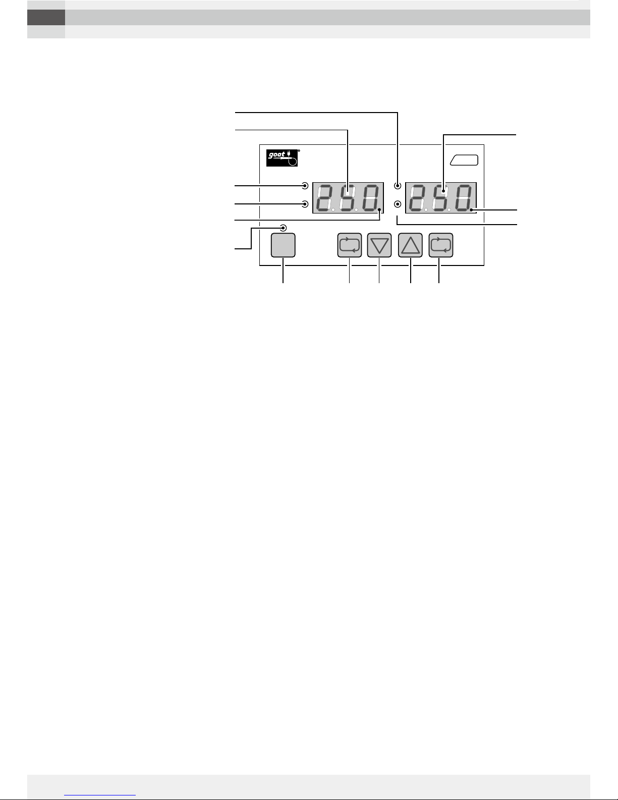
3. The 2 soldering irons can be set to different
temperatures.
Port [1] and [2] can be set to different tem-
peratures. The set temperature and condi-
tion can be checked easily with the sepa-
rate temperature display.
4. Excellent heat recovery
Achieved by combining a compact-high-
output heater with a high-sensitivity-sensor.
It makes difficult work that requires high
heat capacity, easy.
5. New ergonomic design soldering unit (PAT.)
Provides comfortable handling, flexible sol-
dering unit cord and a shorter distance from
the grip to the tip.
6. Fastest in its class
Reaches 350˚C (662˚F) in approx. 6 sec-
onds. (Equipped RX-80HRT series )
7. Easy to replace tip without using tools (PAT.)
Slide-change tip. No tools or heat resis-
tance pads needed.
8. Wide variety tip
9 tips for the RX-85HRT series and 7 tips
for the RX-85HSRT series are available. A
total of 43 tips with different shapes includ-
ing the tips for the RX-80HRT series are
available.
9.
Thick iron plating for lead-free soldering
All tips have a thick iron plating to slow ero-
sion caused by lead-free soldering.
10. Key Lock function (PAT.)
Tamper-proof keypad lock using a pass-
word. No tools or cards are needed.
11. Sleep function (PAT.)
The control unit automatically lowers the
temperature when inactive for a preset peri-
od of time, preventing overheating. Time
and temperature can be preset when inac-
tive. Can be used with the shut down func-
tion.
12. Sleep function release (PAT.)
Sleep mode can be exited by touching the
wet sponge to cause temperature fluctua-
tion.
13. Calibration function (PAT.)
The calibration function digitally offsets the
difference between the tip temperature and
the tip thermometer temperature.
14. Shutdown function
When the unit is not used for a preset time,
the unit enters shutdown mode automati-
cally, to prevent any unexpected accidents.
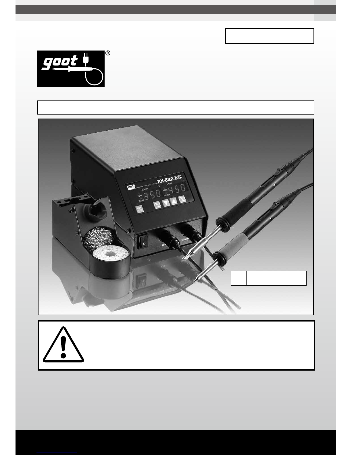
2-1 Features of the RX-822AS
The RX-822AS includes 2 soldering units per one control unit for lead-free soldering. The
tip is a long-life compact type with integrated heater.

TAIYO ELECTRIC IND.CO.,LTD.
6
TAIYO ELECTRIC IND.CO.,LTD.
Packing List
■Control Unit
■Soldering Unit (RX-85GAS, RX-80GAS)
■ Soldering Iron Stand ST-21 x 2
■ Power Cord
■ Operation Manual
Please make sure that all the items listed below are included, and that the soldering station
functions properly before throwing away the packaging.
2-2 Unpacking
RX-822AS
INSTRUCTION MANUAL
KEY
LOCK
RX-822
HEAT
SLEEP
1.TEMP. ˚C
AS
HEAT
SLEEP
2.TEMP. ˚C
DUAL PORT SOLDERING STATION
21
Operation Manual
Soldering
Iron Stand
ST-21
Control Unit
Power Cord
Soldering Unit
RX-80GAS Soldering Unit
RX-85GAS

TAIYO ELECTRIC IND.CO.,LTD.
6TAIYO ELECTRIC IND.CO.,LTD.
7
Tip (Sold separately)
Rib to prevent inserting in the
RX-80GAS soldering unit
Check the direction of the
tip before inserting.
1
0
KEY
LOCK
RX-822
HEAT
SLEEP
1.TEMP. ˚C
AS
HEAT
SLEEP
2.TEMP. ˚C
DUAL PORT SOLDERING STATION
2 1
Operation Panel
Slide Lever
Grip Rubber
Adapter Ring
Soldering Unit
Connector
Power Cord Socket
(With built-in replacement fuse)
Power Switch
Output Terminal for
Soldering unit [2](72W)
Output Terminal for
Soldering unit [1] (150W/72W)
(Applicable Tip : RX-85HRT/85HSRT)
Control Unit
Soldering Unit
2-3 Name of Parts

TAIYO ELECTRIC IND.CO.,LTD.
8
TAIYO ELECTRIC IND.CO.,LTD.
KEY
LOCK
RX-822
HEAT
SLEEP
1.TEMP. ˚C
AS
HEAT
SLEEP
2.TEMP. ˚C
①
①
⑥
③
②
②
④
④
⑤
⑦ ⑦⑧ ⑨
DUAL PORT SOLDERING STATION
2 1
③
1. HEAT lamp
Lights up when the heater is ON.
2. SLEEP lamp
Flashes while setting the SLEEP function. The flashing will get faster 30
seconds before going into SLEEP mode. Lights up when the unit enters
SLEEP mode.
3. TEMP. display
When the power is turned ON or when SLEEP mode is exited, the TEMP
display shows the tip temperature rise to the set temperature. The TEMP
display shows the set temperature when it is reached.
4. ALARM lamp (to the right of the last digit in the temperature display)
Flashes when the tip temperature is within the DIF range.
Turns off when the tip temperature is out of the DIF range.
Flashes when the tip temperature is out of the upper and lower tempera-
ture limits.
5. KEY LOCK lamp
Flashes while setting the Key Lock function.
Flashes when the unit is in Key Lock mode.
6. KEY LOCK key
Use to set the Key Lock function.
Use to lock and unlock the keypad.
7. SETTING key
This key is used to set the temperature and parameters.
8. DOWN key
This key is used to reduce the temperature and change the parameter.
9. UP key
This key is used to increase the temperature and change the parameter.
■Operation Panel

TAIYO ELECTRIC IND.CO.,LTD.
8TAIYO ELECTRIC IND.CO.,LTD.
9
Assemble according to following illustrations. Parts cannot be connected other than as shown.
Connecting parts by force will result in breakage.
2-4 Setup
Soldering unit
RX-80GAS[72W]
Soldering unit
RX-85GAS/RX-80GAS[150W/72W]
RX-80HRT Series
(Sold separately)
[72W integrated heater]
RX-85HRT/RX-85HSRT Series
(Sold separately)
[150W high power integrated heater]
Output Terminal for
Soldering unit [2] (72W)
Output Terminal for
Soldering unit [1] (150W/72W)
KEY
LOCK
RX-822
HEAT
SLEEP
1.TEMP. ˚C
AS
HEAT
SLEEP
2.TEMP. ˚C
DUAL PORT SOLDERING STATION
21

TAIYO ELECTRIC IND.CO.,LTD.
10
TAIYO ELECTRIC IND.CO.,LTD.
3Rules for Safe Operation
1. KNOW YOUR SOLDERING STATION.
Do not attempt to operate this soldering station until you have read thoroughly and
understood completely all instructions, safety, rules, etc. contained in this manual.
Failure to comply may result in accidents involving fire or serious personal injury.
2. DO NOT USE IN DANGEROUS ENVIRONMENTS.
Do not use the soldering station in damp or wet locations or expose it to external envi-
ronmental conditions, particularly rain. Never use it in an explosive atmosphere. The
heat from the heater can ignite fumes. Be sure that the work area is properly lit and
well ventilated.
3. KEEP CHILDREN AND BYSTANDERS AWAY FROM THE SOLDERING STATION.
Do not let bystanders touch the soldering station. All bystanders should be kept a safe
distance from the work area.
4. PROPERLY STORE THE SOLDERING STATION WHEN NOT IN USE.
When not in use, the soldering station should be stored in a dry and locked place.
Keep out of the reach of children.
5. USE FOR THE RIGHT JOB.
This soldering station is an electrical tool used to solder parts and melt solder. Do not
use the soldering station for any other purpose. For example: The soldering station
should never be used to warm water or other liquids.
6. WEAR PROPER APPAREL, SAFETY GLASSES, GLOVES AND MASK.
Do not wear loose clothing (such as a necktie). Tie up long hair. Clothing or hair can
burn on contact with the tip or surrounding heated parts.
7. CONNECT TO THE SPECIFIED AC POWER SUPPLY.
The power voltage for this soldering station is indicated at the back of the con-
trol unit. Never plug the soldering station into any other voltage.
8. DO NOT ABUSE THE POWER CORD AND INSPECT IT PERIODICALLY.
Never pull the power cord to disconnect it from the receptacle. Keep the power cord
away from heat, oil and sharp edges. If it is damaged, contact the nearest distributor
for a replacement.
WARNING
Do not operate the soldering station until you have read
and understood the whole manual and safety instruc-
tions.

TAIYO ELECTRIC IND.CO.,LTD.
10 TAIYO ELECTRIC IND.CO.,LTD.
11
WARNING
The RX-822AS is an anti-static model. Be sure to prop-
erly ground the soldering station using a grounded
receptacle to prevent electric shocks and anti-static. If
it is not properly grounded, electric shocks will occur.
As the soldering station uses conductive materials,
please be careful not to touch any electrical power
source or a serious injury will result.
9. USE STAND PROVIDED.
Be sure to use the soldering iron stand (ST-21) included with the soldering station. If
this stand is not used, the plastic parts (adapter ring and/or soldering unit housing) of
the soldering iron unit could become damaged. Position the soldering iron stand on a
flat work-surface bench. Follow instructions included with the soldering iron stand to
assemble it.
10.CONCERNING THE TIP.
Allow the tip to cool naturally. Never use any other method to cool it down. For example:
Water should never be poured or sprinkled on the tip to cool it down.
11.The soldering iron is not intended for use by young children or infirm persons
without supervision. Young children should be supervised to ensure that they do
not play with the soldering iron.

TAIYO ELECTRIC IND.CO.,LTD.
12
TAIYO ELECTRIC IND.CO.,LTD.
Note: If nothing is pressed for 30 seconds during setting the temperature/ parameters,
the temperature / parameter display will record the new data, and the display will return
to the normal conditions. If nothing is pressed for 30 seconds during setting / changing
the code number, the code number will return to the prior settings.
TURN THE POWER ON
OPERATION MODE
Changing the
Set Temperature
4-2
Key Lock
Function
4-11
Changing the Parameter
SETTING key SETTING key KEY LOCK key
KEY
LOCK
tPN Calibration of the Tip Temperature 4-3
cAL Calibration Function 4-4
SSt Sleep Temperature 4-5
ct Sleep Start Time 4-5
dIF Sleep Sensitivity 4-5
SUt Shutdown Start Time 4-6
HAlarm for Upper Temperature Limit
4-7
LAlarm for Lower Temperature Limit
4-7
td Overshooting Control 4-8
bUZ Alarm Sound 4-9
c–F Temperature Scale Display 4-10
Press down
for over 3
seconds
4Operating Instructions
4-1 General Control Panel Operation Flow Chart
When the power is switched on the tip will start heating up.
Press the key for the temperature setting mode. Press down the key for over 3
seconds for the parameter changing mode. Press the key for the key lock function
setting / changing mode.

TAIYO ELECTRIC IND.CO.,LTD.
12 TAIYO ELECTRIC IND.CO.,LTD.
13
1
2
3
Example: Changing the temperature from 250°C (482°F) to 340°C (644°F).
Press the [SET.] key of
soldering unit you desire.
Press and hold the [UP]
key to select 340.
At the time of shipping the temperature is set at 250°C (482°F). The temperature can
be set from 50°C (122°F) to 450°C (842°F). *The tip temperature will not become lower
than ambient temperature.
*For the steps given in the operation instructions, only °C is used.
Key Operation TEMP Display
Press the [SET.]key
of soldering unit you
changed.
Note: If nothing is pressed for 30 seconds during setting the tempera-
ture, the temperature display will record the new data and the
display will return to the normal conditions.
*The set temperature should be set at 50°C (90˚F) higher than the
sleep temperature (see the section 4-5), otherwise you will not be
able to set the set temperature value.
(Example: If the set temperature is set at 200°C (392˚F), the sleep
temperature must be 150°C (302˚F) or lower.
4-2
Changing the Set Temperature
(Each soldering unit can be set separately)
21
or
Displays flashes
Setting completed

TAIYO ELECTRIC IND.CO.,LTD.
14
TAIYO ELECTRIC IND.CO.,LTD.
1
2
3
How to set the TIP No.
Press the [UP] key
to select [2].
The above tip number (TIP NO.) may be changed without notice, due to design changes, etc.
Be sure to check the actual engraved tip number of your tip (at the base).
Key Operation TEMP Display
Press down the [SET.] key of
soldering unit you changed for
over 3 seconds.
Example: When changing the tip used from tip number 1to tip number 2
Tip No. List (RX-85HRT Series )
Tip No. List (RX-85HSRT Series )
MODEL TIP
NO.
RX-80HRT-0.8D 0
RX-80HRT-1.2D 2
RX-80HRT-1.6D 2
RX-80HRT-2.4D 1
RX-80HRT-3.2D 1
RX-80HRT-5.4D 0
RX-80HRT-3K 1
RX-80HRT-4.5K 1
RX-80HRT-4.5KH
1
RX-80HRT-5.5K 1
RX-80HRT-0.5C 3
RX-80HRT-1BC 1
RX-80HRT-2.3BC 1
MODEL TIP
NO.
RX-80HRT-SB 3
RX-80HRT-B 1
RX-80HRT-2B 1
RX-80HRT-LB 2
RX-80HRT-LBJ 2
RX-80HRT-1C 4
RX-80HRT-2C 4
RX-80HRT-3C 2
RX-80HRT-3BC 1
RX-80HRT-4C 1
RX-80HRT-BM 1
RX-80HRT-2CD 4
RX-80HRT-3CD 2
RX-80HRT-4.7C 1
MODEL TIP
NO.
RX-85HRT-B L2
RX-85HRT-2BC L1
RX-85HRT-3BC L1
RX-85HRT-5BC L1
RX-85HRT-7BC L1
MODEL TIP
NO.
RX-85HRT-3D L1
RX-85HRT-5D L1
RX-85HRT-7D L1
RX-85HRT-6K L1
MODEL TIP
NO.
RX-85HSRT-B L2
RX-85HSRT-1.6D L1
RX-85HSRT-2.4D L1
RX-85HSRT-3.2D L1
MODEL TIP
NO.
RX-85HSRT-2BC L1
RX-85HSRT-3BC L1
RX-85HSRT-4.5K L1
Tip No. List (RX-80HRT Series )
Press down the [SET.]
key of soldering unit
you desire for over 3
seconds.
21
or
The temperature of the RX-822AS can be calibrated easily by inputting the tip number, which
is engraved on the tip. When you change to a different type of tip, you will need to calibrate
the tip temperature as below.
4-3 Calibration of the Tip Temperature (Each soldering unit can be set separately)
No.1
Tip number
Returns to the set tem-
perature display.
Displays
alternately
Setting completed
Displays
alternately
Shipping default setting: 1

TAIYO ELECTRIC IND.CO.,LTD.
14 TAIYO ELECTRIC IND.CO.,LTD.
15
1
2
4
How to Calibrate the Temperature
Press the [SET.]key to
select [cAL].
Key Operation TEMP Display
Press down the [SET.] key of
soldering unit you changed for
over 3 seconds. Returns to the set temper-
ature display.
Example : Where the set temperature is 300°C (572°F),
tip thermometer value is 295°C (563°F), and
the calibration value to be input is 5°C (9°F).
3Press the [UP] key to
select [5].
Leave the CAL value at 0 if you don’t calibrate. (Shipping default setting is 0 )
4-3 Calibration of the Tip Temperature (P.14) should be done after calibration of the display.
Press down the [SET.]
key of soldering unit
you desire for over 3
seconds.
21
or
The RX-822AS can be calibrated using a tip thermometer. Generally speaking, when
measuring the tip temperature of the RX-822AS with a standard tip thermometer, the
measured temperature will usually be lower than that of the actual tip temperature
displayed on the RX-822AS control unit display. This could be because the tip is not
coming into contact properly with the sensor of the tip thermometer. It could also be
because once the tip thermometer comes into contact with the RX-822AS soldering
tip, the metallic parts in the thermometer conduct heat which transfers away from the
RX-822AS tip. This results in the thermometer indicating a slightly lower temperature
than the one in the RX-822AS display.
4-4 Calibration Function (Each soldering unit can be set separately)
Setting completed
Displays
alternately
Displays
alternately
Displays
alternately

TAIYO ELECTRIC IND.CO.,LTD.
16
TAIYO ELECTRIC IND.CO.,LTD.
The sleep start timer (CT) function automati-
cally lowers the temperature of the tip after a
preset period of inactivity. This function lowers
the tip temperature and it will be in standby
condition. It helps reduce overheating and
oxidation of the tip. The sleep function can be
used with the 4-6 shut down function.
4-5 Sleep Function (Each soldering unit can be set separately)
CT
Soldering tip temperature
SST
Set temperature
Sleep start
DIF
Operation
DIF (Sensitivity)
Power ON Time
(Sleep start time)
(Sleep setting temp.)
2
Setting the Sleep Temperature (SST) Unit: °C
While setting the sleep function, the sleep lamp will flash. The flashing will get faster 30 sec-
onds before going into sleep mode. When the soldering station has entered Sleep mode,
the sleep lamp will change from flashing to continuously lit, and the display will alternate
between “SLP” and the temperature. To use sleep function manually during operation: for
soldering unit [1] press down the [UP]
key for over 1 second and for soldering unit [2] press
down the [DOWN]key for over 1 second. (Active Sleep Function )
Key Operation TEMP Display
3Press the [DOWN]
key to set to 150.
Press the [SET.] key
to select [SST].
1
4Press down the [SET.] key of
soldering unit you changed for
over 3 seconds.
Press down the [SET.]
key of soldering unit
you desire for over 3
seconds.
21
or
Example : Changing the sleep temperature
from 200°C (392°F) to 150°C (302°F).
Displays
alternately
Displays
alternately
Displays
alternately
Setting completed
Note: Sleep mode cannot be exited by touching
the wet sponge if the sleep temperature (SST) is
set below 100 °C because there will be very little
temperature fluctuation.
How to release the sleep mode
Sleep mode can be exited by touching
the tip onto the wet sponge to cause
temperature fluctuation. Also it can be
exited by pressing any key on the control
panel.
Returns to the set
temperature display.

TAIYO ELECTRIC IND.CO.,LTD.
16 TAIYO ELECTRIC IND.CO.,LTD.
17
2Press the [SET.] key to
select [CT].
Key Operation TEMP Display
Example : Changing the sleep start
time from 5to 10 minutes.
3Press the [UP] key to
change 5 to 10.
By setting the CT (Sleep start time) to 0, the sleep function will be turned off and the
SLEEP lamp will turn off.
1
4Press down the [SET.] key of
soldering unit you changed for
over 3 seconds.
Press down the [SET.]
key of soldering unit
you desire for over 3
seconds.
(Each soldering unit can be set separately)
21
or
Setting completed
Returns to the set
temperature display.
Setting the Sleep Start
Time (CT) Unit: mins.
Displays
alternately
Displays
alternately
Displays
alternately

TAIYO ELECTRIC IND.CO.,LTD.
18
TAIYO ELECTRIC IND.CO.,LTD.
2
Key Operation TEMP Display
3Press the [UP]
key to set to 3.0
Press the [SET.]
key to select [DIF].
Note: *If the sleep sensitivity value (DIF) is set too high, there is a possibility that the
sleep function will be activated even during soldering. If this happens, reduce the
sleep sensitivity value.
*Sleep sensitivity value (DIF) can be set anywhere between 0°C (0°F) and 20°C
(36°F).
*If the sleep sensitivity value (DIF) is set too low, there is a possibility that the
sleep function will not be activated even after passing the set sleep start time. If
this happens, increase the sleep sensitive value.
1
4Press down the [SET.] key of
soldering unit you changed for
over 3 seconds.
Press down the [SET.]
key of soldering unit
you desire for over 3
seconds.
(Each soldering unit can be set separately)
21
or
Setting the Sleep
Sensitivity (DIF) Unit : °C Example : Changing the Sleep Sensitivity
value to 2°C (3.6°F) to 3.0°C (5.4°F).
Returns to the set
temperature display.
Setting completed
Displays
alternately
Displays
alternately
Displays
alternately

TAIYO ELECTRIC IND.CO.,LTD.
18 TAIYO ELECTRIC IND.CO.,LTD.
19
2
3Press the [DOWN] key
to set to 30.
Press the [SET.]
key to select [SUT].
1
4Press down the [SET.] key of
soldering unit you changed for
over 3 seconds.
Press down the [SET.]
key of soldering unit
you desire for over 3
seconds.
21
or
When the unit is not operated during the preset time, the unit automatically shuts down.
This function prevents operators forgetting to turn the power off.
4-6 Setting the Shutdown Function (Each soldering unit can be set separately)
CT SUT
DIF
Power ON Time
Soldering tip temperatrue
Operation
(Shutdown start time)
Power OFF
Sleep setting temp.
Set temperature
(Sleep start time)
DIF (Sensitivity)
When using together with Sleep function.Shutdown Function
SUT Power OFF
Soldering tip temperatrue
Set temperature
Power ON Time
Operation
DIF
DIF (Sensitivity)
(Shutdown start time)
Key Operation TEMP Display
When the SUT (Shutdown Start Time) value is set to 0, the shutdown function is OFF.
When the unit enters shutdown, Sdn and the temperature are displayed alternately.
When the temperature drops below 50°C only a dot to the right of the last digit on the
TEMP display remains lit.
To use the unit again after shutting down, turn the power switch OFF, wait a few sec-
onds, and then switch ON again.
Example : Changing the Shutdown start time from 60 to 30.
Unit : mins
Displays
alternately
Displays
alternately
Displays
alternately
Setting completed
Returns to the set
temperature display.
Setting the Shutdown
start time (SUT)

TAIYO ELECTRIC IND.CO.,LTD.
20
TAIYO ELECTRIC IND.CO.,LTD.
2Press the [SET.] key
to select [H] or [L].
3Change the preset temperature by
pressing the [UP] or [DOWN] key.
1
4Press down the [SET.] key of sol-
dering unit you changed for over 3
seconds.
Press down the [SET.]
key of soldering unit you
desire for over 3 seconds.
21
or
Setting the alarm range (H,L)
Key Operation TEMP Display
Shipping Default Setting : 50˚C (Upper / Lower)
Returns to the set
temperature display.
Setting completed
Displays
alternately
Displays
alternately
Displays
alternately
Displays
alternately
Upper Temperature Limit
Lower Temperature Limit
This function warns the operator with
an alarm, when the tip temperature
exceeds the set parameters. The diag-
onal lines in the illustration on the right
show when the alarm will sound.
Both the upper and lower limit alarms
can be set from 3˚C to 100˚C.
To turn off this function set both the
upper and lower limit to 3˚C or lower. The display will then show [---].
4-7
Setting the Temperature Range for the Alarm
(Each soldering unit can be set separately)
Lower limit temp.
Set temperature
Upper limit temp.
L H
Table of contents
Other Goot Soldering Gun manuals

Goot
Goot XST-80 User manual

Goot
Goot Anti-Static Series Instructions for use

Goot
Goot POT-50C User manual

Goot
Goot SVS-500 User manual

Goot
Goot TP-100 Instructions for use

Goot
Goot NC-100R User manual

Goot
Goot RX-892AS User manual

Goot
Goot ST-27 User manual

Goot
Goot PX-501 User manual

Goot
Goot RX-701AS Series User manual
Popular Soldering Gun manuals by other brands

Hakko Electronics
Hakko Electronics FX-888 instruction manual

Vishay Precision Group
Vishay Precision Group Micro-Measurements Mark V Operating and maintaining

Radio Shack
Radio Shack Make:it 6400254 user guide

Weller
Weller WLC200 quick start guide

jbc
jbc RBA-A user manual

Powerplus
Powerplus POWX1386 instructions