Goot POT-50C User manual

1
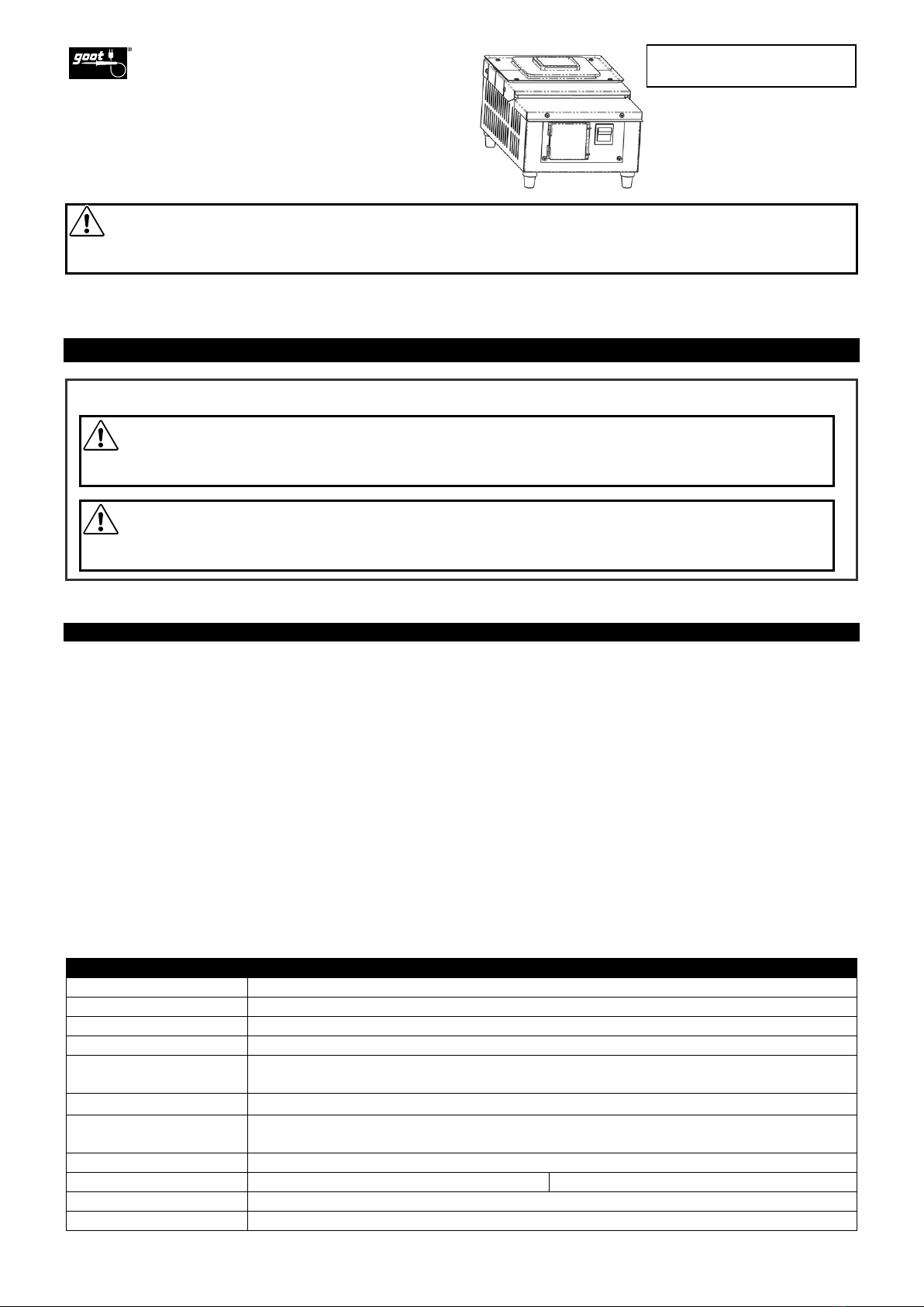
Thank you for buying a goot solder pot. Accurate PID temperature control, long life ceramic heater and solder bath material are
perfect for lead-free soldering.
KEEP THIS MANUAL FOR FUTURE REFERENCE
The safety signal words [WARNING] and [CAUTION] are defined below.
1. Table of Contents / Specifications
1. Table of Contents / Specifications...............................................................................................................................................1
2. Introduction.................................................................................................................................................................................1
2.1 Features ...............................................................................................................................................................................1
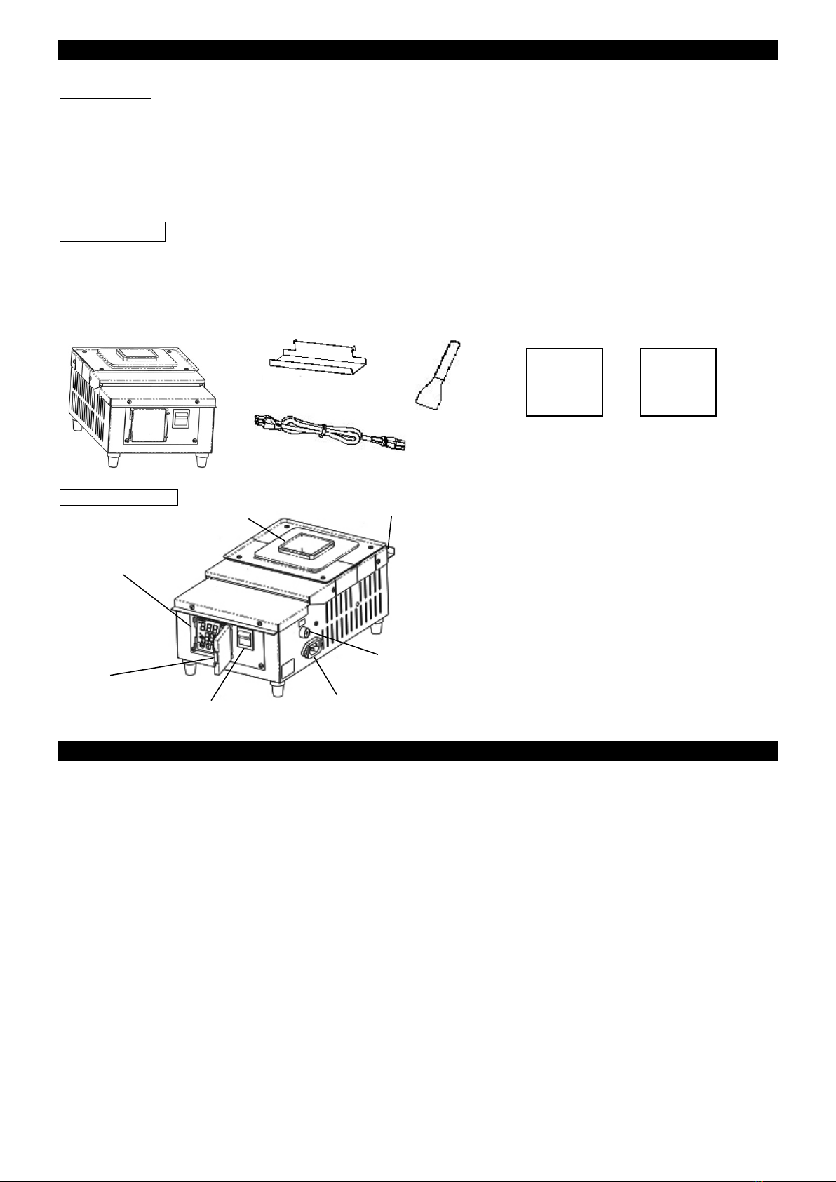
2.2 Unpacking.............................................................................................................................................................................1
3. Rules for Safe Operation ............................................................................................................................................................1
4. Operation Instructions.................................................................................................................................................................2
4.1 Set up...................................................................................................................................................................................2
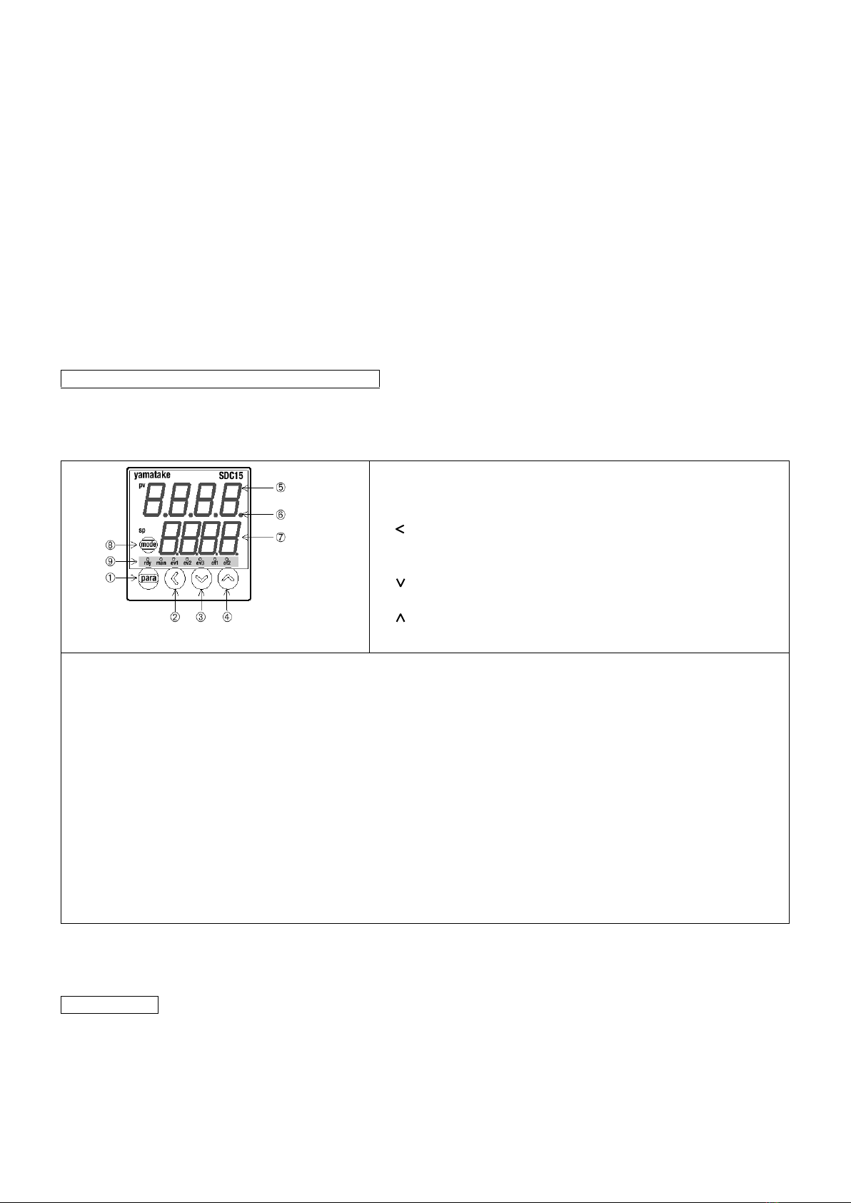
4.2 Name of Parts and Control Panel Functions.........................................................................................................................3
4.3 How to set.............................................................................................................................................................................3
5. Maintenance...............................................................................................................................................................................4
6. Troubleshooting..........................................................................................................................................................................1
7. Replacement Parts.....................................................................................................................................................................1
7.1 Replacement Parts...............................................................................................................................................................1
7.2 Replacement Procedures.....................................................................................................................................................1
Specifications
Model
POT-50C
Voltage
110-120V , 220 - 240V AC 50/60 Hz
Power Consumption
470-610W , 370 - 430W
Maximum Current
25A , 11A (at solder temperature 25oC / 77oF)
Solder Bath
Temperature
Room temp.--- 500oC / 932oF
Unit Dimensions
174(W) x 285(D) x 142(H) (6.9 X 11.2 x 5.6 inch)
Solder Bath
Dimensions
50(W) x 50(D) x 50(H)
(2 x 2 x 2 inch)
Weight
Approx.4Kg (75 lb)
Max. Solder Volume
Approx. 850g (1.9 lb)
Approx. 1900g (4.2 lb)
Solder Bath Material
Cast Iron
Power Cord Length
1.5m (4.9 ft.) (3 core cord) ground plug
WARNING
Before using the solder pot, read the Operation Manual. Failure to follow the safety precautions and
instructions in this manual could result in serious injury and property damage.
WARNING
Failure to obey a safety warning could result in serious injury or death to yourself or to others. Always
follow the safety precautions to reduce the risk of electric shock, fire or personal injury.
CAUTION
Failure to obey a safety caution may result in a minor or moderate injury to yourself or to others.
Always follow the safety precautions to reduce the risk of electric shock, fire or personal injury.
LEAD-FREE APPLICABLE SOLDER POT
POT-50C
OPERATION MANUAL

1
2. Introduction
2.1 Features
⚫Perfect for insulation-removal and preparative soldering of transformer leads and other leads
(POT-50C)
⚫Accurate PID temperature control. User defined bath temperature regulation by switching to sensor
feedback ON/OFF control.
⚫Dual digital display shows the set temperature and measured temperature at the same time.
⚫Fitted with extra long life ceramic heater.
2.2 Unpacking
Please make sure that all the items listed below are included, and the unit functions properly. Please store
the packaging for future shipment or repair.
Packaged items:
2.3 Name of Parts
3. Rules for Safe Operation
1. DO NOT USE IN DANGEROUS ENVIRONMENTS.
Do not use the solder pot in damp or wet locations or expose it to external environmental conditions,
particularly rain. Never use it in an explosive atmosphere. The heat from the heater can ignite fumes.
Be sure that the work area is well ventilated.
2. KEEP CHILDREN AND BYSTANDERS AWAY FROM THE SOLDER POT.
Do not let bystanders touch the solder pot. All bystanders should be kept a safe distance from the
work area.
3. USE FOR THE RIGHT JOB.
Do not use the solder pot for any purpose other than solder dipping work. For example: The solder
pot should never be used to warm water or other liquids.
4. WEAR PROPER APPAREL AND SAFETY GLASSES, MASK AND GLOVES.
Do not wear loose clothing (such as a necktie). Tie up long hair. Clothing or hair can burn on
contact with the molten solder or surrounding heated parts.
5. CONNECT TO THE SPECIFIED AC POWER SUPPLY.
The power voltage for this solder pot is indicated on the unit. Never plug the solder pot into any other
voltage.
Operation
Manual
Spatula
Dross tray
Operation manual
Main unit
Power cord
SDC15
Operation
Manual
Controller manual
Fuse holder (Fuse)
Power switch
Solder bath
Digital control panel
Dross tray
Power cord inlet
Protective cover

2
6. DO NOT ABUSE THE POWER CORD AND INSPECT IT PERIODICALLY.
Never yank the power cord to disconnect it from the receptacle. Keep the power cord away from
heat, oil and sharp edges. If it is damaged, replace it.
7. FOR FACTORY USE ONLY
This unit has noise proof circuit for factory use. If used in a home environment it may affect
surrounding electrical appliances.
4. Operation Instructions
4.1 Set up
1. Hook the dross tray to the top-plate. It is possible to set
the dross tray on 3 sides of the unit so you can position it to
suit your needs.
2. Make sure the Power Switch is in the OFF position before inserting the power cord into the power cord
inlet and plugging the other end into a power outlet.
WARNING
To prevent fire, burns, and possible serious injury or damage:
⚫Keep the solder pot away from flammable substances and materials in the work area.
⚫Be sure to position the solder pot on a firm metal bench. The solder pot is heavy when filled
with solder and the solder bath and surrounding area becomes very hot.
⚫Unplug the solder pot power cord immediately if there is burnt smell or unusual heating occurs.
Do not use the solder pot again, and return it to the distributor you purchased it from.
⚫Do not leave the solder pot unattended when it is hot as the pot and surrounding area becomes
very hot.
⚫Do not touch any part of the unit other than the power switch or the control panel when it is
switched ON.
Top plate
WARNING
Please observe the following in order to prevent solder splashing.
The splashed solder may badly burn you. Please be careful.
・Do not let the spatula get wet.
Steam is generated when a wet spatula contacts the molten solder. This may
cause solder to splash.
・Please use only the bundled spatula when you would like to
remove oxide.
Anything used in place of the spatula (Spoon,etc.) may cause solder to splash.
The spatula has unique features which cannot be substituted.
・Spatula surface must be clear and smooth.
Anything adhering to the spatula may cause solder to splash.
・If spatula has rust, please replace it with a new one.

3
3. Place the required amount of solder into the solder bath and turn the unit ON. Ideal solder level is
5mm below the rim of the bath.
4. Following the Control Panel setting procedure, input the temperature settings. This unit is set to
270 °C (518°F) prior to shipment.
5. When the settings are completed the Output Lamp (ot1) will light and temperature control begins. The
solder will melt in 7~8 minutes so put the solder into the pot little by little until it reaches the right level.
When the measured temperature (PV) and the set temperature (SP) are the same, the Output Lamp
(ot1) will flash and the temperature will be stable. The solder will be melted and work can begin
approximately 20 minutes after starting the temperature control. Before dipping, remove the oxidized
solder dross with the spatula and make sure the solder surface is clean.
6. Turn the unit OFF when not in use or when you are away from it.
4.2 Name of Parts and Control Panel Functions
The solder pot controller is a general-purpose model. The operator only sets temperature.
If you want to change the set up and parameter settings please refer the SDC15 operation manual included
with this solder pot. You can change the temperature display from Celsius to Fahrenheit.
①Para key (No need to use)
Changes the displayed item.
→Refer to the ‘SDC15 operation manual’.
②key
Changes the set value by moving the cursor to the digit
to be changed.
③key
Decreases the value when changing the set value.
④key
Increases the value when changing the set value.
⑤Upper display (PV value)
Displays the measured value (PV).
If the sensor is open, the alarm code [AL03] will be displayed. Return the solder pot to the distributor
for repair.
⑥Auto-tuning (AT) / Self-tuning (ST) display lamp
→Refer to the ‘SDC15 operation manual’.
⑦Lower display (SP value)
Displays the Set Value (SP). Shows the displayed value and measured value when changing the
settings.
⑧Mode key (No need to use)
By pressing this key for over 1 second it is possible to switch the modes. →Refer to the ‘SDC15
operation manual’.
⑨Mode display lamp
ot1 : Lights up while the heater is ON.
rdy, man, ev1, ev2, ev3, ot2 : No light up →Refer to the ‘SDC15 operation manual’.
Note : Do not use sharp objects, such as mechanical pencils, to press the keys on the control pad. This
may damage the pad.
4.3 How to set
Example procedure to enter 400 oC /752oF as the set value (SP) (PV value at 30 oC/ 86oF)

4
1. Enter the setting mode
Press the key to enter the SP
setting mode.
The lowest digit in the SV
display flashes.
4.Setting the 100 digit.
Move the flashing digit to
the 100 digit by pressing
key.
2. Setting the 10 digit
Press the key until the 10
digit flashes.
The selected digit flashes in the
order shown in the illustration
below.
5.Increase /decrease of the value
The key is used to increase
and the key is used to
decrease the value.
3. Increase /decrease of the
value
The key is used to increase
and
the key is used to decrease
the value.
6.Registering the set value
After finishing the settings
please wait for 2 seconds
without pressing any buttons.
When the display stops flashing
the set value is confirmed and
the operation display is shown.
Note 1: When nothing is input for over 2 seconds during the setting, the flashing value will be confirmed automatically and
operation display will be shown.
Note 2: It is not possible to set the values to more than the maximum temperature of 530 °C /986 °F.
Note 3: After setting is completed, close the protective cover. This will help minimize damage and keep the control panel clean.
Note 4: The unit operates at the old temperature while setting the new temperature.
5. Maintenance
⚫Keep the level of molten solder approximately 5mm below the rim of the solder bath.
⚫When using the solder pot for long periods, oxidized dross may collect around the walls of the solder
bath. This can cause poor heat transmission from the heater, overheating and insufficient heating of the
solder. Scrape the walls of the solder bath periodically with the spatula included with the unit to remove
oxidized dross.
WARNING
To prevent fire, burns, and possible serious injury, wear glasses, gloves and a mask before doing
maintenance.

1
6. Troubleshooting
Trouble: The solder does not melt.
a) The temperature setting display does not flash
Cause
Countermeasure
The Power Cord is unplugged at either end.
Plug it in.
The Power Switch is in the OFF position.
Set the power switch to the ON position
The Power Cord is damaged.
Replace the power cord.
The Fuse is blown.
Replace the fuse.
b) The temperature setting display flashes
Cause
Countermeasure
The set temperature is lower than the
temperature at which the solder melts.
Set the temperature to higher than that the solder
melting temperature.
The heater is damaged.
Replace the heater.
The alarm code display is shown.
Check the alarm code table in the SDC15
operation manual.
Return your goot distributor for service if you cannot solve the trouble above.
7. Replacement Parts
7.1 Replacement Parts
No.
Item
No.
Item
1
Heater (110 - 130V)
Heater (220 - 240V)
5
Heat Resistant Board Set B-50 for
POT-50C
2
Heater Block *Not required for POT-50C
3
Cast Iron Bath for POT-50C *Built-in heater
block
6
Dross Tray
7
Spatula
4
Fuse 15A 250V for 110-130V model
Fuse 10A 250V for 220-240V model
8
Power Cord
7.2 Replacement Procedures
POT-50C
Top Plate A
Top Plate B
⑧
①
④
⑤
⑥
⑦
③
WARNING
Turn the unit OFF and unplug the power outlet before changing the solder bath, heater or heat
resistant board. Do not start removing the solder bath or the parts before the unit has completely
cooled down.

2
Replacing the bath and heater.(POT-50C)
1. Loosen the two screws in Top plate B and remove the Top plate B.
2. Loosen the two screws in Top plateA and remove the Top plateA.
3. Remove the nuts from the Terminal block. Take care not to loosen the Lower nuts underneath when
doing this.
4. Remove the heater from the heater-opening. Be sure that the sleeve does not stick on the heater.
Note: The sleeve may come out with the heater when removing. Reinsert the sleeve in
heater-opening.
5. Remove the M4 screw of the terminal block and remove the ground terminal for the solder pot.
6. Loosen the Bath Fixing Screw on the right side of the unit. Lift the bath directly upwards to remove
from the main body.
7. Put the new heater and/or bath in place and reverse the steps above to reassemble.
8. Tighten the Bath Fixing Screw so that the bath does not move.
Heater lead
Heater lead
Upper nut
Lower nut
Terminal block
te
Heater
Sleeve
M4 screw
Ground terminal
Washer
1
2
3
4
5
6
Bath Fixing Screw
Notched washer
Spring Washer

3
For service, accessories and etc, Contact your nearest distributor or following:
SOLDERING IRONS, EQUIPMENT & ACCESSORIES
TAIYO ELECTRIC IND.CO.,LTD www.goot.co.jp
TEL:81-84-951-1512 FAX:81-84-951-9531
A4190HL00 2019-2-15
Other Goot Soldering Gun manuals

Goot
Goot TP-100 Instructions for use

Goot
Goot PX-501 User manual

Goot
Goot NC-100R User manual

Goot
Goot SVS-500 User manual

Goot
Goot POT-100C User manual

Goot
Goot Anti-Static Series Instructions for use

Goot
Goot RX-892AS User manual

Goot
Goot ST-27 User manual

Goot
Goot XST-80 User manual

Goot
Goot RX-701AS Series User manual