manuals.online logo
Brands
  1. Home
  2. •
  3. Brands
  4. •
  5. aoyue
  6. •
  7. Soldering Gun
  8. •
  9. aoyue 8011 User manual

aoyue 8011 User manual

8
88
8
PROBLEM 1: THE UNIT HAS NO POWER
1. Check if the unit is switched ON.
2. Check the fuse. Replace with the same type if fuse is blown.
3. Check the power cord.
4. Verify that the unit is properly connected to the power source.
PROBLEM 2: TEMPERATURE DISPLAY IS ALWAYS ABOVE 400
o
C
Descri tion: Constant display of abo e 400
o
C temperature from the panel
then displays “Err” on the panel after a few minutes.
SOLUTION:
The thermal sensor may be broken and needs to be replaced.
PROBLEM 3: TEMPERATURE DISPLAY IS ALWAYS BELOW 60
o
C
Descri tion: Constant display of below 60
o
C temperature from the panel
then displays “Err” on the panel after a few minutes.
SOLUTION:
Turn OFF unit and then ON again. If Display still shows “Err” then the
Heating element may be broken and needs to be replaced.
PROBLEM 4: DISPLAY PANEL SHOWS UNRECOGNIZABLE
CHARACTERS
SOLUTION : Switch unit OFF, wait a few seconds and ON again. If problem
persists contact endor
OTHER PROBLEMS NOT MENTIONED:
Contact the endor.
OPERATING GUIDELINES
Automated Hot Bar
Soldering System
INSTRUCTION MANUAL
Thank you for purchasing the AOYUE 8011
Automated Hot Bar Soldering System.
Please read this manual before operating the equipment.
Keep manual in accessible place for future reference.
8011
2
22
2
Main Station
Power in ut: 220V
Station Dimensions: 400(w)x580(h)x580(d)mm
Power consum tion: 500W peak
Tem erature range: 100°C - 350°C
The 8011 Automated Hot Bar Soldering System is equipped
with a three way micro adjust system two Powerful magnified
camera and LCD screen for precise mo ement adjustment.
Its CPU controlled timer and temperature controls pro ide
precise timing and temperature stability. Finally its automated
pneumatic system pro ides accurate and easy repeatability .
SPECIFICATIONS
Specifications are subject to change without prior notice
PRODUCT DESCRIPTION
TABLE OF CONTENTS
Product Description ———————————–— 2
Specifications ————————————–——— 2
Safety Precautions ———————–—————— 3
Initial Setup ————————–———————— 3
Control Panel Guide ———–-————————— 4
Operating Guidelines ————————--—- 5 — 7
Basic Troubleshooting Guide ————–—–———
8
7
77
7
7. Upon finishing one complete automated cycle the pre iously entered
temperature and timer settings will be sa ed to the CPU memory.
Note: The Emergency stop button can be used to stop the hot bar tool from
automatically descending. (see “Emergency stop button” for details)
5. MANUAL CONTROL
1. Automatic or Manual Control can be selected by pressing the
SELECT button. (“10” from control panel guide).
2. When the RED Lamp is lighted it means the system is currently in
Manual control mode.
3. If the Green Lamp is lighted the system is in automatic control
mode, push the SELECT button to switch to manual control mode.
4. During the manual control mode the manual control buttons(“11
and 12” from control panel guide) will be acti ated.
5. Pressing the In/Out button (“12” from control panel guide) will
control the platform mo ement.
6. Pressing the UP/Down button (“11” from control panel guide) will
control the Hot Bar Tool mo ement.
7. The Platform can only be controlled when the Hot bar tool is at the
up position.
6. EMERGENCY STOP BUTTON
1. In case of immediate requirement to stop the automated soldering
cycle the Emergency Stop Button can be pushed. (“15” from
control panel guide)
2. When emergency stop button is engaged the hot bar soldering tool
would mo e to the “up” position while the platform would mo e into
the “in” position. The system would be locked to manual control
mode.
3. The Platform and hot bar tool can then be manually adjusted to the
adequate position.
4. To disengage Emergency stop mode , unlock the Emergency stop
button by turning it clockwise.
OPERATING GUIDELINES
6
66
6
IMPORTANT: Ne er allow temperature setting abo e 300 degrees Celsius
for pro-longed period. Temperature setting at lower temperature will
preser e heater life.
5. The Timer can be adjusted by pushing the “+” and “-” buttons of
the Timer control buttons. (“9” from control panel guide).
6. The Timer display (“8” from control panel guide) will show the
current set timer settings.
7. Timer settings can only be adjusted during automated control
mode.
Note: The Set Temperature and Timer settings will automatically be sa ed
into the CPU memory once one complete cycle of the automated
procedure is finished.
4. AUTOMATIC CONTROL
1. Automatic or Manual Control can be selected by pressing the
SELECT button. (“10” from control panel guide).
2. When the Green Lamp is lighted it means the system is currently
in Automatic control mode.
3. If the Red Lamp is lighted the system is in manual control mode,
push the SELECT button to switch to automatic control mode.
4.
To initiate the automatic soldering procedure push both start
buttons simultaneously (“13,16” from control panel guide).
5. The automatic soldering cycle:
●
The platform mo es in
●
If platform is completely in, the hot bar soldering tool would
descend.
●
When the hot bar soldering tool has reached the platform count
down timer would commence.
●
With Count down completed, hot bar tool would mo e back up.
●
The platform slides out to original position.
6. The automatic soldering cycle can be repeated by pressing both
start buttons again.
OPERATING GUIDELINES
3
33
3
CAUTION: Im ro er usage can cause serious injury to ersonnel and/or damage
to equi ment. For ersonnel safety, lease follow these recautions:
●
Check each component after opening the package to make sure e erything
is in good condition. Do not use item if isible damage is seen, report the
issue to your endor.
●
Power off unit and unplug the de ice when mo ing the de ice from one loca-
tion to another.
●
Do not subject the main unit to physical shock
- Ne er drop or sharply jolt the unit.
- Contains delicate parts that may break if the unit is dropped.
●
Always connect power to a grounded receptacle.
●
Tip temperature may reach as high as 350°C when switched ON.
●
Disconnect from power source if the unit will not be used for a long periods.
●
Use only genuine replacement parts.
●
Soldering process produces smoke — use on well entilated place.
●
Do not try to alter or repair unit, bring to qualified ser ice center for repairs.
●
Ne er insert body parts between the paths of the mo ing platforms.
1. Place unit on top of a flat and stable work table.
2. LCD Monitor — Pull out the LCD Monitor mounting bracket on each
side of the unit. Mount both LCD monitors. Attach the 5 pin LCD moni-
tor connectors to the base of the upper control box and its other ends
to the LCD monitor.
3. Air com ressor** — Attach Air compressor tube to the unit. Turn
off the main al e at the air compressor. Switch on the air compressor
when gauge at the air compressor reaches 0.2 MPA turn on the main
al e.
4. Make sure power switch is turned OFF before plugging the de ice to
the main power source.
Note: In order for pneumatic system to function, Compressed air should
be fed into system. ** Air com ressor is sold se arately.
SAFETY PRECAUTIONS
Initial Setu
4
44
4
LEGEND:
1 — Pressure Adjustment Knob
2 — Pressure Gauge
3 — 8 in camera in ut socket
4 — Brightness adjustment of Lower Lam
5 — Brightness adjustment of U er Lam
6 — Tem erature dis lay.
“C” denotes actual Tem erature, “c” Denotes Set Tem erature
7 — Tem erature Adjustment Buttons. “+” increase. “-” decrease.
8 — Timer Dis lay
9 — Timer Adjustment Buttons.“+” increase. “-” decrease.
10 — Mode Selection Button.
Green lam –Automatic control. Red lam – Manual control
11 — Hot Bar module Descend and Ascend Button.
For use only in Manual Control.
12 — Adjustment Platform In/Out Button. For use only in Manual Control.
13 , 16 — Start Automation Button.
14 — Reserved Button.
15 — Emergency Sto Button for use during Automatic control.
AIR PRESSURE
CONTROL
TEMPERATURE
+ -
AUTO-
MATIC
CONTROL
MANUAL
CON-
TROL
SELECT
UP /
DOWN
IN/ OUT
MANUAL CONTROL
AOYUE
8011
AUTOMATED HOT BAR
SOLDERING SYSTEM
®
BRIGHTNESS
ADJUSTMENT
UPPER LOWER
Camera
In ut
0010
-
--
-
+
++
+
1
2
3 4 5
6
7
8
9
10
11
12
START
EMERGENCY START
VAC
13 14 15 16
CONTROL PANEL GUIDE
TIMER
+ -
5
55
5
Please refer to the CONTROL PANEL GUIDE page for buttons and display
panel directory.
1. INITIAL PROCEDURES
1. Make sure power switch (Located at the back of the unit) is turned
OFF before plugging the de ice to the main power source.
2. Switch ON the main power switch (Located at the back of the unit).
3. Display panels, 6 and 8 will display “C100” and “0010” default
parameters.
2. ADJUSTING PRESSURE
1. Adjust to desire pressure le el using the Air pressure control Knob,
“1” from control panel guide. Pull on the knob to unlock it before
adjusting pressure le el. Push knob back in to lock into place.
2. If Higher pressure is needed the pressure control knob located at
the left side of the unit can be adjusted for higher pressure le el,
then use the Air pressure control Knob (“1” from control panel
guide) to fine adjust the pressure to desired le el.
3. ADJUSTING TEMPERATURE AND TIMER
1. During automated control mode. Green lamp lighted.
2. Adjust to desire temperature settings using the temperature control
buttons. (“7” from control panel guide).
3. The Temperature display window (“6” from control panel guide).
Will initially display a number with the Capital letter “C” at the
beginning. This indicates the number displayed is the actual
temperature. Upon pressing the temperature control buttons. The
display will change to small letter “c” indicating the temperature is
being set and the number shown is the current set temperature for
the Hot bar soldering tool.
4. The heating element can be temporarily turned OFF and ON by
simultaneously pressing the “+” and “-” buttons of the temperature
adjustment buttons. The Display would show “OFF” to indicate the
heater is currently turned off.
OPERATING GUIDELINES

Other aoyue Soldering Gun manuals

aoyue Tesla Series User manual

aoyue

aoyue Tesla Series User manual

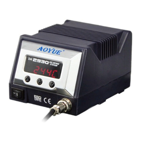
aoyue Int2930 User manual

aoyue

aoyue Int2930 User manual

aoyue 968A+ User manual

aoyue

aoyue 968A+ User manual

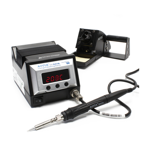
aoyue INT9378 User manual

aoyue

aoyue INT9378 User manual

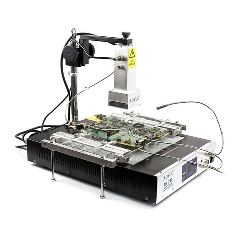
aoyue Int732 User manual

aoyue

aoyue Int732 User manual

aoyue 2900 User manual

aoyue

aoyue 2900 User manual

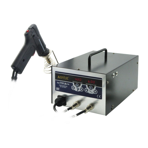
aoyue Int701A++ User manual

aoyue

aoyue Int701A++ User manual

aoyue Tesla User manual

aoyue

aoyue Tesla User manual

aoyue 469 User manual

aoyue

aoyue 469 User manual

aoyue INT 2703A+ User manual

aoyue

aoyue INT 2703A+ User manual

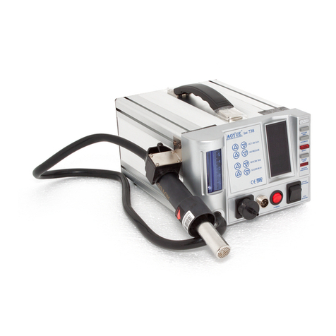
aoyue INT 738H User manual

aoyue

aoyue INT 738H User manual

aoyue SP4000 User manual

aoyue

aoyue SP4000 User manual

aoyue 937 Plus User manual

aoyue

aoyue 937 Plus User manual

aoyue 2901 User manual

aoyue

aoyue 2901 User manual

aoyue SP2000+ User manual

aoyue

aoyue SP2000+ User manual

aoyue 853a+ User manual

aoyue

aoyue 853a+ User manual

aoyue 888A User manual

aoyue

aoyue 888A User manual

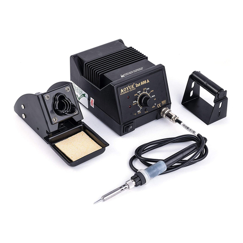
aoyue Int936A User manual

aoyue

aoyue Int936A User manual

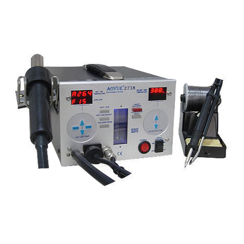
aoyue 2738 User manual

aoyue

aoyue 2738 User manual

aoyue SP2000 User manual

aoyue

aoyue SP2000 User manual

aoyue INT 2702A+ User manual

aoyue

aoyue INT 2702A+ User manual

aoyue Int3210 User manual

aoyue

aoyue Int3210 User manual

aoyue INT 738 User manual

aoyue

aoyue INT 738 User manual

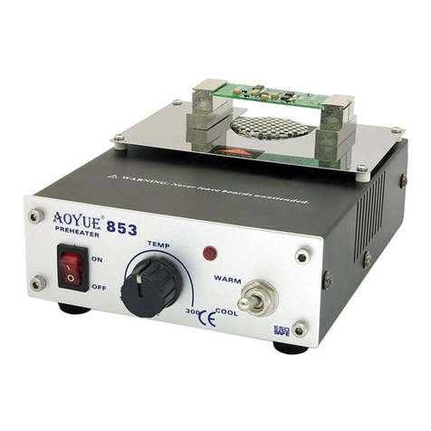
aoyue 853 User manual

aoyue

aoyue 853 User manual

Popular Soldering Gun manuals by other brands

FTM Technologies SI1R user manual

FTM Technologies

FTM Technologies SI1R user manual

Pace ST35 w/PS-90 Iron Operation and maintenance manual

Pace

Pace ST35 w/PS-90 Iron Operation and maintenance manual

Bakon 3200 instruction manual

Bakon

Bakon 3200 instruction manual

Proxxon Gaslotset MGS manual

Proxxon

Proxxon Gaslotset MGS manual

jbc SFR-A instruction manual

jbc

jbc SFR-A instruction manual

jbc CL8010 instruction manual

jbc

jbc CL8010 instruction manual

Hakko Electronics FX-100 instruction manual

Hakko Electronics

Hakko Electronics FX-100 instruction manual

HAKO FX-8804 instruction manual

HAKO

HAKO FX-8804 instruction manual

SATA 02002A user manual

SATA

SATA 02002A user manual

Velleman HRJA151 user manual

Velleman

Velleman HRJA151 user manual

Weller WSM 1 operating instructions

Weller

Weller WSM 1 operating instructions

Vishay Precision Group Micro-Measurements Mark V Operating and maintaining

Vishay Precision Group

Vishay Precision Group Micro-Measurements Mark V Operating and maintaining

ersa i-CON 1V quick guide

ersa

ersa i-CON 1V quick guide

Atten ATETOOL AT-689A user manual

Atten

Atten ATETOOL AT-689A user manual

Surtek 112554 User manual and warranty

Surtek

Surtek 112554 User manual and warranty

Parkside PLBS 30 A1 Operation and safety notes

Parkside

Parkside PLBS 30 A1 Operation and safety notes

AlienTek T100 user manual

AlienTek

AlienTek T100 user manual

Weller FT12 operating instructions

Weller

Weller FT12 operating instructions

manuals.online logo
manuals.online logoBrands
  • About & Mission
  • Contact us
  • Privacy Policy
  • Terms and Conditions

Copyright 2025 Manuals.Online. All Rights Reserved.