Goot RX-701AS Series User manual

R X-711A S
TEMPERATURE-CONTROLLED
SOLDERING STATION
This is a common operation manual for RX-701AS &
RX-711AS. Each model number is mentioned in the text.
Be sure to read properly for your model.
1. SAFETY MARK DEFINITIONS ...........................2
2. FOR SAFE OPERATION .....................................2
3. PACKAGE CONTENTS / NAME OF PARTS ......4
4. OPERATION ........................................................5
5. MAINTENANCE ..................................................7
6. IN THE EVENT OF FAILURE ..............................9
7. SPECIFICATIONS................................................9
8. REPLACEMENT TIP ......................................... 10
9. PARTS LIST ...................................................... 11
10. SOLDERING IRON STAND ST-27 INSTRUCTIONS.......... 12
TAIYO ELECTRIC IND.CO.,LTD.
KEEP THIS MANUAL FOR FUTURE REFERENCE
Thank you for buying the goot Soldering Station.
Read this Operation Manual before using your sol-
dering station.
NOTE
www.goot.co.jp E-mail: info@goot.co.jp
2-16-8 Yamate, Fukuyama, Hiroshima 720-0092 JAPAN
OPERATION MANUAL
RX-701AS/711AS
model RX-701AS/22, RX-701AS/23, RX-701AS/24
RX-711AS/22 , RX-711AS/23, RX-711AS/24

2
WARNING
CAUTION
NOTE
Failure to obey a safety warning could
result in serious injury or death to
yourself or to others, or in physical
damage
Failure to obey a safety warning could
result in injury to yourself or to others,
or in physical damage.
A note or word of advice.
In this manual, the following safety marks are used.
1. SAFETY MARK DEFINITIONS
2. FOR SAFE OPERATION
1. Do not use in dangerous environments. Never
use it in damp, humid or wet locations (includ-
ing outside), or near flammable substances.
2. Keep children and bystanders away from the
unit.
3. Turn off the power when not in use.
4. This soldering station is an electrical tool used
to solder parts and melt solder. Do not use the
soldering station for any purpose not intended.
For example : the soldering station should never
be used to warm water or other liquids.
5. Wear proper apparel and safety glasses.
6. Connect to a correct AC power supply. Do not
use with any power voltage other than the indi-
cated voltage.
7. If the power cord is damaged, stop using imme-
diately and turn off the power. Return to the
distributor for replacement.
8. Be sure to use the ST-27 soldering iron stand
included with this soldering station. Other solder-
ing iron stands may melt the parts of this unit.

3
WARNING
This soldering handle must be placed
on its stand when not in use
9. Plug the machine into a grounded 3-prong plug.
Make sure that the machine must be grounded
at all times to prevent electrical shocks and
static electricity.
10. The soldering iron is not intended for use by
persons (including children) with reduced physi-
cal, sensory or mental capabilities, or lack of
experience and knowledge,unless they have
been given supervision or instruction concern-
ing use of the appliance by a person responsible
for their safety. Children should be supervised to
ensure that they do not play with the appliance.
11. Do not disassemblexx the control unit.
12. This appliance can be used by children aged from
8 years and above and persons with reduced
physical, sensory or mental capabilities or lack
of experience and knowledge if they have been
given supervision or instruction concerning use
of the appliance in a safe way and understand
the hazards involved.
13. Cleaning and user maintenance shall not be
made by children without supervision.

4
■付属はんだこて台
ST-27
■制御部
■こて部
保護カバー
止めねじ
ヒーター 通電ランプ
コネクター
温度表示切換
スイッチ
(
RX-711A S
のみ)
温度表示
(
RX-711A S
のみ)
保護カバー
温 度 校 正 ボ リューム
(CAL.)
温度設定ツマミ
ネームラベル
電 源 スイッチ
こて先
ヒーターパイプ
グリップカバー
コネクター
スポンジ
ナット
アダプター
クリーナー
3. PACKAGE CONTENTS / NAMES OF PARTS
Temperature
Display
(RX-711AS only)
Temperature Display
Changeover Switch
(RX-711AS only)
Protective Cover
Fixing Screw
Calibration
Screw
(CAL.)
Heat Monitor Lamp
Temperature
Setting Knob
Protective Cover
Connector
Connector
Brass Wool
Heat-Resistant
Sponge
Name Label
Power Switch
Rubber Grip Cover
Black Collar
Collar
Heater Barrel
Tip
■
Control Box
■
Soldering Iron
■
Soldering Iron Stand

5
4. OPERATION
1. Always place the machine and the soldering iron
stand on a stable worktable in a well-ventilated
area.
2. Connect the soldering iron to the control box.
Confirm the orientation of the plug.
3. Put the soldering iron into the soldering stand firmly.
4. Check that the power switch on the control box is
OFF (O side), and then plug in the control box.
5. Loosen the fixing-screw at the bottom left of the pro-
tective cover by Phillips-head screwdriver. Open the
protective cover for temperature setting.
A. RX·701AS only
1. Set the desired temperature using the
Temperature Setting Knob.
2. Switch the power switch ON (to I side). The Heat
Monitor Lamp will light up and the heater will
start heating up. When the Heat Monitor Lamp
flashes, the soldering station is ready to use.
B. RX-711AS only
1. Switch the Temperature Display Changeover Switch (at the
left of the front panel) to SET. Display shows setting tem-
perature.
2. Switch the power switch ON (to I side). The Heat Monitor
Lamp will light up and the heater will start heating up. The
temperature display initially shows “999” for approx. 10
seconds, then shows setting temperature.
3. Set the desired temperature using the
Temperature Setting Knob.
It may take time to completely stabilize the temperature.
When accurate temperature control is required, we
recommend waiting 2 minutes after device is switched on.
NOTE
WARNING
To prevent fire, do not use the sol-
dering station near flammable sub-
stances.Failure to obey this warning
could result in serious injury or death
to yourself or to others.

6
5. After setting the temperature, close the protective
cover and tighten the fixing-screw at bottom left with
a Phillips-head screwdriver.
6. Remove the solder scrap on the iron tip regularly with
the wet sponge of the soldering iron stand.
Approx. 2°C difference between the SET and MEAS display
may occur. In this case, there is no need to adjust the tip
temperature (by knob) on MEAS display. The factory default tip
temperature is set on SET display.
When the temperature display is set to MEAS, there is
a temperature fluctuation from 2°C to 3°C.
It may take time to completely stabilize the temperature. When
accurate temperature control is required, we recommend
waiting 2 minutes after device is switched on.
MEAS display has a 10-second delay. If the temperature
changes for less than 10 seconds, the display will not change.
Ex.) If the tip is rested on a wet sponge, temperature display
will continue to show set temperature (eg. 480°C) for approx.
10 seconds. Then it will start dropping. During those 10
seconds, the temperature-control circuit is working to recover
the set temperature.
NOTE
NOTE
NOTE
NOTE
CAUTION
WARNING
Never set the temperature over 500°C.
Your soldering station could be damaged.
Turn off and unplug the soldering station
if there is a burning smell, overheating, or
if the plastic parts deform. Do not use it
again and contact your nearest distribu-
tor. Continued use could result in serious
personal injury or damage.
4. Switch the Temperature Display Changeover Switch (at the
left of the front panel) to MEAS. Display shows the actual
tip temperature. When the Heat Monitor Lamp flashes, the
soldering station is ready to use. However if the unit is
switched ON again with 1 hour of being switched OFF, and
the displayed number is close to “000”, then it is showing
the actual tip temperature.

7
5. MAINTENANCE
5-2 REPLACEMENT OF HEATER
1. Remove the Collar by turning it in a
counter-clockwise direction.
2. Pull out the Heater Barrel, then pull
out the tip & Spacer from the heater.
3. Remove the Black Collar by turning
it in a counter-clockwise direction.
5-1 REPLACEMENT OF TIP
1. Remove the collar by turning it in a
counter-clockwise direction.
2. Pull out the heater barrel, then pull out
the tip from the heater.
3. Reassemble with new tip, reversing
these steps. ナット ヒーターパイプ
ヒーター
To prevent seizing, regularly pull out the tip from the
heater and remove the oxidized dross inside.
NOTE
Heater
Collar Heater Barrel
Collar
Heater Barrel
Spacer
Black Collar
WARNING
CAUTION
WARNING
CAUTION
Never touch the heater barrel, collar, or
adapter, to prevent personal injury or
burning yourself.
Do not hit or drop the tip or the heater, to
avoid deformation or breakage. The tip
life may be decreased when using lead-
free solder.
Turn off the main power switch (to O side),
and unplug the power cord before mainte-
nance. And be sure that the tip is cooled
down. Failure to obey this warning could
result in electric shock or serious injury.
Use only genuine goot replacement parts
for maintenance. The use of any other
parts may be hazardous and cause dam-
age to the unit.

8
5-3 TEMPERATURE CALIBRATION
(Tip thermometer required)
A. RX-701AS only
1. Set the desired temperature using the
Temperature Setting Knob.
2. While measuring the tip temperature with a tip
thermometer, adjust the CAL (Calibration Screw)
with Flat-head screwdriver to bring the mea-
sured temperature to the desired temperature
scale. The tip temperature increases when the
CAL is turned clockwise, and it decreases when
the CAL is turned counter-clockwise.
B. RX-711AS only
1. Switch the Temperature Display Changeover
Switch (at the left of the front panel) to SET.
2. Set the desired temperature using the
Temperature Setting Knob.
3. While measuring the tip temperature with a tip
thermometer, adjust the CAL (Calibration Screw)
with Flat-head screwdriver to bring the mea-
sured temperature to the desired temperature
scale. The tip temperature increases when the CAL
is turned clockwise, and it decreases when the
CAL is turned counter-clockwise.
5. Desolder the 3 locations of pins for the
heater. Remove the heater from the
PCB.
6. Solder the new heater to the PCB. Cut out the extra heater lead wire 3mm
or less from the PCB.
7. Next, about the PCB slot orienta-
tion. The PCB slots are offset from
center. The longer arc should be up.
The shorter arc should be down. The
Earth Pin should be down.
8. Reassemble, reversing these steps.
PCB Slot Orientation
Grip Exterior
Earth Pin
PCB
Longer Arc
Shorter Arc
PCB Slot
Ensure the PCB is inserted correctly
according to the above diagram.
Red Lead →H
White Lead→
S
Yellow Lead →C
S
C
H
3mmor
less
Cut
Red Lead →H
White Lead→S
Yellow Lead →C
S
C
H
3mmor
less
Cut
4. Disconnect the Earth Connector
from the Earth Pin; remove
the sleeve; remove the entire
assembly, pulling on the Earth
Collar.
アースーカラー
アースピン
アースコネクタ
Earth Collar
Earth Pin
Earth Connector

9
5-4 PLASTIC COMPONENT CARE
Do not allow gasoline, petroleum-based, permeable oil to contact any
plastic parts. It may damage the machine or the components. Use a
clean cloth to wipe the machine.
The factory default tip temperature is 350°C. The thermal
difference between the actual measured tip temperature and
the displayed temperature is in the range of +/-10°C at 200°C,
and 450°C(RX-701AS only) or 480°C(RX-711AS only). Tip
thermometer readings may vary slightly.
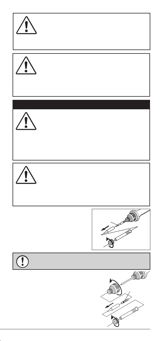
To prevent any damage to soldering station or other objects,
make sure to calibrate the tip temperature after replacement of
the tip or heater. If you do not have a tip thermometer, or you are
unable to calibrate, please contact your nearest distributor.
NOTE
NOTE
Proceed with the following steps if you have any problems.
1. Check that the power cord is not damaged. If you notice any signs of
damage, please contact your distributor.
2. If the cord is fine, use the below troubleshooting guide.
3. Turn off and unplug the soldering station if there is a burning smell, over-
heating, or if the plastic parts deform. Please contact your distributor.
4. If the machine is dropped, be sure to check the above troubleshooting
guide. If you notice any signs of damage, do not use it, and please contact
your distributor.
6. IN THE EVENT OF FAILURE
PROBLEM REASON ACTION
Power does not
turn ON.
Power cord unplugged? Connect it properly.
Power switch is OFF (O side). Turn switch ON (to I).
Power cord damaged? Contact distributor.
Fuse blown out? Contact distributor.
Heater does not
heat up.
Connector loose or
disconnected?
Connect it properly.
Heater damaged? Replace the heater (See 6-2).
Soldering-iron cord damaged? Replace the soldering iron.
Other problems PCB may be broken, contact to distributor.
7. SPECIFICATIONS
MODEL RX-701AS R X -711A S
Voltage 110V, 120V, 130V, 220V, 230V, 240V AC 50/60Hz
Power Consumption 65W
Output Voltage 24V
Temperature Setting Range 200-450°C (392-842°F) 200-480°C (392-896°F)
Insulation Resistance Over 100MΩ
Dimensions Control Box 146(L) ✕ 115 ( W ) ✕ 98(H)mm
Soldering Iron 197mm (w/o cord)
Weight Control Box 1.5kg (w/o cord)
Soldering Iron 44g (w/o cord)
Connecting Cord Length 1.2m
Power Cord Length 3-prong cord 1.5m
Leak Voltage Less than 2mV
Ground/Earth Resistance Less than 2Ω
Accessories
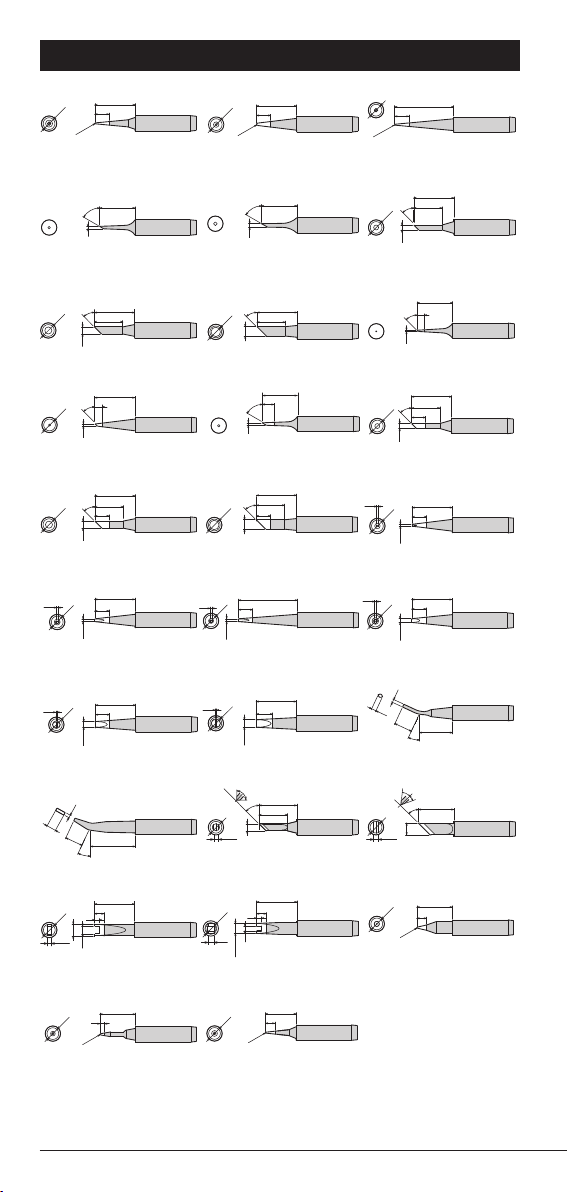
Soldering Iron Stand: ST-27, Tip: PX-60RT-B

10
PX-60RT-3C
PX-60RT-1C
60°
15
1
PX-60RT-1.5C
60°
15
1.5
12
17
φ
3
PX-60RT-LB
6
25
φ
5
PX-60RT-B
6
17
R0.5
φ5
PX-60RT-SB
6
17
R0.2
φ5
φ5
PX-60RT-0.8D
6
17
φ0.8
0.6
φ5
PX-60RT-1.2D
17
6
φ1.2
0.7
φ5
PX-60RT-2C
12
φ
2.1
φ5
17
45°
PX-60RT-0.5CR
3
0.5
15
45°
PX-60RT-0.8CR
3
0.8
φ5
17
45°
PX-60RT-2CR
17
6
12
φ2.1
φ5
45°
PX-60RT-4C
12
17
φ4
φ5
45°
PX-60RT-4CR
6
12
17
φ4
φ5
45°
PX-60RT-3CR
6
17
φ3
12
φ5
45°
45°
PX-60RT-1.2LD
6
25
φ1.2
0.7
φ5
PX-60RT-1.6D
6
17
0.5
φ1.6
φ5
6
17
0.5
φ2.4
φ5
PX-60RT-2.4D
1.8
14
7.5
25°
25°
1
PX-60RT-1.8H
2
R0.3
15
φ5
PX-60RT-SB2
7
17
0.5
φ3.2
φ5
PX-60RT-3.2D
4.0
1.2
19
7.5
PX-60RT-H
4
13
R0.2
φ5
PX-60RT-SI
4
15
R0.3
φ5
PX-60RT-S4
3.2
4
2
17
φ5
φ5
PX-60RT-R
1.5
17
24
2
φ4.2
φ5
PX-60RT-RT
2.5
45°
φ3
12
16
φ5
PX-60RT-3K
2
90˚
PX-60RT-5K
45°
15
φ5
24˚
40˚
φ5
2
PX-60RT-1CR
60°
15
5
1
R0.2
8. REPLACEMENT TIP

11
2
3
45
6
7
1
9. PARTS LIST
NO. Parts Name Code Note
①Soldering Iron Unit A0883AF00 RX-72GAS
②Heater B0882AH00 RX-72H
③Black Collar A0880HW00 RX-72GASAD
④Spacer A0880HS00 RX-72SS
⑤Tip B0672AB00 PX-60RT-B
⑥Heater Barrel A0880HP00 RX-72HP
⑦Collar B1362AJ00 TQ-77NUT
①

12
SOLDERING IRON STAND
S T-27
INSTRUCTIONS
WARNING
CAUTION
•High temperatures. Handle with care.
•To avoid injury, do not touch the metal
part of the stand. •To prevent fire, do
not use the ST-27 near flammable sub-
stances.
•Always place the stand on a stable
worktable, or other stable location, to
prevent injury or accident from dropping
it. •To avoid splattering solder scrap, do
not swipe the tip of the iron across the
brass wool. This is dangerous. •To pre-
vent fire or personal injury, be sure that
the stand has cooled sufficiently before
storing it.

13
Size 72(W) ×106(H) ×178(D)mm
Weight 485g
INSTRUCTION FOR USE
DIMENSIONS
NAMES OF PARTS / REPLACEMENT PARTS
Rub the soldering-iron tip on the moistened sponge.
Use the hole of the sponge for better cleaning.
Alternatively, push the soldering-iron tip in and out of the
brass wool a few times. Stab, not swipe.
The angle of the front opening
can be adjusted by loosening
screws on the side.
REPLACEMENT PARTS
Heat-Resistant Sponge / ST-53SP
Front Opening (with adjusting screws)
/ ST-27MS
Brass Wool (2balls) /ST-40BW
•
To avoid rust, do not pour water on the brass wool.
•
Sponge
tray and holding flange (of the front opening) are made of
phenol. Be aware that extended tip-contact may result in their
deterioration.
•
Remove the collected solder scrap regularly.
NOTE
Front Opening
ST-27MS
Adjusting Screws
Heat-Resistant
Sponge
ST-53SP
Brass Wool
ST-40BW

14

15

Printed in Japan, DECEMBER 2019 A0810AL04
This manual suits for next models
7
Table of contents
Other Goot Soldering Gun manuals

Goot
Goot NC-100R User manual

Goot
Goot ST-27 User manual

Goot
Goot TP-100 Instructions for use

Goot
Goot POT-100C User manual

Goot
Goot XST-80 User manual

Goot
Goot POT-50C User manual

Goot
Goot RX-822AS User manual

Goot
Goot Anti-Static Series Instructions for use

Goot
Goot RX-892AS User manual

Goot
Goot SVS-500 User manual