manuals.online logo
Brands
  1. Home
  2. •
  3. Brands
  4. •
  5. Hakko Electronics
  6. •
  7. Soldering Gun
  8. •
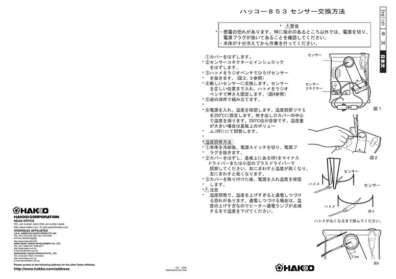
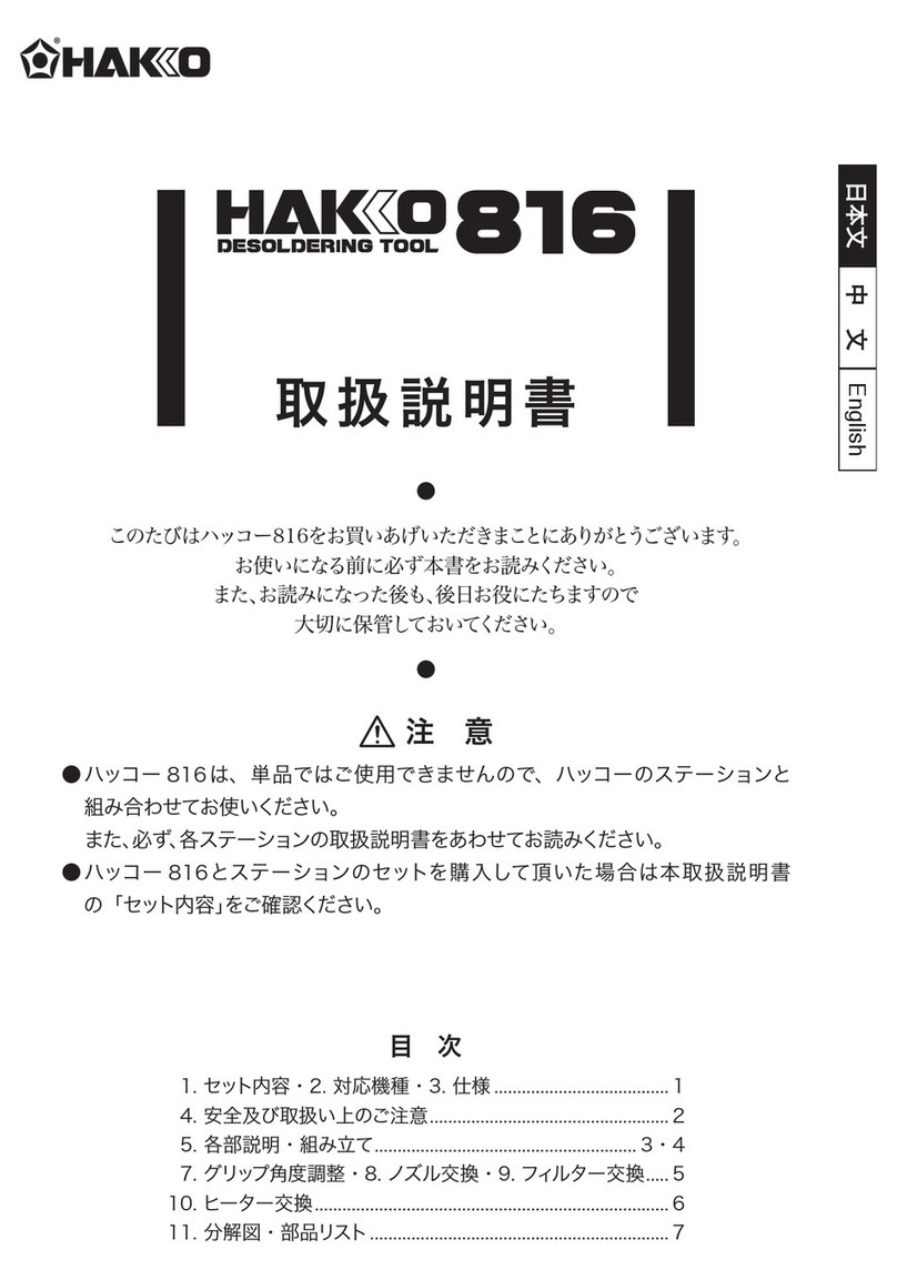
  9. Hakko Electronics A1560 User manual

Hakko Electronics A1560 User manual

https://www.hakko.com
© 2008-2020 HAKKO Corporation. All Rights Reserved.
OVERSEAS AFFILIATES
U.S.A.: AMERICAN HAKKO PRODUCTS, INC.
TEL: (661) 294-0090 FAX: (661) 294-0096
Toll Free (800) 88-HAKKO
4 2 5 5 6
https://www.HakkoUSA.com E-mail: [email protected]
SINGAPORE: HAKKO PRODUCTS PTE., LTD.
TEL: 6748-2277 FAX: 6744-0033
https://www.hakko.com.sg E-mail: [email protected]
HONG KONG: HAKKO DEVELOPMENT CO., LTD.
TEL: 2811-5588 FAX: 2590-0217
https://www.hakko.com.cn E-mail: [email protected]
Please access the web address below for other distributors.
https:// www.hakko.com
HEAD OFFICE
4-5, Shiokusa 2-chome, Naniwa-ku, Osaka 556-0024 JAPAN
TEL: +81-6-6561-3225 FAX: +81-6-6561-8466
https:// www.hakko.com E-mail: [email protected]
556-0024 󲚜󹟪󳃌󴭋󸴎󱴒󲕓󷒩2󱒫󵱹4󵦲5󱸹
󽙻 󽙬 󽙳 󽙡󽙏 06󽙐6561-1574󽙏󱗰󽙐󽙭 󽙨 󽙿 󽙡󽙏 06󽙐6568-0821
No.A1560

󾙓󷽱󳂦󲋲󱝫󸕟󱧾󱸇
󾙔󳂦󲋲󱸇
󾙕󱧾󱡱󳊶
󾙖 󳣢󱸇
手動片手はんだ送りこて
󾙓󸏈󳶾󱸇󳵚󳥰󹂬󱩏󹤶
󾙔󷽱󳂦󲋲󱝫󸕟󱧾󱸇
󾙕󳂦󲋲󱸇
󾙖󾙖󶒺󳡆󱸇󲙺󹜈
󾙗󳣢󱸇
󱖌󳫖󳎓󱒷󸉸󳤀󳣛󱟢󴲏󲰫
󾙖󾙓󾙖󾙔󹜕󾙗󾙓󾙗󾙔󹜕󲓺󱹍
    󳩹 󸈕 
󵧀󳄜󲓺󱹍󶦸
   󴟽 󳩹 󶤩        
󱧾󴲋󳇒󱸴󲋲󺁶󳂦󲋲󱚆

󴈦󴟽󽙪󽙨󽙳󵥌󷼇
󱧾󴲋󳇒󴲏󲰫󱧾󴲋󳇒󸉗
  󱛔   
󱞄󵜝󱜄󹮵󹢡󸎉󳡧󳶸󱛔󵥌󳼨󵔐󳙽
󱓙󳹁󸜥󲘿󳆹󱗰󵜝󳆹󲵱󹯟
󵥝󱒶  
󱗝󴔬󱷶󲙺󸆾󳵪󷋢󱕡󱺵󲙛󴁍󱕝󳢵
  
󲀩󱽢󹨱󹥦󴥔󲳻󶑡
󶦸󸴀󲒚󴄯󴩏󱩣󱡱󱟁
 󱗡 󶦸 󸅺 󵽍 󸍡 
󱗡󳡆󱧾󶎘󾙓󾙔󳡆
󷽱 
󱝫 󸕟 
󱧾


 
󸏈󳶾
󳵚󳥰󹂬󱩏
󷽱 
󱝫 󸕟 
󱧾







󳄜󴲋󳼨󴲏󲰫
󾙓󳤀󳣛󱟢󸠬󾙔󾙗󾙕󾙗
󾙔󳤀󳣛󱟢󹨣󾙖󾙕󾙗󾙚
󳤀󳣛󱟢󵧀󳄜󲓺󱹍󱖌󳫖
󴟽󳄜󲓺󱹍󳸧󶦸󶶳
󱸇󲙺󱮆󳏳󷽱󱸇
󴁤󱭄
󵸟󶢹󱶪󲋵
󱹒󷋨󴑶󳒋
󲒚󴄯󱧾󶎘󱧾󶎘󾙘󾙖󴔬
󸏈 󳶾   
󽙏󱛧󽙐
󴪑󳘌
󳤀󳣛󱟢
󳤀󳣛󱟢  󳤀󳣛󱟢
󶦸󽙏󸠬󽙐

󶦸
󵲂󸇩󴁋

󾙘󾙖󽚔 󽚔
󳤀󳣛󱟢
󾙖󾙗󹜕󽙏󽙐
󾙓󾙔󹜕󽙏󽙐
󾙕󱧾
󾙔󾙗󾙕󾙗󳄜󴲋󳼨
󾙖󾙕󾙗󾙚󳄜󴲋󳼨
󾙔󱗴󱒷
󾙓󴲋󳇒󸏈󶔱󾙕󾙗󾙒󸊤󲰫
󾙔󹥦󴴯󱨭󴲋󳇒󲰇󲰫󳎉󵥌
󱸇
󾙕󱧾󴲋󳇒󲰇󲰫󱧾󴲋󳇒󸉗󵥌󱧾󴲋󳇒
󴲏󱗡󲶐󸏈󳶾󵥌
󷼱󶀱󶉭󳂱󸰏󱧾󴲋󳇒󾙕󾙗󾙒󸏈
󳶾

はん だこて
手動片手
は ん だ 送りこて
󾙓 󶦸󶦸 
󳸭󱖌󳫖
󾙔   󶦸    󱗡  󲌟  󱚘 󱬧 󶦸  󱬪   
󹂩󱓙󹩌󸆅󱚄󵱹󲰇
󸠬
󴪑󳘌
󱖌󳫖󳎓󴟽󵽍󴲋󳇒󶓹󵜝󳏳󴲋󳇒󴈦󴟽󷼇
  
󹯟
󱓩󳷤󳺝󴂷󳷤
ヒーターの抵抗値を測定します
●各部名称
逆の順序で組み立てます
温度の校正をします
ヒーターを交換します
ヒーター交換方法
※各言語(日本語、英語、中国語、フランス語、ドイツ語、韓国語)の取扱説明書は以下の URL、
HAKKO Document Portal からダウンロードしてご覧いただけます。
(商品によっては設定の無い言語がありますが、ご了承ください。)
* 各國語言(日語、英語、中文、法語、德語、韓語)的使用説明書可以通過以下网站的 HAKKO
Document Portal 下載參閲。
(有一部分的產品沒有設定外語對應、請見諒)
* Instruction manual in the language of Japanese, English, Chinese, French, German, and Korean
can be downloaded from the HAKKO Document Portal.
(Please note that some languages may not be available depending on the product.)
https://doc.hakko.com
注意
■ 静電気対策品への取扱い注意
本製品は静電気対策が施されていますので下記の注意を厳守してください。
1. プラスチックは、絶縁物ではなく導電性プラスチックです。修理時には十
分注意を払い、活電部の露出・絶縁材の損傷がない様部品交換、修理を行っ
てください。
2. 必ず接地して使用してください。
󴪒󳘍
ESD 󲰉󾈵󵥄󱽢󷮫󵜝󹭰󹟶󳪄󳹊
󴂸󵥄󱽢󱲯󱺃󹨺󹥧󲴕󶑢󾙍 󳡇󱗴󾙍 󸏤󱛔󵥌󱗴󱒷󹭰󹟶󳪄󳹊󽙡
1. 󱓟󹨿󳡇󴁹󲔨󷃽󹥝󱘎󸻪󳼎󶢠󶧌󺁪󾙍󸳿󱕻󹥝󱘎󱸯󶾩󾈸󴁹󲴘󹥧󳒋󾙋 󱞄󵜝󳟾󴁍󳫘󹥝󱘎󳼩󾙍
󸏤󲴙󳏱󱒹󸅳󱛔󳄙󹥧󵯔󹥧󴥨󹥝󱘎󴀤󹧟󾙍 󱔪󱒹󸅳󳬨󲘢󶢠󶧌󴃮󳸄󾙋
2. 󵥄󱽢󲍨󱛔󵥌󱮇󸏤󱱪󳏳󳩻󲍲󾙋
CAUTION
■Handling precautions for ESD Safe products
This product contains electrostatic countermeasures, so please use the
following precautions:
1. Not all plastic parts are insulators, they may be conductive. Be careful not to
expose live electrical parts or damage insulating materials when performing
repairs or replacing parts.
2. Be sure to ground the product before use.
2020.9
MA01765XZ200916
A1560_JEC_WIN_200916.indd 1A1560_JEC_WIN_200916.indd 1 2020/09/16 10:34:042020/09/16 10:34:04
No.A1560
󱓩󳷤 English
󳺝󴂷󳷤
No.A1560
󱓩󳷤
English 󳺝󴂷󳷤
Be sure to remove the nut before removing the nipple. Removing the nipple
first could cause the heater leads to twist and cause a short circuit.
Resistance
value of
heating element
Resistance value
of sensor
NOTE :
󶡺󶎘󴄯
󴁍󳫖󵯊󵌣󱧶󱘎
󾙓󲴊󵯊󵌣󱧶󱘎󳊶󶦸󱼑󱣪󳘪󲈛󳊶󶦸󹠽󹎞󽙓󹠽󱒷󵯊󵌣󱧶󱘎󽙓󵈦󳎓󴁍󳫖󳸭󵯔
󸻈󱘎󱹓󶇲
󴁍󳫖󵯊󵌣󱧶󱘎󳹁󴩯
󴚘󴇈󵯊󵌣󱧶󱘎
1
󵯊󵌣󱧶󱘎󹥦󹠃󱠍 󱣪󳘪󲈛󹥦󹠃󱠍
󵯊󵌣󱧶󱘎󳊶󶦸󽙏󶟿󷋨󽙐
2
󾙘󾙖󴤈󶛇
󳢗󳌧󳟸󵲂󸇩󳍍
󳤝󵲂󳊶󶦸
󵯊󵌣󱧶󱘎
󳊶󶦸
󶟿
 󴁍󳫖󱷶󲋲󸀋󳎓󵯔󴚘󴇈
󴁍󳫖󳎓
󾙓󴲏󹂩󶐍󾙖󳫄󹃁󱼑󶐍󾙓󱷶󶐍󾙔󳫄󹃁󱔏󹜕
󶐍󾙗󳫄󹃁󱼑󶐍󾙓󱷶󶐍󾙔󳫄󹃁󱔏󹜕󹥦󹠃󱠍󲜽󴅞󱒹󳼎󵇼󹠟󲚜󽙓
󱭿󳼎󵯊󵌣󱧶󱘎󱼑󱣪󳘪󲈛󵯊󵥀󱕝󳩹󸈶

󾙔󴲏󹂩󹥦󹠃󱠍󱗴󵽍󲰫󳊶󶦸󴨐󴁸󷾨󳢗󴁋󽙓
󶷂󳩹󲍱󳌚󶘔󱔩󸴞󳩹󲞐󵧈
3



󶐍󾙖󷂕󷇢󶐍󾙗󷂕󱔏󹜕󽙏󵯊󵌣󱧶󱘎󽙐
󶐍󾙓󷂕󷇢󶐍󾙔󷂕󱔏󹜕󽙏󱣪󳘪󲈛󽙐
󶐍󾙕󷂕󷇢󵇏󹕙󹮞󱔏󹜕
󾙔󾙗󽙔󾙕󾙗󴟖󲟡󽙏󴟽󳄜󽙐
󾙖󾙕󽙔󾙗󾙚󴟖󲟡󽙏󴟽󳄜󽙐
󾙔󴟖󲟡󱗴󱒷
 󹂧󳸭󴈦󴴷󴵟󳇒
󵅂󵽍󱝫󵇏󳩹󴵟󳇒󵯔󱫂󵽍󳒋󽙓󴁍󳫖󵯊󵌣󱧶󱘎󳎓󽙓󸅱󹂧󳸭󴈦󴴷󴵟
󳇒󲴊󵇏󹕙󸴞󳩹󱭝󹥦󵇏󱸰
󹭣󳼨󹃁󳹁󱹙󳹤󸭛󴵟󳇒󴈦󴴷󸉗󽙓󱗴󳫁󺁶󵇏󹕙󹮞󴵟󳇒󽙓󱷻󳼨󹃁󳹁󱹙
󵅂󹠙󴵟
󴈦󴴷󾙚󾙚󾙚󱔏󱮆󳏳󹭥󱧾󹠽󱒷󵥌󷟮
󵇏󹕙󹮞󴵟󳇒󱔏󴲏󲰫󽙓󸏢󱛔󵥌󴵟󳇒󸉗󳟾󵇏󹕙󴲏󸌒󲈛
󴪑󸉸󽙡
󹥯󸅱󶥕󱞄󳼨󽙓󸏢󲴊󵇏󹕙󱷶󹥦󵇏󱸰󱒪󱛂󸲽󱷜󳕛󵯔󹉗󱿹󲀩󴚘󱞄
󱒶󸲎󸆉󴉓󱸯󶾧󸖍󴁍󽙓󳑩󱒹󱸢󷼇󲛊󱺵
󴂷󵥃󱽢󴁸󹟵󹨸󹥦󷮪󵜝
Part Names
Replacing the Heating Element
2
3
Recalibrate the temperature
To ensure accurate soldering temperatures, always calibrate
the temperature after replacing the heating element.
Connect your iron/gun to the station for calibration.
* Turn the temperature calibrator clockwise to increase the
temperature and counterclockwise to reduce the temperature.
* Remove the CAL pot plug before calibrating HAKKO FX-888.
* We recommend the Thermometer or Soldering tester for
measuring the tip temperature.
Handle
Sleeve
Heating element
Glass tube
Terminal board
Nut
Tip enclosure
Tip
Nipple
Grounding spring
Checking the heating element
Soldering iron
1
Resistance Value
of Heating Element
Resistance Value
of Sensor
Heating Element Leads (Red)
Replacing the heating element
1. Desolder the heating element leads and sensor leads.
Remove the heating element and replace it with a new one.
There is no polarity between leads of the same color.
Adjust the length of the heating element so that length from
end of the terminal board to end of the heating element is 64 mm.
Heating
element
lead
Red
64mm (2.52in)
Straighten the tube. Bend at right angle.
Inspection after replacement
and reassemble
After replacing the heating element,
1. Measure the resistance value between pins 4 & 1, 4 & 2,
pins 5 & 1 and 5 & 2. If it is not ∞, the heating element and
sensor are touching.
2. Measure the resistance value ‘a’, ‘b’, and ‘c’ to confirm that
the leads are not twisted and that the grounding spring is
properly connected.
c
Between pin 3 & Tip
a
Between pins 4 & 5 (Heating Element) 2.5 - 3.5Ω(Normal)
b
Between pins 1 & 2 (Sensor) 43 - 58Ω(Normal)
Under 2Ω
When repairs are needed, please send both the soldering iron
and the station to your sales agent.
*Specifications subject to change without notice.
*This product is protected against electrostatic discharge.
Nut
Tip enclosure
Tip
Nipple
Grounding
spring
Adjusting
screw
Supporting fitting
Glass tube
1. Turn the nut counterclockwise and remove the tip enclosure and the tip.
2. Turn the nipple counterclockwise and remove it from the iron.
3. Pull both the heating element and the cord assembly
out of the handle. (Toward the tip of the iron.)
4. Pull the grounding spring out of the sleeve of the terminal.
1. Remove the adjusting screw and keep the support fitting apart
from the housing.
2. Turn the nut counterclockwise and remove the tip enclosure and tip.
3. Turn the nipple counterclockwise and remove it from the gun.
4. Remove the 4 screws and open the housing.
5. Pull the grounding spring out of the sleeve.
Soldering gun
Measure when the sensor and heating element is at room temperature.
1. Heating element resistance (red) 2.5-3.5 Ω
2. Sensor resistance (blue) 43-58 Ω
If the resistance value is not normal, replace the heating element.
If the resistance value is normal, the cord assembly may be broken.
2. Solder the leads, and then cut extra leads after cooled down.
Pass the leads through the terminal board, push the lead down inside the
terminal board, then solder it. Be sure leads are covered by glass tube.
Cut the wire to leave no more than 1 to 2 mm from the solder joint.
Solder in the joints must be visible from both sides of the terminal board.
1. Set the temperature control knob to 350°C(662°F).
2. Turn the power switch to “ON” and wait until the temperature
stabilizes. Remove the CAL pot plug.
3. When the iron tip temperature stabilizes, measure the tip
temperature using an tip thermometer. As necessary,
fit the included CAL adjustment driver in the hole
in the station indicated by the CAL marking, and
make adjustments so that the tip temperature is 350°C(662°F).
NOTE:
󾙓󱸇󱬔󸏈󳶾󷷸󶣘󽙓󲴊󲌟󲰫󴄯󳎮󴘡󸩑󸈏󹜈
󾙔󱹙󱷻󳼨󹃁󳹁󱹙󳢗󹜈󷷸󳄡󽙓󹠽󱒷󹋦󶓹󱼑󵇏󹕙󹮞
󾙕󱹙󱷻󳼨󹃁󳹁󱹙󳢗󹜈󲛤󹮞󽙓󳎮󵇏󹕙󱓩󳤝󱬔󲛤󹮞
󾙖󱸇󱬔󾙖󱞶󷷸󶣘󳡳󹜈󴘡󸩑
󾙗󳎮󲛤󶓹󱓩󳤝󱬔󳩹󲍱󳌚󶘔
󸏢󲍨󲰽󴵟󳼨󴲏󹂩󱣪󳘪󲈛󱷶󵯊󵌣󱧶󱘎
󾙓󵯊󵌣󱧶󱘎󹥦󹠃󱠍󽙏󶟿󷋨󽙐󾙔󾙗󾙕󾙗
󾙔󱣪󳘪󲈛󹥦󹠃󱠍󽙏󷩚󷋨󽙐󾙖󾙕󾙗󾙚
󲜽󴅞󹥦󹠃󱠍󱷻󳄜󽙓󴁍󳫖󵯊󵌣󱧶󱘎
󲜽󴅞󹥦󹠃󱠍󳼎󴟽󳄜󵯔󽙓󱭿󹥦󶦸󶡾󱘎󱸯󶾧󵺎󷿑
󵇏󹕙
󵇏󹕙󸴞󱬔󹍄󸀋󶱬
󳏳󹭥󱸇󱬔󷷸󳄡󱔏󳎓󳡩󱸇󱬔󲛤󹮞󲜽󴅞󱧾󱸇󱬔󲛤󹮞󽙓
󵯊󵌣󱧶󱘎󱔏󳊶󶦸󴁭󷾨󳢗󴁋󽙓󱸯󶾧󳊶󸡐󵸟󸤀
󴪑󳘌
󱣪󳘪󲈛󹥦󹠃󱠍
󵯊󵌣󱧶󱘎󹥦󹠃󱠍
󸏈󶔱󷷸󶣘
󲌟󲰫󴄯
󲛤󹮞
󵇏󹕙󹮞
󹋦󶓹
󷷸󳄡
󳩹󲍱󳌚󶘔
󷷸󳄡
󹋦󶓹
󵇏󹕙󹮞
󲛤󹮞
󳩹󲍱󳌚󶘔
󵯊󵌣󱧶󱘎
󳡧󴆖
󳍍󲛤
󾙓󲴊󴵟󳇒󸏈󶔱󳹤󹄬󸊤󲰫󵅂󾙕󾙗󾙒
󾙔󳥽󱒷󹥦󴴯󹜈󹞏󽙓󹨸󱟏󴵟󳇒󸶝󱭝󶉘󲰫󵅂󴟼
󱸇󱒷󵥌󷟮
󾙕󷏕󵇏󹕙󹮞󴵟󳇒󳂷󶉘󲰫󽙓󱜹󱛔󵥌󵇏󹕙󹮞󴵟󳇒󸉗󴲏󲰫󵇏󹕙󹮞󴵟󳇒
󲴊󹠎󲶫󵯔󸏈󳶾󵥌󸡐󲮙󳫄󱨭󴘡󳇔󱒶󱔏󲮟󱨱󽙓
󸏈󶔱󴵟󳇒󵲂󱭝󵇏󹕙󹮞󴵟󳇒󸶝󱭝󾙕󾙗󾙒󵅂󴟼
󵚵󵟴󶓹
󵚵󵟴󶓹
󾙓󱹙󱷻󳼨󹃁󳹁󱹙󳢗󹜈󷷸󳄡󽙓󹠽󱒷󹋦󶓹󱼑󵇏󹕙󹮞
󾙔󱹙󱷻󳼨󹃁󳹁󱹙󳢗󹜈󲛤󹮞󽙓󳎮󵇏󹕙󳡧󴆖󳤝󱬔󲛤󹮞
󾙕󱹙󵇏󹕙󹮞󳹁󱹙󲴊󵯊󵌣󱧶󱘎󱷶󸴞󳩹󶦸󶡾󳎮󳡧󴆖󳤝󱬔
󾙖󳎮󶡺󶎘󴄯󵯔󲛤󶓹󱓩󳤝󱬔󳩹󲍱󳌚󶘔
󵲉󱹒󹯓󷋨󳊶󶦸󱔏󹜕󽙓󱒹󱬧󴑶󳒋
󸏈󳶾󵯊󵌣󱧶󱘎󸣤󹤶󵲂󷆸󶡺󶎘󴄯󹭝󶎘󷇢󵯊󵌣󱧶󱘎󱔏󹜕󸣤󹤶󾙘󾙖󴤈󶛇
󾙔󵇏󳩹󳊶󶦸󽙓󳎉󱪩󱵸󳎓󱮴󱷜󲚂󹴿󳊶󶦸
󴪑󸉸
󲴊󳊶󶦸󶊉󸶉󶡺󶎘󴄯󽙓󲴊󳊶󶦸󳪀󱹙󶡺󶎘󴄯󱨱󱡱󽙓󵈦󳎓󵇏󳩹󳊶󶦸
󸏢󵽍󸍡󵚵󵟴󶓹󲰎󱨳󲛤󱚉󳊶󶦸
󹤶󵇏󳩹󺝥󱒹󲚂󳹅󾙓󾙔󴤈󶛇󱔏󷮪󱮴󱷜󲚂󹴿󵯔󳊶󶦸
󵇏󹎞󹂩󱗴󳎮󶡺󶎘󴄯󱨵󹩌󶾧󵲨󱭝󵅂󲰰
󵇏󹕙
󵇏󹕙󸴞󱬔󹍄󸀋󶱬
Soldering iron
Soldering gun
A1560_JEC_WIN_200916.indd 2A1560_JEC_WIN_200916.indd 2 2020/09/16 10:34:052020/09/16 10:34:05
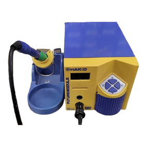
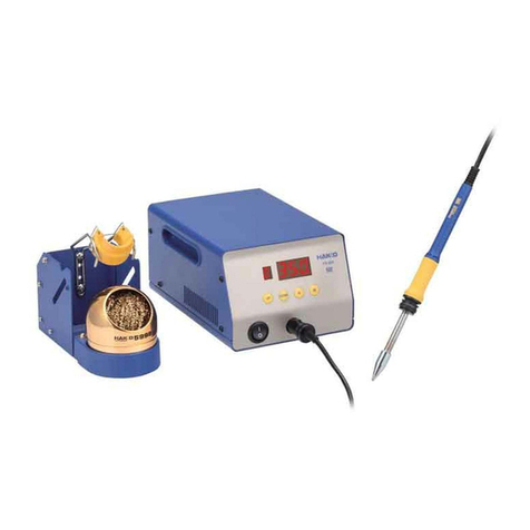
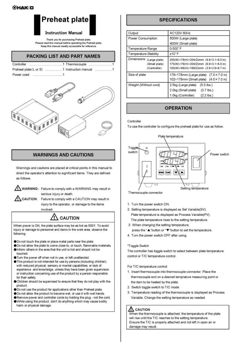
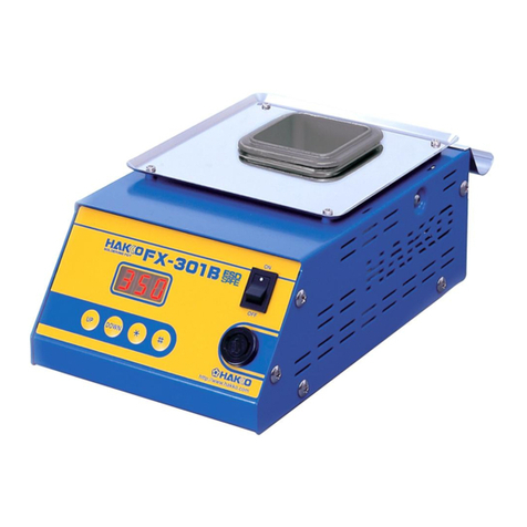
Other Hakko Electronics Soldering Gun manuals

Hakko Electronics FM-202 User manual

Hakko Electronics

Hakko Electronics FM-202 User manual

Hakko Electronics FX-951 User manual

Hakko Electronics

Hakko Electronics FX-951 User manual

Hakko Electronics FX-889 User manual

Hakko Electronics

Hakko Electronics FX-889 User manual

Hakko Electronics FX-952 User manual

Hakko Electronics

Hakko Electronics FX-952 User manual

Hakko Electronics HU-200 User manual

Hakko Electronics

Hakko Electronics HU-200 User manual

Hakko Electronics FX-301B User manual

Hakko Electronics

Hakko Electronics FX-301B User manual

Hakko Electronics FX-100 User manual

Hakko Electronics

Hakko Electronics FX-100 User manual

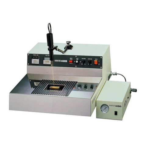
Hakko Electronics 485 User manual

Hakko Electronics

Hakko Electronics 485 User manual

Hakko Electronics FX-100 User manual

Hakko Electronics

Hakko Electronics FX-100 User manual

Hakko Electronics FR-803 User manual

Hakko Electronics

Hakko Electronics FR-803 User manual

Hakko Electronics FX-889 User manual

Hakko Electronics

Hakko Electronics FX-889 User manual

Hakko Electronics FR-300 User manual

Hakko Electronics

Hakko Electronics FR-300 User manual

Hakko Electronics FX-100 User manual

Hakko Electronics

Hakko Electronics FX-100 User manual

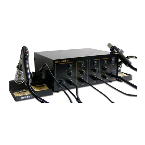
Hakko Electronics 702B User manual

Hakko Electronics

Hakko Electronics 702B User manual

Hakko Electronics FX-100 User manual

Hakko Electronics

Hakko Electronics FX-100 User manual

Hakko Electronics FX-100 User manual

Hakko Electronics

Hakko Electronics FX-100 User manual

Hakko Electronics FX-951 User manual

Hakko Electronics

Hakko Electronics FX-951 User manual

Hakko Electronics FX-8803 User manual

Hakko Electronics

Hakko Electronics FX-8803 User manual

Hakko Electronics 936 User manual

Hakko Electronics

Hakko Electronics 936 User manual

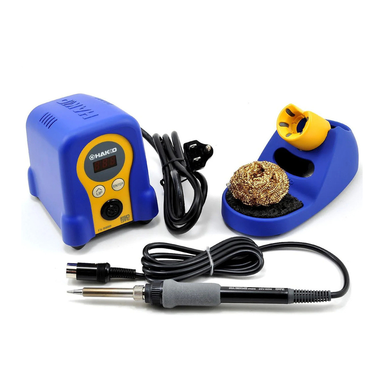
Hakko Electronics FX-888D User manual

Hakko Electronics

Hakko Electronics FX-888D User manual

Hakko Electronics FX?801 User manual

Hakko Electronics

Hakko Electronics FX?801 User manual

Hakko Electronics FM-203 User manual

Hakko Electronics

Hakko Electronics FM-203 User manual

Hakko Electronics 926 User manual

Hakko Electronics

Hakko Electronics 926 User manual

Hakko Electronics FX?801 User manual

Hakko Electronics

Hakko Electronics FX?801 User manual

Popular Soldering Gun manuals by other brands

FTM Technologies SI1R user manual

FTM Technologies

FTM Technologies SI1R user manual

Pace ST35 w/PS-90 Iron Operation and maintenance manual

Pace

Pace ST35 w/PS-90 Iron Operation and maintenance manual

Bakon 3200 instruction manual

Bakon

Bakon 3200 instruction manual

Proxxon Gaslotset MGS manual

Proxxon

Proxxon Gaslotset MGS manual

jbc SFR-A instruction manual

jbc

jbc SFR-A instruction manual

jbc CL8010 instruction manual

jbc

jbc CL8010 instruction manual

HAKO FX-8804 instruction manual

HAKO

HAKO FX-8804 instruction manual

SATA 02002A user manual

SATA

SATA 02002A user manual

Velleman HRJA151 user manual

Velleman

Velleman HRJA151 user manual

Weller WSM 1 operating instructions

Weller

Weller WSM 1 operating instructions

Vishay Precision Group Micro-Measurements Mark V Operating and maintaining

Vishay Precision Group

Vishay Precision Group Micro-Measurements Mark V Operating and maintaining

ersa i-CON 1V quick guide

ersa

ersa i-CON 1V quick guide

Atten ATETOOL AT-689A user manual

Atten

Atten ATETOOL AT-689A user manual

Surtek 112554 User manual and warranty

Surtek

Surtek 112554 User manual and warranty

Parkside PLBS 30 A1 Operation and safety notes

Parkside

Parkside PLBS 30 A1 Operation and safety notes

AlienTek T100 user manual

AlienTek

AlienTek T100 user manual

Weller FT12 operating instructions

Weller

Weller FT12 operating instructions

ersa RA 4500 D operating instructions

ersa

ersa RA 4500 D operating instructions

manuals.online logo
manuals.online logoBrands
  • About & Mission
  • Contact us
  • Privacy Policy
  • Terms and Conditions

Copyright 2025 Manuals.Online. All Rights Reserved.