4. OPERATION
7 8
First, plug the power cord into a grounded wall socket,
then open the rear panel of the unit and turn on the Circuit
Breaker.
Check the breaker switch by depressing the test button,
approximately once a month.
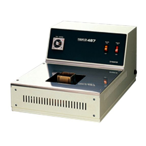
Turn on the power switch on the front panel, and set
key switch to MANUAL or AUTO. The unit will begin heating.
Adjust temperature (0-300℃, 32-570℉) with the temperature
control meter. When operating in AUTO, adjust the Digital
solder flow duration meter
(standard setting:250℃・482℉ 4sec.)
When temperature reaches the pre-set one, the temperature
control lamp turns from ▼to ■.
Shortly after, the “READY” lamp will turn on.
The unit is now ready to use.
Select the appropriate flow nozzle for your IC and fix it
to the solder flow outlet. Turn the locator light on and
set it to the center of the IC.
NOTE : As a safety feature, the locator light will not
operate until the temperature reaches the pre-set one,
regardless if the switch is turned on.
CAUTION
Mode - AUTO
Before selecting AUTO mode, turn the key switch to MANUAL.
Depress the foot switch and adjust the solder flow as desired
using the solder flow dial. Then turn the key switch to
AUTO mode.
Set the solder flow duration according to your needs.
Put a P.W.B. on the table, then set the locator light
to the center of the IC.
Depress the foot switch. Watch carefully to see when
the solder has become molten. At that time remove the IC.
Should it not remove easily, depress the foot switch once
more. The solder will flow only for the duration set on the
flow timer.
Connect the HAKKO 486(AIR UNIT) to the unit with 3P
metal connector. Turn the AIR UNIT switch to ON in order
to prepare for cleaning. Next, switch the MODE key on
the unit to AUTO, then, using a P.W.B. to test, set the solder
flow duration according to your needs.
Adjust Slow down control dial, Air pressure dial, Air blow
duration dial and Air blow timing dial.
Put a P.W.B. on the table and set the locator light where
the IC had been. Then place the hood of the air cleaning
hose over the section to be cleaned and lightly depress
the foot switch. Be especially careful not to press the P.W.B.
too much with your hands, as the solder will overflow through
the holes. After the solder has run out, compressed air from
the air hood cleans IC holes for the pre-set time period.
Other Uses
If an IC is defective or does not operate properly, it may
be replaced with a new IC. Remove defective IC, spray
flux on backside of board, and attach new IC using the
same procedure as above.
Excessive solder on the leads of the IC or other components
can be removed easily. Depress the foot switch and briefly
dip the leads into the solder bath.
It is also possible to attach various sized connects by
special ordering separate nozzle attachments from us.
NOTE :
After finishing the work, turn off the power switch.
Mode - MANUAL
Compressed air cleaning - after removal of IC
For safety reasons, be sure to ground the unit
by connecting the ground wire to a grounded terminal.
NOTE :
Without setting the key switch
to MANUAL or AUTO, the heater
will not begin heating.
Turn the key switch to MANUAL mode.
Depress the foot switch and adjust the solder flow as
desired using the solder flow dial.
Put a P.W.B. on the table, and set locator light to
the center of IC.
Depress the foot switch. Watch carefully to see when
the solder has become molten. At that time remove the IC.
NOTE :
As solder continues to flow while the foot switch
is depressed, remove your foot from switch just before
removing IC from the table.
An inter-locking device prevents the motor, the foot switch,
and the locator lamp from operating until the “READY”
lamp is lit.
