longer than the set value on the
TIMEIDIV.
switch. It
should be turned to the left to an adequately greater time
coefficient.
The signal to be displayed should be fed to the vertical input
of the oscilloscope by means of a shielded test cable, e.g.
the HZ32 or HZ34, or by a x 10 or x 100 attenuator probe.
The use of these shielded cables with high impedance cir-
cuits is only recommended for relatively low frequencies
(up to approx. 50kHz). For higher frequencies, and when
the signal source is of low impedance, a cable of matched
characteristic impedance (usually
5OQ)
is recommended.
In addition, and especially when investigating square or
pulse waveforms, a resistor equivalent to the characteristic
impedance of the cable must also be connected to the cable
directly at the input of the oscilloscope. When using a 509
cable, such as the HZ34, a
50R
through-termination type
HZ22 is available from HAMEG. When investigating square
or pulse waveforms with fast risetimes, transient
phenomena on both the edge and top of the signal may be-
come visible if the correct termination is not used. It must
be remembered that the
5OQ
through-termination will only
dissipate a maximum of 2 watts. This power consumption
is reached with 1
OV,,,
or with
28V,,
sine signal.
If a x 10 or x 100 attenuator probe is used, no termination is
necessary. In this case, the connecting cable is matched di-
rectly to the high impedance input of the oscilloscope.
When using attenuator probes even high internal imped-
ance sources are only slightly loaded by approximately
10
MQ
I I 16
pF
or 100
MQ
I I7
pF
respectively. Therefore,
when the voltage loss due to the attenuation of the probe
can be compensated by a higher sensitivity setting on the
HM 604, the probe should always be used. Also it should be
remembered that the series impedance of the probe pro-
vides a certain amount of protection for the input of the os-
cilloscope amplifier. It should be noted that all attenuator
probes must be compensated in conjunction with the oscil-
loscope (see: Probe Adjustment, page M8).
If a x IO or x 100 attenuator probe is used at voltages
higher than 400 V, the DC input coupling must always
be set. With AC coupling, the attenuation is frequency-de-
pendent, the pulses displayed can exhibit ramp-off, DC-volt-
age contents are suppressed
-
but loads the respective
input coupling capacitor of the oscilloscope. The electric
strength of which is maximum 400V (DC + peak AC). For
the suppression of unwanted DC voltages, a capacitor of
adequate capacitance and electric strength may be con-
nected before the input tip of the probe (e.g. for ripple
measurements).
It is important to remember that when low voltage signals
are being investigated the position of the ground point on
the test circuit can be critical. This ground point should al-
ways be located as close as possible to the measuring
point. If this is not done, serious signal deformation may
result from any spurious currents through the ground leads
or test chassis parts. This comment also applies to the
ground leads on attenuator probes which ideally should be
as short and as thick as possible. For connection of a probe
to a BNC socket, a BNC-adapter should be used. It forms
often a part of the probe accessory. Grounding and match-
ing problems are then eliminated.
Hum or interference voltage appearing in the measuring cir-
cuit (especially with a small deflection coefficient) is possi-
bly caused by multiple grounding, because equalizing cur-
rents can flow in the shielding of the measuring cables (volt-
age drop between non-fused earthed conductors of other
line powered devices, which are connected to the oscillo-
scope or test object, e.g. signal generators with anti-inter-
ference capacitors).
Operating
For a better understanding of these Operating Instructions
the front panel picture at the end of these instructions can
be unfolded for reference alongside the text.
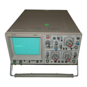
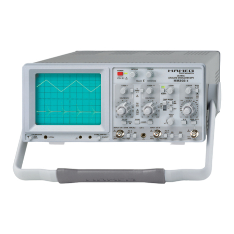
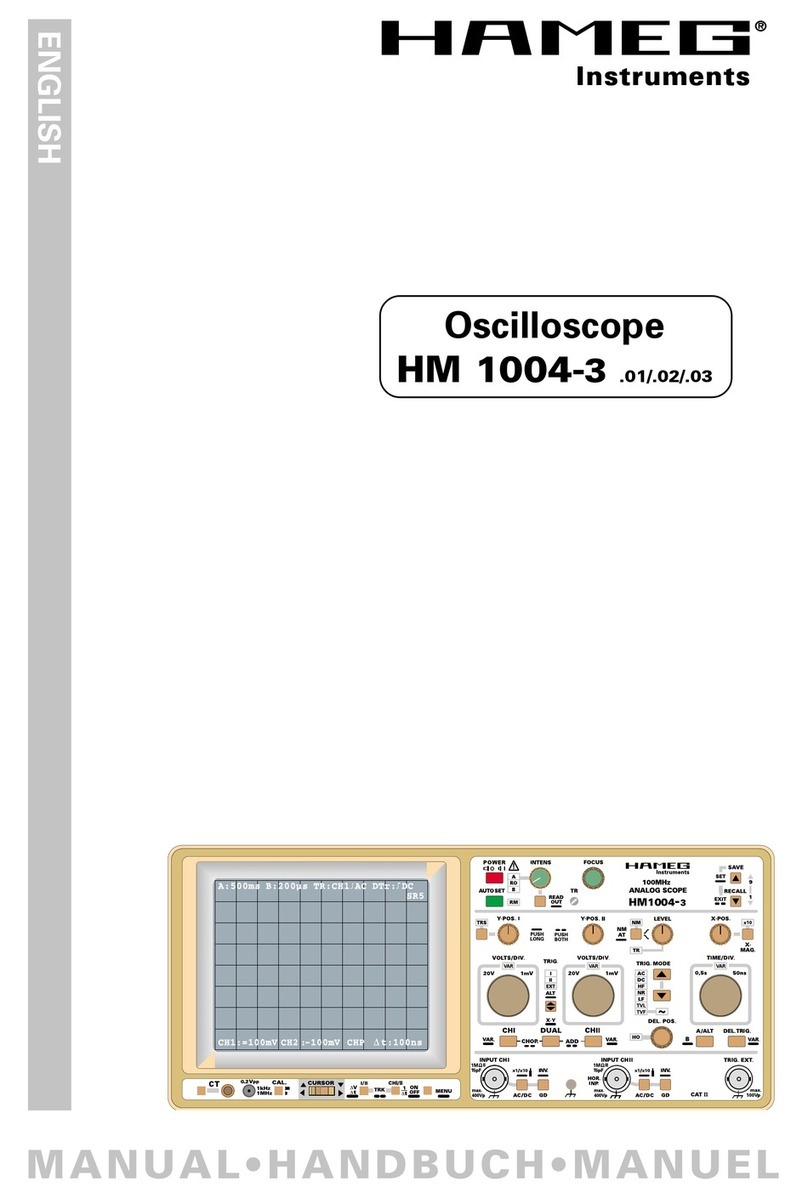
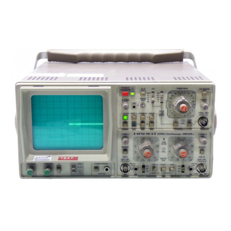
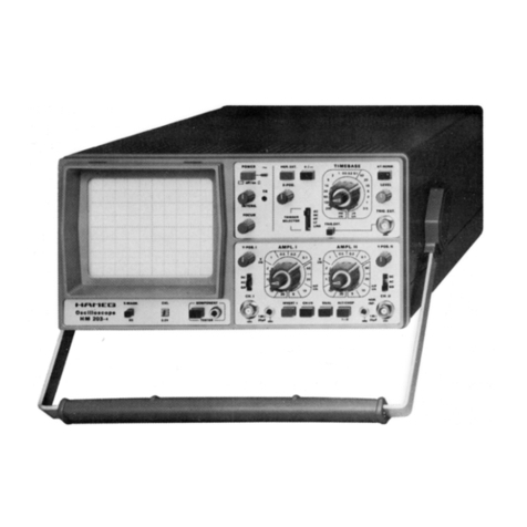
The front panel is subdivided into three sections according
to the various functions. The INTENS., FOCUS and TR
(trace rotation) controls are arranged on the left directly
below the screen of the cathode-ray tube (CRT). Continuing
towards the right are the horizontal magnification button (X
MAG. x10), the switch for calibrator frequency selection
(1
kHz/l
MHz) and calibrator output sockets
0.2V/2V
(CAL.). The COMPONENT TESTER pushbutton and its
measuring socket are located on the right side.
The X-Section, located on the upper right, next to the screen,
contains the red POWER pushbutton and indicating LED, all
controls for
timebase
(TIME/DIV.),
triggering (TRIG.), hori-
zontal trace position (X-POS.), sweep delay (DELAY), TV
separator (TV SEP.) together with the field select button
(FIELD
l/II),
the XYmode button (XV), and the knob for
hol-
doff adjustment (HOLD OFF).
The lower Y-Section contains the controls for the vertical
deflection system. On the right and left in this section are lo-
cated: vertical input connector, DC-AC-GD input coupling
slide switch, Y-POS. control, INVERT pushbutton, at-
tenuator switch with variable control, and ground jack. All
these controls and connectors exist in duplicate for each of
the Channels I and II. Three pushbuttons for selecting the
operating mode are arranged below the attenuator
switches: CH
l/II
-TRIG l/II, DUAL and ADD.
These are explained later.
The instrument is so designed that even incorrect operation
will not cause serious damage. The pushbuttons control
only minor functions, and it is recommended that before
commencement of operation all pushbuttons are in the
“out” position. After this the pushbuttons can be operated
depending upon the mode of operation required.
M6 604 Subject to change without notice
