H&S BW1000 LINEWRAP BW1000 LINEWRAP User manual

Manufactured By
H&S MANUFACTURING CO.,INC.
P.O. BOX 768 (715) 387-3414 FAX (715) 384-5463
MARSHFIELD, WISCONSIN 54449
WARNING
HSMFG0414 Part#59665
Revision#03
StartingSerial#412271
READ AND UNDERSTAND THIS MANUAL
BEFORE OPERATING THIS EQUIPMENT.
UNSAFE OPERATION OR MAINTENANCE OF
THIS EQUIPMENT CAN RESULT IN SERIOUS
INJURY OR DEATH.
BW1000 LINEWRAPBW1000 LINEWRAP
BW1000 LINEWRAP
OPERAOPERA
OPERAOPERA
OPERATT
TT
TOR’S MANUOR’S MANU
OR’S MANUOR’S MANU
OR’S MANUALAL
ALAL
AL

CONTENTS
Warranty &Warranty Registration Card . . . .. . . .. . . . . . .. . . .. . . . . . .. . . .. . . .. . . . . . .. . . .. . 1-2
ManufacturersStatement. . .. . . .. . . .. . . . . . . . . . .. . . .. . . .. . . .. . . . . . .. . . .. . . .. . .. . .. . . . . . 2
DealerPre-Delivery Checklist . . . .. . . . . .. . . . . . . . . . . . . . . . . . . . . . . . . . . . .. . . . . .. . . . . . . . . . . . 3
DealerDelivery Checklist . . . . . . .. . . .. . . . . . . . .. . . . . . . . .. . . . . . . . .. . . . . . . . .. . . .. . . . . . . . .. 5
SafetyInformation - BeAlertSymbol. . . . .. . .. . .. . .. . .. . . . .. . .. . .. . .. . . . . . . .. . .. . ... .. . .. 7
SafetyInformation -Explanation of Safety Signs .. .. . . . .. .. . . . .. .. . . . .. .. . . . .. .. . . . .. .. .. .8
SafetyDecals . . . . . . . . . .. . . . . . . . . . . . . . . .. . . . . . . . . . .. . . . . . . . . . .. . . . . . . . . . . . . . . .. . . . 9-10
SafetyInformation-Warning -OwnerMust Read andUnderstand .... .... ... . ... .... ... . .11-12
CapScrew TorqueValues. . .. . .. . .. . .. . .. . .. . .. . .. . .. . .. . .. . .. . .. . .. . .. . .. . .. .. . .. . .. 13
Set-Up&Assembly.. . . . . .. . . . . . .. . .. . . . . . .. . . . . . .. . . .. . . . . . .. . . . . . .. . .. . .. . . . . . .. . . 14
Transporting. . . . .. . .. .. . .. . . . .. . .. . . . .. . .. .. . .. . . . .. . .. . . . .. . .. .. . .. .. . . . .. . .. .. . .. . 15
Preparingfor Operation. .. . .. .. .. . . . .. .. . . . .. .. . . . .. .. . . . .. .. .. . .. .. .. . .. .. .. .. .. . . . ..16
Operation. . .. . .. . .. . . . . . . . . .. . .. . .. . .. . .. . . . . . . . . .. . .. . .. . .. . . . . . . . .. . .. . . . . . . . . 17-22
Service&Adjustments. . . . . . .. . .. . .. . .. . .. . .. . .. . . . . . . . . . .. . .. . .. . .. . .. . .. .. . . . .. . 23-24
OptionalEquipment .. .. .. . . . .. .. .. . . . .. .. .. .. . . . .. .. .. . . . .. .. .. .. . . . .. .. .. .. . . . .. .. .. 25
LubricationGuide . .. . .. . . . . . .. . .. . .. . . . . . .. . .. . .. . . . . . .. . .. . .. . . . . . .. . .. . .. . . . . . . 26-27
Decal Location . . . . .. . . . . . .. . . . . . .. . . . . . .. . . . . . .. . . . . . .. . . . . .. . . . . . .. . . . . . . .. . . . . 28-30
Troubleshooting. .. . .. .. . . . .. . . . .. .. . .. .. . . . .. .. . .. .. . . . .. . . . .. .. . .. .. . . . .. . .. .. . . 31-33
ServiceNotes .. . . . .. . . . .. .. . .. .. . . . .. .. . .. .. . . . .. . . . .. .. . .. .. . . . .. .. . .. . .. .. . . . .. . . . 34
Specifications ....... ....... . ....... . ....... ....... . ....... . ...... . ...... . InsideBackCover


LINEWRAP was not damaged in shipment. Check for dents and loose or missing
parts. Report damage immediately to H&S Manufacturing Co., Inc.
LINEWRAP has been correctly assembled according to instructions in this manual.
All bolts and fasteners are tight.
All Shields and Guards are in place and fastened.
All grease fittings have been lubricated. See Lubrication Chapter of this manual for
details.
Hoses and fittings are properly attached and there are no visible leaks.
All mechanisms are operating trouble free.
Hydraulic fluid reservoir is filled to proper level.
Wheels are properly mounted and wheel nuts are tightly secured.
Tires are inflated to correct pressure.
Decals are in place and legible.
After the LINEWRAP has been completely set-up, check to be certain it is in correct operating order
before delivering to the customer. The following is a list of points to inspect. Check off each item as
you have made the proper adjustments and found the item operating satisfactorily.
Serial Number
Dealer’s Name
Signature of Pre-Delivery Inspector
-3-
(Remove Dealers File Copy At Perforation)
DEALER PRE-DELIVERYCHECK LIST
AFTER COMPLETION, DEALER SHOULD REMOVE AND RETAIN FOR RECORDS
Inspection Date
ModelNumber

IntentionallyLeftBlank
-4-

DEALER DELIVERYCHECK LIST
AFTER COMPLETION, DEALER SHOULD REMOVEAND RETAIN FOR RECORDS
Thischecklistthatfollows is an important reminder of valuableinformationthatshouldbepassed
on to the customer at the time that this Machine is delivered.
Check off each item as you explain it to the customer.
This delivery check list, when properly filled out and signed assures the customer that the
Pre-delivery service was satisfactorily performed.
Explain to the customer that the pre-delivery inspection was made.
Explain to the customer all the safety precautions they must exercise when operating
this unit.
Explain the recommended settings for different types of bales.
Explaintocustomerthatregular lubrication is required for properoperationandlonglife of
machine.
Show customer the lubrication section of Owner’s Manual.
Give the customer Owner’s Manual and make sure they read and understand all operating
and service instructions.
Have the customer sign a completed “Warranty Registration”, and mail it.
Date Delivered
Dealer’s Name
By
Signature of Original Buyer
Note: Warranty is not valid until warranty card is completed and returned to H&S Mfg. Co., Inc.
-5-
(Remove Dealers File Copy At Perforation)

-6-
IntentionallyLeftBlank

-7-
BE
ALERT! YOURSAFETY
ISINVOLVED.
THIS SYMBOL IS USED THROUGHOUT THIS BOOK WHENEVER YOUR PERSONAL SAFETY
IS INVOLVED. TAKE TIME TO BE CAREFUL. REMEMBER: THE CAREFUL OPERATOR IS THE
BEST OPERATOR. MOST ACCIDENTS ARE CAUSED BY HUMAN ERROR. CERTAIN
PRECAUTIONS MUST BE OBSERVED TO PREVENT THE POSSIBILITY OF INJURY OR
DAMAGE.
SAFETYINFORMATION
H&S MANUFACTURING CO., INC.

-8-
RECOGNIZE SAFETY INFORMATION
This is the safety-alert symbol. When you see this
symbol on your machine or in this manual, be alert to the
potential for personal injury.
Follow recommended precautions and safe operating
practices.
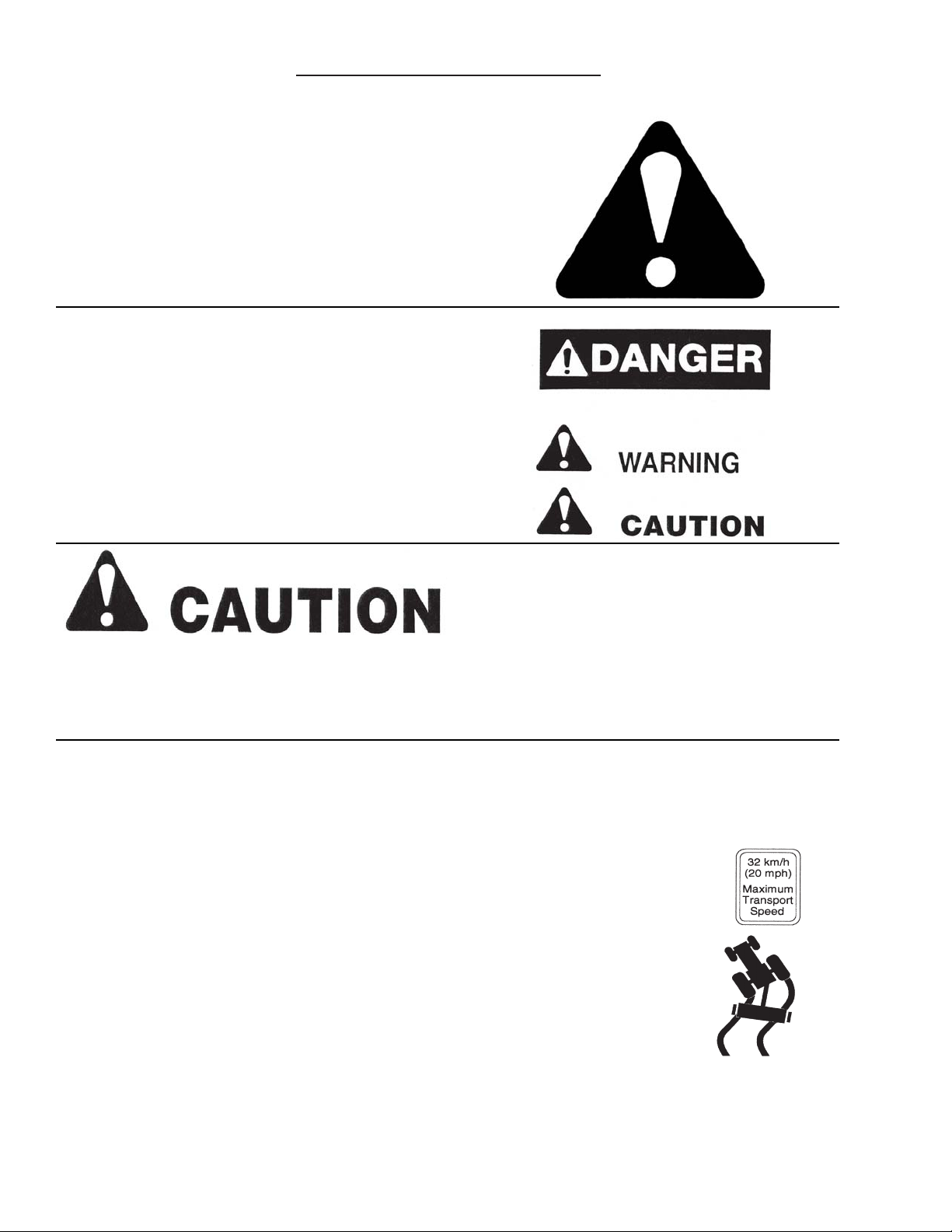
UNDERSTAND SIGNAL WORDS
A single word; DANGER, WARNING, or CAUTION is used
with the safety-alert symbol. DANGER identifies the most
serious hazards.
Safety signs with signal word DANGER or WARNING are
typically near specific hazards.
General precautions are listed on CAUTION safety signs.
FOLLOW SAFETY INSTRUCTIONS
Carefully read all safety messages in this manual, and all safety signs on your machine. Follow all
recommended precautions and safe operating procedures.
SAFETYINFORMATION
OBSERVE MAXIMUM TRANSPORT SPEED
The maximum transport speed for this implement is 32 km/h (20 m.p.h.).
Some tractors are capable of operating at speeds that exceed the maximum
transport speed of this implement. Regardless of the maximum speed capability
of the tractor being used to tow this implement, do not exceed the implement’s
maximum transport speed.
Exceeding the implements maximum transport speed can result in:
* Loss of control of the tractor/implement combination
* Reduced or no ability to stop during braking
* Implement tire failure
* Damage to the implement structure or its components
Use additional caution and reduce speed when towing under adverse surface
conditions, when turning, and when on inclines.
Do not attempt transport if the fully loaded implement weighs more than 1.5 times
the weight of the tractor.
Keep signs in good condition. Immediately replace any missing or damaged signs.

SAFETYINFORMATION
-9-

SAFETYINFORMATION
-10-

-11-
Study The Above Safety Rules
ATTENTION - BEALERT - YOUR SAFETY IS INVOLVED
BEFORE YOU ATTEMPT TO OPERATE THIS EQUIPMENT, READ AND STUDY THE FOLLOWING
INFORMATION. IN ADDITION, MAKE SURE THAT EVERY INDIVIDUAL WHO OPERATES OR WORKS
WITH THIS EQUIPMENT, WHETHER FAMILY MEMBER OR EMPLOYEE, IS FAMILIAR WITH THESE
SAFETYPRECAUTIONS.
H&S always takes the operator and his safety into consideration and guards exposed moving parts for
their protection. However, some areas cannot be guarded or shielded in order to assure proper operation. In
addition,theoperatorsmanualanddecalsonthemachineitselfwarnyou of further danger and should be
read and observed closely.
TO PREVENT SERIOUS INJURY OR DEATH
WARNING
DO NOTALLOW PERSONNEL OTHER THAN THE QUALIFIED OPERATOR NEAR THE MACHINE.
Stop the machine, remove key, and allow all mechanisms to stop before cleaning, working, or adjusting
on machine.
BE SURE to read and understand engine owner/operator manual supplied with this machine.
PRIOR TO starting engine, check to make sure all guards are in place and all persons are clear of the
machine. DO NOT attempt to perform maintenance or repair with engine running.
ALWAYS shut engine completely off before extending or retracting last bale push off mechanism.
Machine may start unexpectedly.
CHECK EMERGENCY STOP mechanism frequently to insure that it is operating properly.
DO NOT step up on machine at any time.
DO NOT allow minors to operate or be near the machine.
Loose or floppy clothing should not be worn by the operator.
Stay clear of hydraulic lines, they may be under extreme pressure or heat.
ALWAYS engage the brake prior to operating the wrapper, retract the brake prior to transport.
NEVER tow the LINEWRAP at speeds over 20 m.p.h.
SAFETYINFORMATION

-12-
WARNING
TO PREVENT SERIOUS INJURY OR DEATH NEVER OPERATE THIS UNIT
UNLESS THE EMERGENCY STOP FUNCTIONS PROPERLY
Your H&S Linewrap is equipped with an
electric emergency stop switch.
This switch is activated by the stop
cable.Activating the emergency stop will
stop all functions of the machine. The
engine will continue to run.
If the optional remote handset is used, the
emergency stop may be activated by pressing
the emergency stop button in either theAutomatic
or Remote Modes.
SAFETYINFORMATION
IF THE EMERGENCY STOP IS TRIPPED DURING WRAPPING CYCLE, THE UNIT
MUST BE SWITCHED TO MANUAL OPERATION ON THE CONTROL PANEL. PRESS THE
START/RESET SWITCH, THEN PRESS AND HOLD THE MANUAL PUSHER AND HOOP
SWITCHES TO BEGIN WRAPPING AGAIN, WHILE HOLDING SWITCHES, SELECT
THE DESIRED MODE, AUTOMATIC OR REMOTE ON THE CONTROL BOX TO CONTINUE
NORMAL OPERATION.

-13-

SET-UP &ASSEMBLY
NOTE: Determine right or left side of the LINEWRAP by viewing it from the rear. If instructions or
parts lists call for hardened bolts, refer to bolt torque chart.
1. Assemble the LINEWRAP and check for proper assembly and adjustment. Make sure that all
bolts are tightened.
2. Attach the wheels with tires, using the lug nuts furnished and torque the mounting hardware to
80 ft./lbs. of torque. Check wheel bolts periodically thereafter.
3. Check tires and inflate to the recommended pressure. (11L x 15 to 36 pounds)
4. Check the hydraulic oil level of the reservoir tank. Fill to the full level if needed (See Lubrication
Chapter in This Manual).
5. Lubricate the LINEWRAP completely (See Lubrication Chapter in This Manual).
-14-

-15-
TRANSPORTING
TOWING ON HIGHWAY
Follow state and local regulations when towing farm equipment on public highways. Never tow the
LINEWRAP on a public highway at a speed greater than 20 m.p.h. (32 kph).
REFLECTORS
A SMV bracket, red and amber reflective safety decals are on the LINEWRAP for safety. Refer to the
Decal Placement Chapter for location.

-16-
1. The LINEWRAP is shipped with a dry battery.Acid must be added and the battery brought to a full
charge.
2. Fill the gas tank with gas and check the engine oil level, fill to full level if needed.
3. Start the engine, let it idle for a short period of time to warm up.
4. Release the tail/ramp hydraulic locking valve while keeping the manual lock bar connected.
5.Activate the hydraulic control lever to pressurize the tail/ramp system.
6. Disconnect the tail/ramp lock bar and rotate it
forward to the storage position.
7.Activate the hydraulic control lever to lower the tail/ramp.
Cycle the ramp up and down a few times to remove
any air pockets. Turn the wheel brake valve to the upright
or off position, lower the ramp and the wheel brake will set.
8. Turn the wheel brake valve to the straight or on position,
this will release the wheel brake. Raise the tail/ramp,
replace lock bar and close the tail/ramp hydraulic locking valve.
9. Activate the Start/Reset switch on the control box by pushing up and releasing. This switch must
always be activated before any functions of the control box will operate.
10. Place the Mode switch in the manual position and operate the functions of the wrapper.
11. Place the Mode switch in the automatic position and push the bale trip bar down in the front of the
machine to check for proper operation. When the pusher contacts the first electronic switch, the
hoop should engage, upon contact with the second switch, the hoop should stop and the pusher
return to the home position.
PREPARING FOR OPERATION
Hydraulic
Control
Lever
Start/Reset
Switch
Mode
Switch
ManualHoop Switch Pusher Switch
Tail/Ramp
Hydraulic
Locking
Valve
Note; Stand aside of the tail/ramp when disconnecting
the lockbar in case there is an air pocket in the system
that would allow the tail/ramp to fall back upon removal.

OPERATION
INSTALLING PLASTIC FILM
To install plastic film on the machine, shut off engine, and
open side shield on the engine side of machine. Rotate
the hoop upward by hand until the first pre-stretcher is
accessible. Note that there are two different ways to put
the roll on the machine as shown by the decal. The tack
sideofthefilmshouldalwaysbetothebalesideofthe film.
The tack side of the film can be on either side and can be
determined by folding the film together inside to inside or
outside to outside. Which ever side pulls apart harder is
the tack side of the film. With the film correctly mounted,
route the film through the pre-stretcher as shown in the
decal. Go the other side of the machine, open the shield
and repeat the process described above to install the
second roll of plastic film.
PLACING WRAPPER IN POSITION
If possible, place the LINEWRAP in a north/south facing direction. This will allow minimal freezing to the
bales in the winter as the sun works from east to west.After placing in position, shorten the tongue into
thesteeringpositionby lifting the spring loadedtelescopinglockpinand sliding the telescopingtonguein.
Once the tongue has been retracted, the tongue can be pinned to the hand crank or hydraulic steer
mechanism. Steering will enable the machine to be guided around contours or along fence lines.
BALE GUIDES
Adjust the bale guides so they are a couple of inches wider than the diameter of the size of bales to be
wrapped. These guides are used to keep the bales centered while wrapping. DO NOT load bales onto
the guides. Improper use of the guide may result in damage to the machine.Adjustment can be made by
removing 4 pins, 2 rear and 2 front, rotating the bale guides and replacing the pins.
Always shut engine
off before making
adjustments.
-17-

-18-
BALE RISERS - ROUND BALES
There are two risers at the front of the machine. All round bales must be wrapped with the riser in the
down position. These risers serve as a loading platform for round bales in the down position.
BALE RISERS - SQUARE BALES
Placing the risers in the up position, allows a square bale to be wrapped sideways. Be sure to remove
the spikes from the low position and pin them into the end of the risers after raising them. The automatic
start bar must be moved to the up position for square bales as shown below. Lift start bar and slide to
your right and rest on the higher section of the bracket. Remove hair pin from end hole and place in
second hole from the end of the rod. This will secure start bar in the up position. Start bar is now in
position to be activated by square bale when placed on the riser in the up position. Bales can also be
wrapped lengthwise with the installation of the optional Riser Shelf. When risers are lowered for round
bales, start bar must again be lowered.
OPERATION
Always shut engine
off before making
adjustments.
Table of contents
Other H&S Farm Equipment manuals

H&S
H&S 5226 User manual

H&S
H&S 4242 User manual

H&S
H&S 2958 User manual

H&S
H&S 6128 User manual

H&S
H&S H D 7+4 FEEDER BOX Installation and maintenance instructions

H&S
H&S LW1100 User manual

H&S
H&S GM 170 Installation and maintenance instructions

H&S
H&S 1236 User manual

H&S
H&S 2108 User manual

H&S
H&S HD 7+4 User manual