FIG.E
FIG.D
FIG.F
FIG.G
FIG.H
P.V.I.
P.V.I.
Émis
Par
NE PAS MODIFIER MANUELLEMENT
Échelle
FORMAT Modèle du Fichier:
A
FEUILLE DE 1
RE .
DATEAPPROBATION
DESSINÉ PAR:
ÉRIFIÉ PAR:
RESP ENG
DESSIN GÉNÉRÉ PAR ORDINATEUR
De (LBS)
APPROX.
POIDS
SONT EN POUCE
TOLÉRANCES APPLICABLES:
TOUTES LES DIMENSIONS
FRACTIONS DÉCIMALES ANGLES
1/32"
À MOINS D'INDICATIONS CONTRAIRES
.005
NE PAS CHANGER L'ÉCHELLE
Pascal Clément
.XXX
.01.XX
1:60 1
1
TYPE D'ASSEMBLAGE:
ENLE ER TOUTES LES ARRÊTES I ES
FINI:
Révision
Numéros
EST INTERDITE.PARTIEL OU TOTAL SANS LA PERMISSION ÉCRITE DE LA COMPAGNIE
TOUTES REPRODUCTIONS
Révision Description de la Révision
De
L' INFORMATION CONTENU DANS CE DESSIN EST LA PROPRIÉTÉ EXCLUSIVE DE
Date
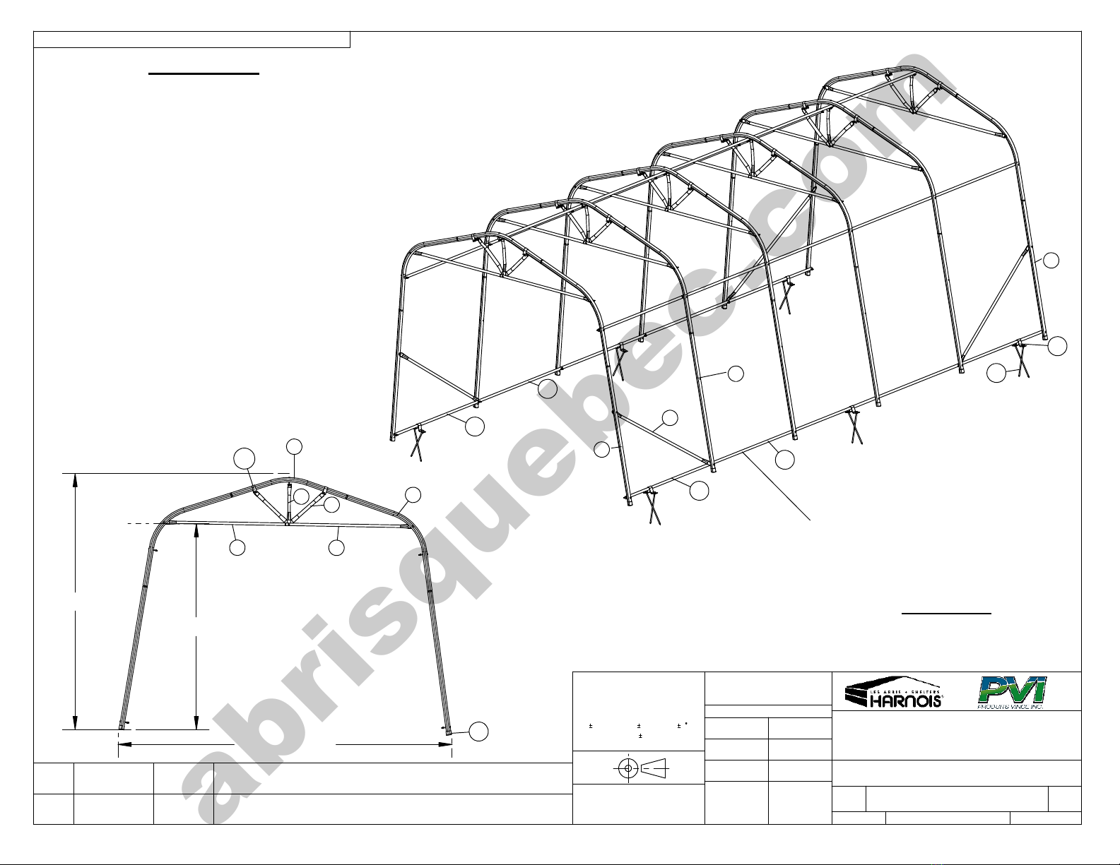
ÉRECTION DE LA STRUCTURE ET DE LA TOILE
STRUCTURE AND TARP ASSEMBLY
FIG.B
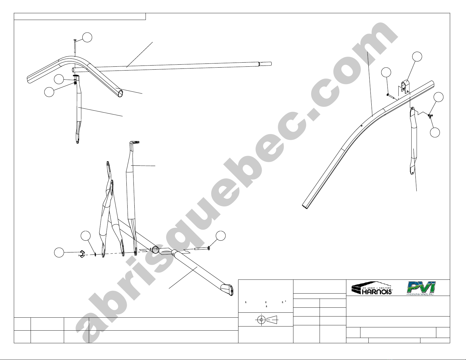
ERECTION DE LA STRUCTURE / STRUCTURE ASSEMBLY
X1
X2
X1 = X2
2
36
5
4
1
FIG.C
FIG. A
( SS ) = SIMPLE SHELTER
( DS ) = DOUBLE SHELTER
( AS ) = ABRI SIMPLE
( AD ) = ABRI DOUBLE
1. Assemble all arches on the groun making sure that you follow the positions shown (Fig. A)
Caution: Set the first arch with two #4 post 2 holes to secure the #9 (SS),#10 (DS) dia onals.
Caution: From 48’ to 60’ 6 posts with 2 holes and 6 dia onals.
2. Connect the base of the posts of the first arch with the base of the posts of the secon arch with two #10(SS), #11(DS)
swe ge brace male an secure the #10 iagonals at the base of the posts of the secon arch.
3. Lift the first arch an bolt the iagonals to the posts of the first arch.
4. Lift the secon arch an secure it to the first one by putting in place the swe ge braces.
5. To assemble the other arches, secure the base of the post of the last arch lifte with the base of the post of the next arch.
Lift it an secure them by putting in place the proper brace.
Caution: Always place the #11 (SS) ,#12 ( DS ) female braces between the second and third arch.
Important: All the win nuts must be ti hten and placed inside the shelter in order not to touch the cover.
6. Before putting the cover on, set the frame where you want it, a just the base wi th an set the frame square measuring
as shown (Fig. B). The two measurements must be the same.
Caution: If the structure is not perfectly square, the cover will be difficult to install and it could be dama ed durin the
installation.
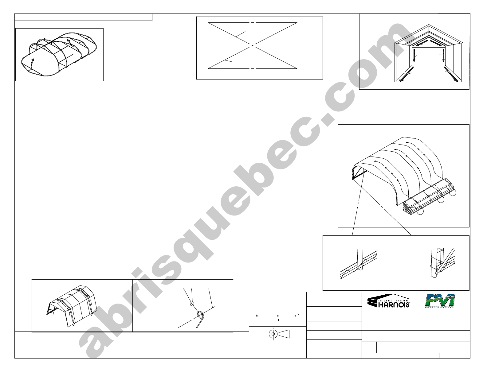
7. Carefully sli e the cover on top of the frame using ropes as shown (Fig. D)
8. Tie the cover to the frame with the supplie rope (Fig. C, D, E & F). Start at the center of both en s moving towar s the
si es. At the bottom, tie the cover to the base braces.
Important: Make sure that the cover is centered on the frame.
Important: The tarp must always be securely tied in order to avoid premature wear and tear.
9. Once the tarp is installe , anchor the shelter using the #18 (SS) #25 (DS) an #19 (SS), #26 (DS) items. AS IT IS
ILLUSTRATED FROM THE POINT OF VIEW OF GENERAL ASSEMBLY
10. Install the accessories following the instructions supplie with each items.
WARNING: WE STRONGLY RECOMMEND THE USE OF ‘’WINDSECURE KIT’’ (2T3800-A) TO HOLD YOUR SHELTER DOWN WHEN
EXPOSED TO STRONG WINDS. THIS ITEM IS SOLD SEPARATELY. SEE FIGURE ( G AND H ) . NEVER INSTALL A SHELTER WITHOUT
USING THE APPROPRIATE ANCHORS.