HBM DT85 User manual

A1704-3.3 en/de
Display and Control Unit
DT85
Operating Manual
Bedienungsanleitung
Anzeige und Bedieneinheit

English Page 3 −36. . . . . . . . . . . . . . . . . . . . . . . . . . . . . . . . . . . . . . . . . . . . . .
Deutsch Seite 37 −70. . . . . . . . . . . . . . . . . . . . . . . . . . . . . . . . . . . . . . . . . . . . .

3
DT85
A1704−3.3 en/de
Contents Page
Safety information 4. . . . . . . . . . . . . . . . . . . . . . . . . . . . . . . . . . . . . . . . . . . . . . .
1 Scope of supply 8. . . . . . . . . . . . . . . . . . . . . . . . . . . . . . . . . . . . . . . . . . . . .
2 Application notes 9. . . . . . . . . . . . . . . . . . . . . . . . . . . . . . . . . . . . . . . . . . . .
3 Panel mounting 9. . . . . . . . . . . . . . . . . . . . . . . . . . . . . . . . . . . . . . . . . . . . . .
4 Connecting the DT85 10. . . . . . . . . . . . . . . . . . . . . . . . . . . . . . . . . . . . . . . . .
4.1 Establish the measurement chain 11. . . . . . . . . . . . . . . . . . . . . . . . . . . .
4.2 Pin assignment 11. . . . . . . . . . . . . . . . . . . . . . . . . . . . . . . . . . . . . . . . . . .
5 Setup and operation 13. . . . . . . . . . . . . . . . . . . . . . . . . . . . . . . . . . . . . . . . . .
5.1 Set the baud rate 14. . . . . . . . . . . . . . . . . . . . . . . . . . . . . . . . . . . . . . . . . .
5.2 Displaybeleuchtung 15. . . . . . . . . . . . . . . . . . . . . . . . . . . . . . . . . . . . . . . .
5.3 Startup 16. . . . . . . . . . . . . . . . . . . . . . . . . . . . . . . . . . . . . . . . . . . . . . . . . . .
5.4 Operating philosophy 17. . . . . . . . . . . . . . . . . . . . . . . . . . . . . . . . . . . . . .
5.5 ZOOM function 19. . . . . . . . . . . . . . . . . . . . . . . . . . . . . . . . . . . . . . . . . . . .
5.6 Passcode query 19. . . . . . . . . . . . . . . . . . . . . . . . . . . . . . . . . . . . . . . . . . .
5.7 Overview of display readings 20. . . . . . . . . . . . . . . . . . . . . . . . . . . . . . . .
5.8 DT85 menu navigation 21. . . . . . . . . . . . . . . . . . . . . . . . . . . . . . . . . . . . .
6 Typical measurement mode displays 29. . . . . . . . . . . . . . . . . . . . . . . . . .
7 Explanations for the fundamental display parameters 31. . . . . . . . . . .
8 Explanation of the main setup parameters 33. . . . . . . . . . . . . . . . . . . . .
9 Error messages 35. . . . . . . . . . . . . . . . . . . . . . . . . . . . . . . . . . . . . . . . . . . . . .

4DT85
HBM A1704−3.3 en/de
Safety information
Appropriate use
The DT85 with its connected amplifiers must only be used for measurement
tasks and directly associated control tasks. Use for any purpose other than
the above shall be deemed to be inappropriate.
In the interests of safety, the device should only be operated as described in
the Operating Manual. It is also essential to observe the appropriate legal and
safety regulations for the application concerned during use. The same applies
to the use of accessories.
Each time, before starting up the equipment, you must first run a project
planning and risk analysis that takes into account all the safety aspects of
automation technology. This particularly concerns personal and machine
protection.
Additional safety precautions must be taken in plants where malfunctions
could cause major damage, loss of data or even personal injury. In the event
of a fault, these precautions establish safe operating conditions.
This can be done, for example, by mechanical interlocking, error signaling,
limit value switches, etc.
General dangers of failing to follow the safety instructions
The DT85 is a state of the art unit and as such is fail-safe. The device may
give rise to further dangers if it is inappropriately installed and operated by
untrained personnel.
Any person instructed to carry out installation, commissioning, maintenance or
repair of the device must have read and understood the Operating Manual
and in particular the technical safety instructions.
Conditions on site
Protect the devices from moisture or atmospheric influences such as rain,
snow, etc.
Maintenance and cleaning
The DT85 is maintenance−free. Please note the following points when
cleaning the housing:
−Before cleaning, disconnect the device from the power supply.
−Clean the housing with a soft, slightly damp (not wet!) cloth. You should
never use solvent, since this could damage the labeling on the front panel
and the display itself.
−When cleaning, ensure that no liquid gets into the device or the
connections.

5
DT85
HBM
A1704−3.3 en/de
Remaining dangers
The scope of supply and performance of the DT85 covers only a small area of
measurement technology. In addition, equipment planners, installers and
operators should plan, implement and respond to the safety engineering
considerations of measurement technology in such a way as to minimize
remaining dangers. Prevailing regulations must be complied with at all times.
There must be reference to the remaining dangers connected with
measurement technology.
Any risk of remaining dangers when working with the DT85 is pointed out in
these instructions by means of the following symbols:
Symbol: WARNING
Meaning: Dangerous situation
Warns of a potentially dangerous situation in which failure to comply with
safety requirements can lead to death or serious physical injury.
Symbol: CAUTION
Meaning: Potentially dangerous situation
Warns of a potentially dangerous situation in which failure to comply with
safety requirements could lead to damage to property and slight or moderate
physical injury.
Symbols for operating instructions and useful information:
Symbol: NOTE
Means that important information about the product or its handling is being
given.
Symbol:
Meaning: CE mark
The CE mark enables the manufacturer to guarantee that the product
complies with the requirements of the relevant EC directives (see Declaration
of Conformity at http://www.hbm.com/HBMdoc).

6DT85
HBM A1704−3.3 en/de
Working safely
Error messages must only be acknowledged once the cause of the error has
been eliminated and the danger no longer exists.
The device complies with the safety requirements of DIN EN 61010 Part 1
(VDE 0411 Part 1).
To ensure adequate immunity from interference, the bus lines must be
shielded cables.
The power supply connection cables always need to be shielded.
When connecting the cables (attaching and detaching terminals), action must
be taken to prevent electrostatic discharge which could damage the
electronics.
The DT85 must be operated on a safety extra−low voltage (supply voltage
18...30 V DC), which usually supplies power to one or more consumers within
a control cabinet.
Should the device be operated on a dc voltage network1), additional
precautions must be taken to discharge excess voltages.
The supply connection, as well as the signal and sense leads, must be
installed in such a way that electromagnetic interference does not adversely
affect device functionality (HBM recommendation: ”Greenline shielding
design”, downloadable from the Internet at http://www.hbm.com/Greenline).
Automation equipment and devices must be covered over in such a way that
adequate protection or locking against unintentional actuation is provided
(such as access checks, password protection, etc.).
When devices are working in a network, these networks must be designed in
such a way that malfunctions in individual nodes can be detected and shut
down.
Safety precautions must be taken both in terms of hardware and software, so
that a line break or other interruptions to signal transmission, such as via the
bus interfaces, do not cause undefined states or loss of data in the
automation device.
Conversions and modifications
The DT85 display must not be modified from the design or safety engineering
point of view except with our express agreement. Any modification shall
exclude all liability on our part for any damage resulting there from. In
particular, any repair or soldering work on motherboards is prohibited. When
exchanging complete modules, use only original parts from HBM.
1) Distribution system for electrical energy with greater spatial expansion (e.g. over a number of control
cabinets) that may even supply consumers with large nominal currents.

7
DT85
HBM
A1704−3.3 en/de
Qualified personnel
The equipment may be used by qualified personnel only; the specifications
and the special safety regulationsneed to be followed in all cases.
This means people who meet at least one of the three following requirements:
−Knowledge of the safety concepts of automation technology is a
requirement and as project personnel, you must be familiar with these
concepts.
−As automation plant operating personnel, you have been instructed how to
handle the machinery and are familiar with the operation of the equipment
and technologies described in this documentation.
−As commissioning engineers or service engineers, you have successfully
completed the training to qualify you to repair the automation systems.
You are also authorized to activate, to ground and label circuits and
equipment in accordance with safety engineering standards.
It is also essential to comply with the appropriate legal and safety regulations
for the application concerned during use. The same applies to the use of
accessories.
Qualified personnel means personel familiar with the installation, fitting,
start−up and operation of the product, and trained according to their job.
WARNING
The DT85 is a class−A device. The device may cause radiofrequency
emissions in residential, commercial and light industrial premises. In this case,
the user may be required to take proper precautions. This means, for
example, installing the device in an EMC−proof control cabinet or connecting
ferrite elements to the signal and supply lines.

8DT85
HBM A1704−3.3 en/de
1 Scope of supply
•DT85 display and control unit
•DT85 operating manual
•3−pin connector for the supply voltage
•Two 4−pin connectors for the CAN connection
Accessories (not included in scope of supply):
•Plug-in screw terminal, CAN and supply voltage for the MP85A and the
MP85ADP
•3-pin socket
Supplier : Phönix
Designation: MSTB 2.5/3 −ST5.08 Order no.: 1757022
•4-pin socket
Supplier : Phönix
Designation: MSTB 2.5/4 −ST5.08 Order no.: 1757035

9
DT85
HBM
A1704−3.3 en/de
2 Application notes
The DT85 is an add-on for the twin-channel MP85A and MP85ADP amplifiers
of the PME product family.
Most important applications of the DT85:
•Graphical representation of all measured values, evaluation windows and
press−fit curves with OK / NOK decision−making
•Displaying status information
•Viewing all the important MP85A settings
•Loading and storing parameter sets in/from flash or MMC memory
•Setting the most important parameters (e.g. tolerance windows) and
functions (sensor test)
•The DT85 is not suitable as a display for tolerance band mode, as an
evaluation criterion
NOTE
Measurement acquisition, analysis and curves/results storage
take place in the connected PME device. The DT85 serves as
a display and control unit.
3 Panel mounting
216
157
All dimensions in mm
30
30
30
9
36
M3x12
(8x)
8.9
Seel 1 mm
Eight screws (M3) are used for mounting the DT85 in the panel housing.
10 DT85
HBM A1704−3.3 en/de
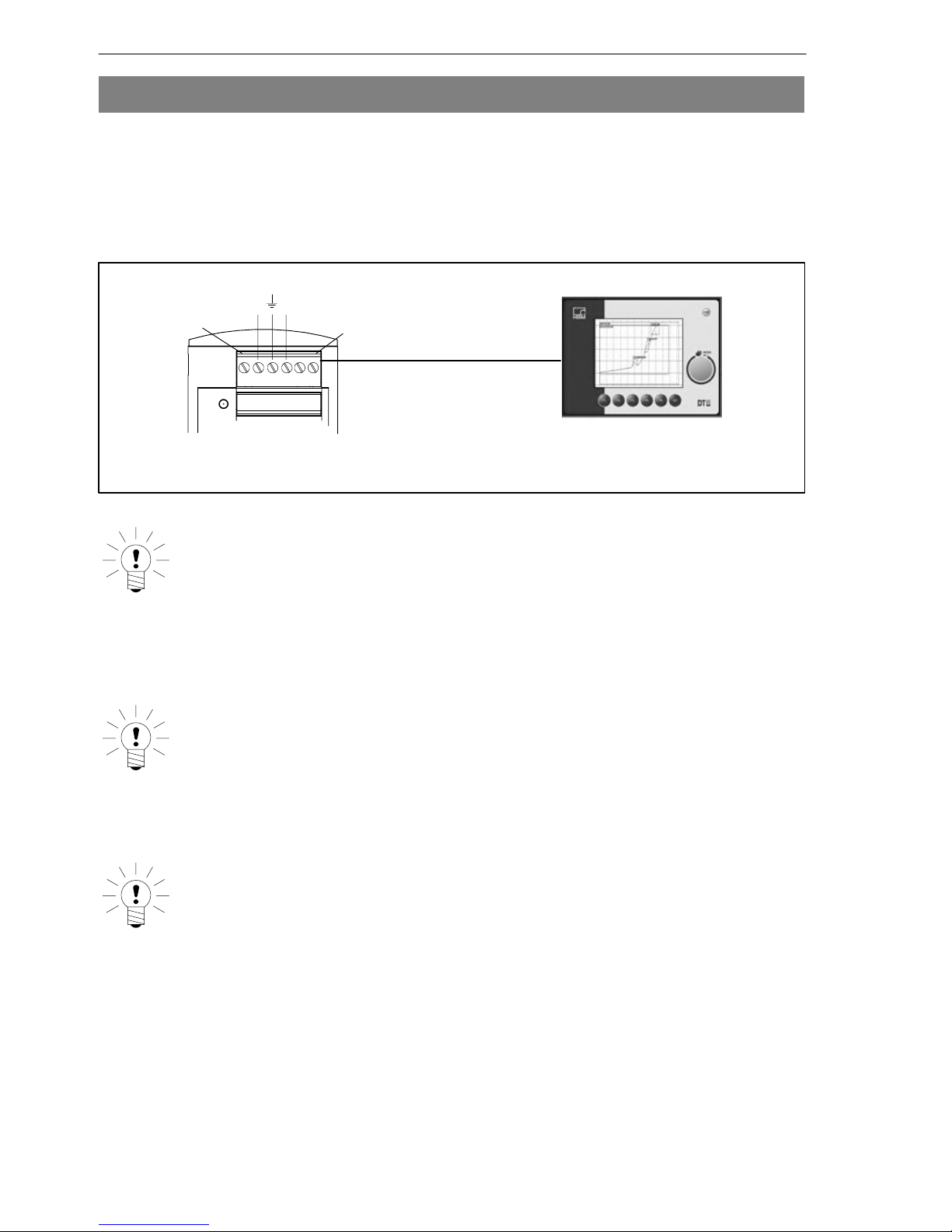
4 Connecting the DT85
Information is exchanged between the DT85 and the MP85A(DP) modules via
the CAN bus.
Up to 10 MP85A(DP) modules can be connected and parameterized. The
DT85 can be supplied with voltage via the screw terminal of the MP85A(DP)
module.
Voltage supply
and CAN
CAN−Low CAN−High
X 2
0V +UB
CAN−GND
Screw terminal 1 or 2
X 1
NOTE
The DT85 can be both connected to the MP85A(DP) module
and disconnected from the MP85A(DP) module while
measuring mode is running, without detriment. This also
applies to connecting a PC to the PME Assistant.
NOTE
A 120 Wtermination resistor has already been integrated into
the device.
NOTE
The DT85 operates as CAN master, the MP85A(DP) module as
CAN slave nodes. It is essential that all CAN slaves have
different CAN addresses. The address is set individually on
every MP85A module via the keys on the front.
Other manuals for DT85
1
Table of contents
Languages:
Other HBM Control Unit manuals


Popular Control Unit manuals by other brands

Festo
Festo Compact Performance CP-FB6-E Brief description

Elo TouchSystems
Elo TouchSystems DMS-SA19P-EXTME Quick installation guide

JS Automation
JS Automation MPC3034A user manual

JAUDT
JAUDT SW GII 6406 Series Translation of the original operating instructions

Spektrum
Spektrum Air Module System manual

BOC Edwards
BOC Edwards Q Series instruction manual

KHADAS
KHADAS BT Magic quick start

Etherma
Etherma eNEXHO-IL Assembly and operating instructions

PMFoundations
PMFoundations Attenuverter Assembly guide

GEA
GEA VARIVENT Operating instruction

Walther Systemtechnik
Walther Systemtechnik VMS-05 Assembly instructions

Altronix
Altronix LINQ8PD Installation and programming manual


