HBM MX403B User manual

English Deutsch Français
Voltage measurement module
1000V CAT II
600 V CAT III
MX403B
Operating Manual
A3757-1.0_en/de/fr

MX403B
2 A3757-1.0_en/de/fr
English
1 Introduction 3..............................................
2 Safety instructions 6........................................
2.1 Warning signs and danger symbols 6...........................
2.1.1 Symbols on the measurement module 7........................
2.2 Proper use 7................................................
2.3 Measurement categories 9....................................
2.4 Operating conditions 11.......................................
2.5 Maintenance, repair and modification 12.........................
2.6 Cleaning 13..................................................
2.7 Transportation, storage and disposal 14.........................
2.8 Qualified Personnel 15........................................
2.9 Working safely 15.............................................
2.10 System integration 19.........................................
3 Additional markings used 20.................................
4 Scope of delivery 21.........................................
5 Accessories 22..............................................
6 MX403B operation 24........................................
6.1 Preparatory measures and starting up 24........................
6.2 Connection/measurement 25...................................
6.3 Status Display 27.............................................
7 Specifications 28............................................

MX403B
A3757-1.0_en/de/fr 3
1 Introduction
QuantumX is a modular data acquisition system from
HBM for demanding measurement and test functions.
The different inputs acquire mechanical, electrical, hy
draulic and thermal measurands, such as force, strain,
torque, pressure, displacement, temperature, rotational
speed, acceleration, position, flow rate, voltage, etc.
The MX403B voltage measurement module can measure
voltages as high as 1000 V, as well as small differential
voltages at high electric potential.
The QuantumX family documentation basically com
prises:
SThe current operating manual for the voltage meas
urement module (available in printed form)
SA quick start guide for initial start-up (available in prin
ted form)
SData sheets for the individual modules and accessor
ies
SThe QuantumX operating manual with connection de
scriptions and possible system topologies and states
SThe operating manual for the EtherCAT1) / Ethernet
Gateway CX27
SThe operating manual for data recorder CX22-W /
CX22
SA comprehensive online help with index and easy
search options which is available after the installation
of a software package (e.g. QuantumX Assistant, cat
manEASY)
1) EtherCAT®is a registered brand and patented technology, licensed by Beckhoff Automation
GmbH, Germany

MX403B
4 A3757-1.0_en/de/fr
These documents can be found:
SOn the QuantumX system CD supplied with the device
SAfter installing the QuantumX Assistant on the hard
drive of your PC
SUp-to-date versions are always available from our In
ternet site at http://www.hbm.com/hbmdoc
Note
When working with the MX403B, always take note of the
standard operating manual (I2322) as well.
The high level of protection of the MX403B is guaranteed
by consistent development in accordance with the latest
conditions specified in the measuring equipment stand
ards IEC 61010-1:2010+Cor.:2011 and
IEC 61010-2-030:2010+Cor.:2011, as well as by VDE
certification and production monitoring.
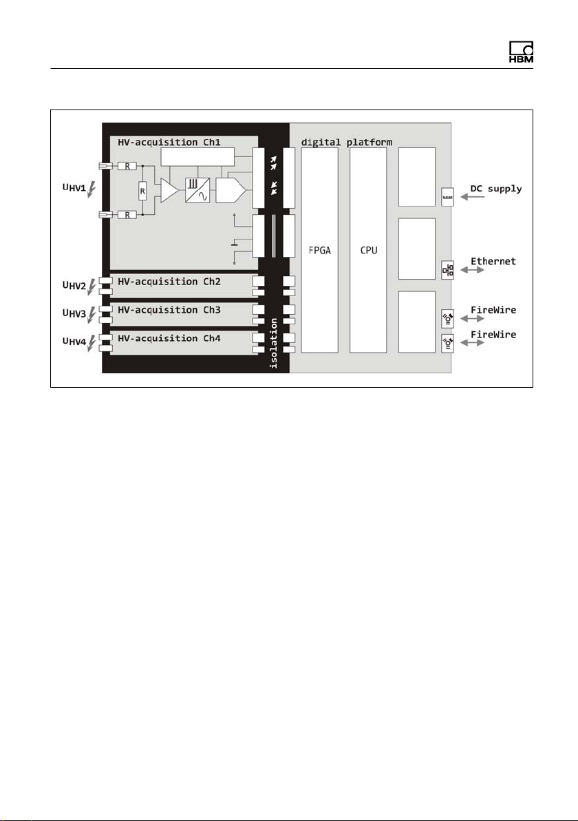
The MX403B has four insulated differential measurement
channels for directly measuring voltages up to 1000 V DC
or 1000 V rms AC.
The different measuring ranges allow the acquisition of
high voltages to remote ground, as well as the measure
ment of small differential voltages at high potential to re
mote ground.
The connection is made with 4 mm safety lab jacks,
19 mm pitch, suitable for standardized BNC adapters.
Each channel is equipped with a programmable amplifier,
analog reconstruction and antialiasing filters, a 24bit
ADC and digital filters.
MX403B
A3757-1.0_en/de/fr 5

MX403B
6 A3757-1.0_en/de/fr
2 Safety instructions
This measurement module is built and tested in accord
ance with EN 61010, Safety Requirements for Electrical
Equipment for Measurement, Control and Laboratory
Use, and was in perfect condition when it left production.
To maintain this condition and ensure risk-free operation
(reducing residual risks, EN 610101:2010 17 c), the user
must comply with the instructions and warning notices
contained in this operating manual.
2.1 Warning signs and danger symbols
Important instructions for your safety are specifically iden
tified. It is essential to follow these instructions in order to
prevent accidents and damage to property.
DANGER
This marking warns of an imminently threatening danger
ous situation which - if safety requirements are disregarded
- will result in death or serious physical injury.
Note
This marking draws attention to a situation which - if dis
regarded - can result in damage to property.

MX403B
A3757-1.0_en/de/fr 7
2.1.1 Symbols on the measurement module
Take details in the operating manual into account
Read and comply with the operating manual.
2.2 Proper use
The MX403B voltage measurement module fits perfectly
into the modular QuantumX series and is solely used to
measure high differential voltages or differential voltages
at high potential to remote ground, within the ratings
stated in the specifications.
The device is not intended for use as a safety compon
ent. Please also refer to the section: "Additional safety
precautions".
Proper and safe operation requires proper transportation,
correct storage, siting and mounting, and careful opera
tion.
Everyone involved with siting, starting up, or operating
the measurement module must have read and under
stood the operating manual and in particular the technical
safety instructions.
In the interests of safety, the measurement module
should only be operated by qualified personnel (see be
low) and as described in the operating manual. It is also
essential to comply with the legal and safety require
ments for the application concerned during use. The
same applies to the use of accessories.
MX403B
8 A3757-1.0_en/de/fr
DANGER
If the measurement module is not used as intended, the
protection provided by the measurement module may be
impaired.
DANGER
If the measurement module is used outside the ratings,
the protection provided by the measurement module may
be impaired.
MX403B
A3757-1.0_en/de/fr 9
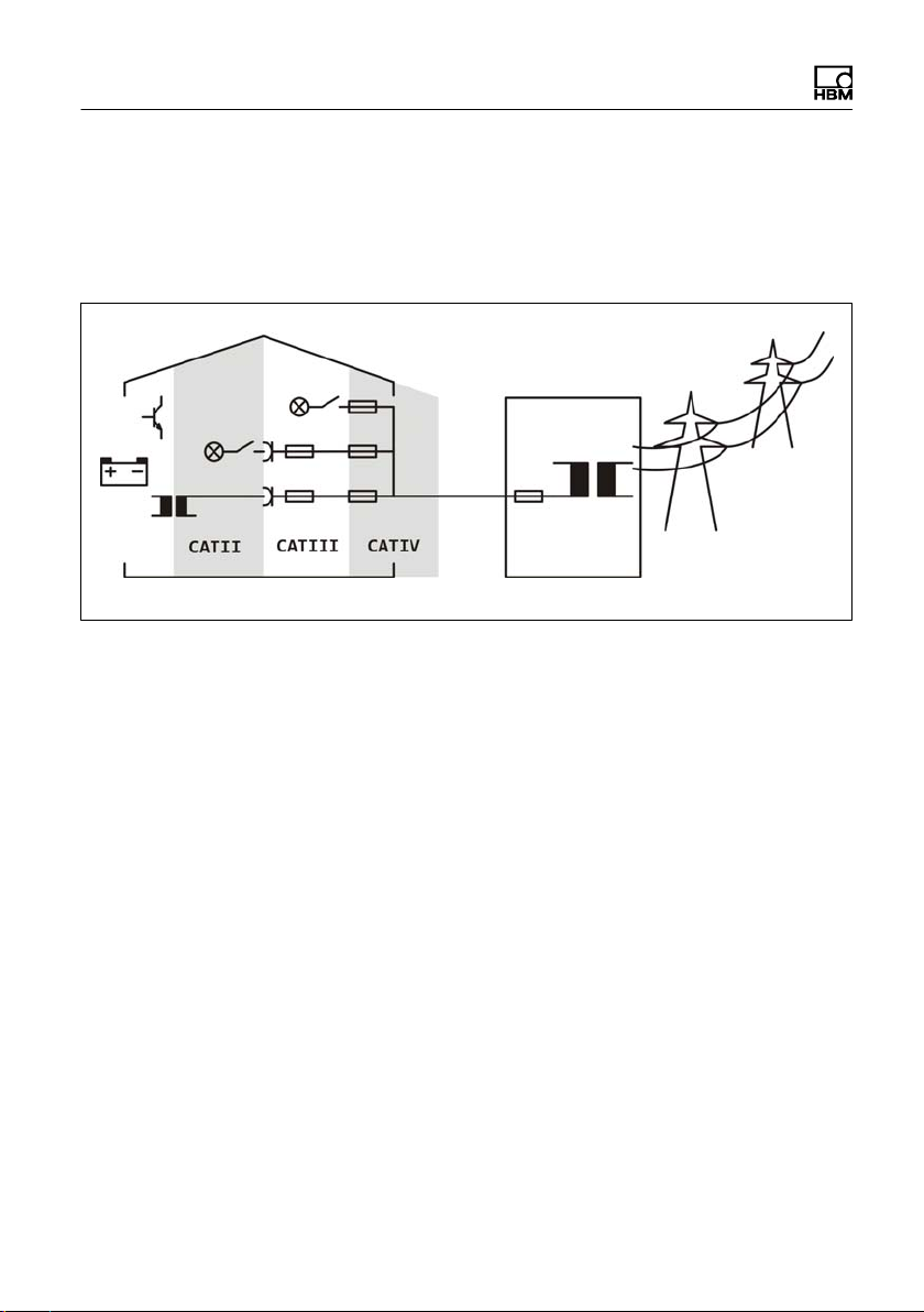
2.3 Measurement categories
The MX403B is designed for applications in measure
ment categories CAT II and CAT III:
CAT II
Measurement category II is applicable to test and meas
uring circuits that are directly connected to the user con
nections (sockets) of the low-voltage grid installation. It is
expected that this part of the installation will have at least
three levels with overload protection elements between
the transformer and the measuring circuit connection
point.
CAT III
Measurement category CAT III is applicable to test and
measuring circuits that are connected to the distribution
circuit of the building low-voltage grid installation. It is ex
pected that this part of the installation will have at least
two levels with overload protection elements between the
transformer and the measuring circuit connection point.
MX403B
10 A3757-1.0_en/de/fr
DANGER
For all other applications at the low-voltage installation
there is a risk related to:
SElectric shock
SArc flash burns
SArc blast explosion and
SOther phenomena
The MX403B is only suitable for rated voltages within the
measurement categories described - the MX403B is not
suitable for any other applications at the low-voltage in
stallation and its use here is not permitted.
Outside the measurement categories
The following applies to test and measuring circuits
without a rated measurement category (formerly CAT I):
Whether the MX403B is suitable for test or measuring
circuit applications not intended for direct connection to
the supply network can only be determined by an accur
ate analysis of the operating voltage, peak voltage, loop
impedance, occasional overvoltage and transient over
voltage of these circuits. The following characteristics
apply to the MX403B in this respect:
SPeak voltage: max. 1250 V
SLoop impedance: min. 100 m
(see EN 61010-2-030:2011 Table AA.1)
SOccasional overvoltage: none
STransient overvoltage: "3000 V
Table of contents
Languages:
Other HBM Control Unit manuals


Popular Control Unit manuals by other brands

Festo
Festo Compact Performance CP-FB6-E Brief description

Elo TouchSystems
Elo TouchSystems DMS-SA19P-EXTME Quick installation guide

JS Automation
JS Automation MPC3034A user manual

JAUDT
JAUDT SW GII 6406 Series Translation of the original operating instructions

Spektrum
Spektrum Air Module System manual

BOC Edwards
BOC Edwards Q Series instruction manual

KHADAS
KHADAS BT Magic quick start

Etherma
Etherma eNEXHO-IL Assembly and operating instructions

PMFoundations
PMFoundations Attenuverter Assembly guide

GEA
GEA VARIVENT Operating instruction

Walther Systemtechnik
Walther Systemtechnik VMS-05 Assembly instructions

Altronix
Altronix LINQ8PD Installation and programming manual


