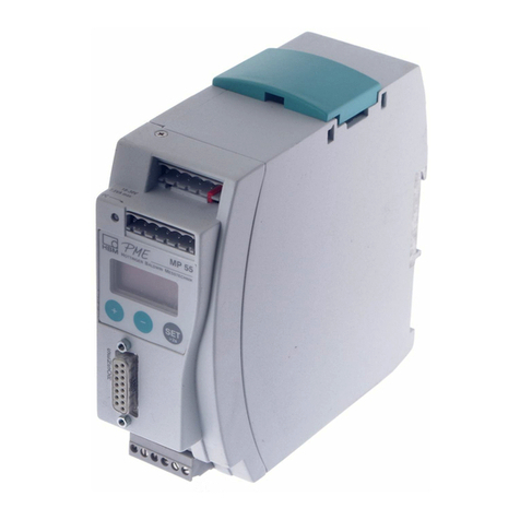
HBM MP55 User manual

A0563-7.2 en
PME industrial
measurement
electronics linked
to a field bus
MP55 module
Operating manual


3
PME-MP55
A0563-7.2 en HBM
Contents Page
Contents
Safety instructions 4. . . . . . . . . . . . . . . . . . . . . . . . . . . . . . . . . . . . . . . . . . . . . .
1 Introduction 9. . . . . . . . . . . . . . . . . . . . . . . . . . . . . . . . . . . . . . . . . . . . . . . . .
1.1 Scope of supply and accessories 9. . . . . . . . . . . . . . . . . . . . . . . . . .
1.2 General 9. . . . . . . . . . . . . . . . . . . . . . . . . . . . . . . . . . . . . . . . . . . . . . . .
2 Selecting amplifier settings with DIP switches 10. . . . . . . . . . . . . . . . . .
3 Mounting/dismountingMP55 14. . . . . . . . . . . . . . . . . . . . . . . . . . . . . . . . . .
3.1 Connecting several modules 15. . . . . . . . . . . . . . . . . . . . . . . . . . . . . .
4 Connection 16. . . . . . . . . . . . . . . . . . . . . . . . . . . . . . . . . . . . . . . . . . . . . . . . . .
4.1 Overview of MP55 functions 16. . . . . . . . . . . . . . . . . . . . . . . . . . . . . . .
4.2 Supply voltage and control inputs/outputs 17. . . . . . . . . . . . . . . . . . .
4.2.1 External supply voltage for control outputs 18. . . . . . . . . . . . .
4.3 Transducers 19. . . . . . . . . . . . . . . . . . . . . . . . . . . . . . . . . . . . . . . . . . . .
4.3.1 Connecting transducers in a four‐wire configuration 19. . . . .
4.3.2 Connecting transducers when cables are more than
50m long 20. . . . . . . . . . . . . . . . . . . . . . . . . . . . . . . . . . . . . . . . .
4.4 CAN interface 21. . . . . . . . . . . . . . . . . . . . . . . . . . . . . . . . . . . . . . . . . . .
4.5 Synchronization 22. . . . . . . . . . . . . . . . . . . . . . . . . . . . . . . . . . . . . . . . .
5 Setting and operating (MP55) 24. . . . . . . . . . . . . . . . . . . . . . . . . . . . . . . . .
5.1 Operating philosophy 24. . . . . . . . . . . . . . . . . . . . . . . . . . . . . . . . . . . . .
5.2 Starting up 27. . . . . . . . . . . . . . . . . . . . . . . . . . . . . . . . . . . . . . . . . . . . . .
5.3 Overview of all groups and parameters 28. . . . . . . . . . . . . . . . . . . . .
5.3.1 Setting all parameters 29. . . . . . . . . . . . . . . . . . . . . . . . . . . . . .
6 Clarification of important parameters 33. . . . . . . . . . . . . . . . . . . . . . . . . .
7 CAN interface description 41. . . . . . . . . . . . . . . . . . . . . . . . . . . . . . . . . . . .
7.1 General 41. . . . . . . . . . . . . . . . . . . . . . . . . . . . . . . . . . . . . . . . . . . . . . . .
7.2 Cyclic transmission of measured values 41. . . . . . . . . . . . . . . . . . . .
7.3 Parameterization 42. . . . . . . . . . . . . . . . . . . . . . . . . . . . . . . . . . . . . . . .
7.4 Object dictionary: Communication profile range in accordance
with CANopen (CiA‐DS301) 44. . . . . . . . . . . . . . . . . . . . . . . . . . . . . . .
7.5 Object dictionary: manufacturer‐specific objects 47. . . . . . . . . . . . . .
7.6 Manufacturer‐specific objects in FLOAT data format 56. . . . . . . . . .
7.7 Examples 58. . . . . . . . . . . . . . . . . . . . . . . . . . . . . . . . . . . . . . . . . . . . . . .
8 Error messages/operating state (LED) 60. . . . . . . . . . . . . . . . . . . . . . . . .
9 Index 63. . . . . . . . . . . . . . . . . . . . . . . . . . . . . . . . . . . . . . . . . . . . . . . . . . . . . . . .

PME-MP55
4
A0563-7.2 enHBM
Safety instructions
Before commissioning, make sure that the mains voltage and type of current
stated on the identification plate match the mains voltage and type of current
at the place of operation and that the circuit used is efficiently protected.
As the device does not have its own power switch, the supply cable
connected to it must not be directly applied to the mains supply. The
supply voltage must be 18 to 30 V. According the the VDE directive,
there must be a switching device present (such as a power switch) to
disconnect these devices from the mains. It is essential to ensure that
the device can be quickly disconnected from the mains supply at any
time.
The supply connection, as well as the signal and sense leads, must be
installed in such a way that electromagnetic interference does not adversely
affect device functionality (HBM recommendation: “Greenline shielding
design", downloadable from the Internet at http://www.hbm.com/Greenline).
Automation equipment and devices must be installed in such a way that ade
quate protection or locking against unintentional actuation is provided (e.g.
access checks, password protection, etc.).
When devices are working in a network, these networks must be designed in
such a way that malfunctions in individual nodes can be detected and shut
down.
Safety precautions must be taken both in terms of hardware and software, so
that a line break or other interruption to signal transmission, such as via the
bus interfaces, do not cause undefined states or loss of data in the automa
tion device.
Intended use
The MP55 module with connected transducers is to be used exclusively for
measurement tasks and directly related control tasks. Use for any purpose
other than the above is deemed to be non‐designated use.
In the interests of safety, the device should only be operated as described in
the Operating Manual. It is also essential to comply with the legal and safety
requirements for the application concerned during use. The same applies to
the use of accessories.
Each time, before starting up the equipment, you must first run a project
planning and risk analysis that takes into account all the safety aspects of

5
PME-MP55
A0563-7.2 en HBM
automation technology. This particularly concerns personal and machine
protection.
Additional safety precautions to establish safe operating conditions in the
event of a fault, must be taken in plants where malfunctions could cause
major damage, loss of data or even personal injury.
This can be done, for example, by error signaling, limit value switches,
mechanical interlocking, etc.
General dangers of failing to follow the safety instructions
The MP55 module is a state of the art unit and as such is failsafe. The device
may give rise to residual dangers if it is inappropriately installed and operated
by untrained personnel.
Any person instructed to carry out installation, commissioning, maintenance or
repair of the device must have read and understood the Operating Manual
and in particular the technical safety instructions.
Conditions at the place of installation
Protect the devices from moisture and dampness or weather such as rain,
snow, etc.
Do not expose the device to direct sunlight. Ensure that there is adequate
ventilation.
Maintenance and cleaning
The MP55 module is maintenance free. Please note the following points when
cleaning the housing:
- Before cleaning, disconnect the device from the power supply.
- Clean the housing with a soft, slightly damp (not wet!) cloth. You should
never use solvent, since this could damage the labeling on the front panel
and the display.
- When cleaning, ensure that no liquid gets into the device or connections.

PME-MP55
6
A0563-7.2 enHBM
Residual dangers
The scope of supply and performance of the MP55 covers only a small area
of measurement technology. In addition, equipment planners, installers and
operators should plan, implement and respond to the safety engineering
considerations of measurement technology in such a way as to minimize resi
dual dangers. On‐site regulations must be complied with at all times. There
must be reference to the residual dangers connected with measurement tech
nology.
Any risk of residual dangers when working with the MP55 is pointed out in
these instructions by means of the following symbols:
Symbol: WARNING
Meaning: Dangerous situation
Warns of a potentially dangerous situation in which failure to comply with
safety requirements can lead to death or serious physical injury.
Symbol: CAUTION
Meaning: Possibly dangerous situation
Warns of a potentially dangerous situation in which failure to comply with
safety requirements could lead to damage to property and slight or moderate
physical injury.
Symbol: NOTE
Means that important information about the product or its handling is being
provided.
Symbol:
Meaning: Statutory waste disposal mark
In accordance with national and local environmental protection and material
recovery and recycling regulations, old devices that can no longer be used
must be disposed of separately and not with normal household garbage. If
you need more information about waste disposal, please contact your local
authorities or the dealer from whom you purchased the product.

7
PME-MP55
A0563-7.2 en HBM
Symbol:
Meaning: CE mark
The CE mark enables the manufacturer to guarantee that the product com
plies with the requirements of the relevant EC directives (the Declaration of
Conformity can be found at http://www.hbm.com/HBMdoc).
Working safely
Error messages should only be acknowledged once the cause of the error is
removed and no further danger exists..
The device complies with the safety requirements of DIN EN 61010 Part 1
(VDE 0411 Part 1).
The device must be mounted on a support rail connected to grounded con
ductor potential. Both the support rail and the MP55/MP55DP module must be
free of paint, varnish and dirt at the point of installation.
To ensure adequate immunity from interference, the bus cables (CAN and for
MP55DP, Profibus DP) must be shielded, twisted‐pair lines. The transducer
cables must also be shielded. To ensure adequate immunity from interfe
rence, use only the Greenline shielding concept (place the shield of the trans
ducer cable onto the connector housing).
The cables of the MP55/MP55DP digital inputs and outputs that are used
should not be longer than 30 meters and should not exit the building in which
the system is located. Otherwise it will not be possible to ensure that the
device works perfectly. Strong magnetic fields or lightning strikes may have a
destructive effect.
When connecting cables (fitting and extracting terminals), measures must be
taken to prevent electrostatic discharge which could damage the electronics.
The MP55/MP55DP module must be operated with a separated extra‐low vol
tage (18 to 30 V DC supply voltage), which usually supplies one or more con
sumers within a control cabinet.
Should the device be operated on a DC voltage network1), additional precau
tions must be taken to discharge excess voltages.
1) Distribution system for electrical energy with greater physical expansion (over several control cabinets, for
example) that may also supply consumers with high nominal (rated) currents.

PME-MP55
8
A0563-7.2 enHBM
Conversions and modifications
The MP55 module must not be modified from the design or safety engineering
point of view except with our express agreement. Any modification shall
exclude all liability on our part for any damage resulting therefrom.
In particular, any repair or soldering work on motherboards is prohibited.
When exchanging complete modules, use only original parts from HBM.
The device is delivered from the factory with a fixed hardware and software
configuration. Changes can only be made within the possibilities documented
in the manuals.
Qualified personnel
This device is only to be installed and used by qualified personnel strictly in
accordance with the specifications and with the safety rules and regulations
which follow.
This includes people who meet at least one of the three following require
ments:
- Knowledge of the safety concepts of automation technology is a require
ment and as project personnel, you must be familiar with these concepts.
- As automation plant operating personnel, you have been instructed how to
handle the machinery. You are familiar with the operation of the equipment
and technologies described in this documentation.
- As commissioning engineers or service engineers, you have successfully
completed the training to qualify you to repair the automation systems.
You are also authorized to activate, ground and label circuits and equip
ment in accordance with safety engineering standards.
It is also essential to comply with the legal and safety requirements for the
application concerned during use. The same applies to the use of accesso
ries.
Qualified personnel means persons entrusted with siting, mounting, starting
up and operating the product, who possess the appropriate qualifications for
their function.

9
PME-MP55
A0563-7.2 en HBM
1 Introduction
1.1 Scope of supply and accessories
Scope of supply:
D1 MP55 module
D3 6‐pin plug terminals, coded
Order‐no.: 3.3312‐0427 (plug terminal 3);
3.3312‐0428 (plug terminal 4); 3.3312‐0426 (plug terminal 1)
DFlat ribbon cable female connector, 10‐pin
DExtra spring for enclosure assembly (included in the pack)
D1 MP55 module Operating Manual
Accessories:
D15‐pin Sub‐D plug for transducers, Order no.: 3.3312‐0182
DStandard flat ribbon cable, 10 pin, 1.27 mm pitch
1.2 General
The MP55 module from the PME product line is a carrier‐frequency amplifier
suitable for connecting force transducers, pressure transducers, torque trans
ducers, displacement transducers and load cells for a wide variety of techno
logies. The MP55 module is set up and parameterized via a keyboard and dis
play, or by using the PME Assistant. The PME Assistant provides a simple
user interface under MS‐Windows for parameterizing the modules (in the
“PME Assistant" Online Help).
μP
A
D
Intelligent signal
conditioning,
e.g. limit value switch
D
A
Keyboard
and display
MP55
Carrier frequency bridge
excitation voltage
Scalable
analog output
Control inputs and
control outputs
CANopen
interface
24 V
Electrically isolated
voltage supply
Profibus DP interface (for
MP55DP)
Fig. 1.1: Block diagram of the MP55 module

PME-MP55
10
A0563-7.2 enHBM
2 Selecting amplifier settings with DIP switches
NOTE
The DIP switches must be set or changed before mounting the PME.
The different settings are defined with the DIP switches and can be read out
over the display (see chapter 5.3). These are the settings for
bridge excitation voltage, measuring range, bridge type, analog output,
synchronization, bus termination resistor, edge steepness
To set the DIP switches, proceed as shown in Fig. 2.1.
S1/S2
S5
S10
S11
S12
Unscrew the
cover
1
2
Fig. 2.1: Open the housing, DIP switch positions
123456
Example:
means
ON
Fig. 2.2: Switch convention

11
PME-MP55
A0563-7.2 en HBM
ON ON
ON
Upper
board:
Lower
board:
S10
P11
123456123456
ON
123456
S10 S11 S12
ON ON
S2 S1
S12
123
ON
S5
1
2
3
5
4
6
1
2
3
5
4
6
1
2
3
5
4
6
ON ON ON
123456 123456
Synchronization Analog
output
Bridge
type
Analog output
Bridge
excitation
voltage
12 3456 123456
ON ON
S2 S1
The switch
positions must not be
changed!
Input
range
Bridge
excitation
voltage
Bridge
type
Input
range
Amplifier type
S10, S11 and
S12 and S5
S1 and S2
Factory settings:
WARNING
1
2
3

PME-MP55
12
A0563-7.2 enHBM
S11
123456
ON
S1
S2 S1
S12
Bridge type1)
Full bridge
Half bridge
LVDT
123456
ON
S12
123456
ON
123456
ON
123456
ON
123456
ON
Input range*) 2)
123456
ON
123456
ON
3 mV/V
50 mV/V
123456
ON
123456
ON
123456
ON
123456
ON
500 mV/V
S5
S1
S1
S12
S12
S1 S11
S1 S11
S1 S11
123456
ON
S2
Bridge excitation voltage3)
5 V
2.5 V
1 V
123456
ON
S11
1234 56
ON
123456
ON
123456
ON
123456
ON
Analog output4)
123456
ON
S11
123
ON
S5
"10 V
"20 mA
123456
ON
123
ON
123456
ON
4 - 20 mA
V
mA
S2 S11
S2 S11
S5
S11
S11
Factory settings:
see Tab. 1.1, on opposite page
Switch pos. I
Switch pos. II
Switch pos. III
Fig. 2.3: Setting the amplifier
1) Look/check in display under TRANSDUCER group, “Transd.typ" parameter; see page 25
2)) Look/check in display under TRANSDUCER group, “Input" parameter; see page 25
3) Look/check in display under TRANSDUCER group, “Excitation" parameter; see page 25
4) Look/check in display under ANALOG OUTPUT group, “UaMode" parameter; see page 25
*) mV/V values relate to 5 VUB(see table Tab. 1.1 on next page)

13
PME-MP55
A0563-7.2 en HBM
Synchronization
123456
ON
S10
123456
ON
Master
Slave
S10
S10
Fig. 2.4: Setting the amplifier (contd.)
Bus termination resistor
Toggle switch for the termination
resistor (also see page 22)
ON OFF
S14
Fig. 2.5: Switch for the CAN Bus termination resistor (basic diagram)
Bridge excitation voltage (V) Input range
(mV/V)
Switch position ISwitch position II Switch position III
5 3 50 500
2.5 6 100 1000
1 15 250 2500
Tab. 1.1: Input ranges for different bridge excitation voltages
Transducer type and nominal (rated)
data
Bridge type Bridge excitation
voltage
Input range
SG transducer 2 mV/V=20 kN Full bridge 5 V 3 mV/V
Inductive displ. transducer 80 mV/V Half bridge 2.5 V 100 mV/V
Inductive displ. transducer 10 mV/V Half bridge 1 V 15 mV/V
Piezoresistive transducer 400 mV/V Half bridge 1 V 250 mV/V
Potentiometric transducer 1000 mV/V Half bridge 2.5 V 1000 mV/V
Tab. 1.2: Useful combinations

PME-MP55
14
A0563-7.2 enHBM
3 Mounting/dismounting MP55
Fig. 3.1: Mounting on a support rail
Fig. 3.2: Dismounting
CAUTION
The support rail must be connected to grounded conductor potential .

15
PME-MP55
A0563-7.2 en HBM
Fig. 3.3: Fitting a second spring for a more stable module mounting on the DIN rail
3.1 Connecting several modules
1.
2.
3.
Color‐coding on Pin 1
Flat ribbon cable female connector
Recommended
gap for flat ribbon
cable female
connectors
Subsequent devices are
interconnected via this connector.
58 mm
Fig. 3.4: Connecting a flat ribbon cable
Several MP55 modules can be connected via a flat ribbon cable. This cable
provides the local supply voltage connection and synchronization between the
modules. No more than eight modules should be interconnected via a flat rib
bon cable.

PME-MP55
16
A0563-7.2 enHBM
4 Connection
WARNING
Comply with the safety instructions before starting up the device.
4.1 Overview of MP55 functions
Plug terminal 1:
Voltage supply and CAN Bus,
synchronization
Transducer connection (15‐pin
Sub‐D connector) including
transducer excitation
Plug terminal 3:
Electrically isolated control inputs (24 V
level), analog output
Pressure‐sensitive
control keys
2‐row LCD display
Plug terminal 2: (same assignment
as plug terminal 1)
CAN adapter for PC/laptop
connection, parameterization via
CAN Bus
Plug terminal 4:
Electrically isolated control outputs
(24 V level), external power supply for
control outputs
LED
Local connection of CAN Bus and supply voltage and synchronization
between modules, bus termination resistor

17
PME-MP55
A0563-7.2 en HBM
4.2 Supply voltage and control inputs/outputs
There are four removable plug terminals available for connection.
0 V
SYN
Analog OUT
"10 V
"20 mA
4 - 20 mA
IN1
IN2
IN3
IN4
0 V
24 V
OUT1
OUT2
OUT3
OUT4
Plug terminal 3
Plug terminal 4
LH
Plug terminal 1
Connecting the voltage
supply:
The MP55 module must be connected to an external
supply voltage of 18‐30 V (24 Vnom).
WARNING
DTwist the voltage supply cable terminations and attach wire
end ferrules.
DScrew the cable terminations to plug terminal 1.
DInsert the plug terminal into the top socket.
DSwitch on the voltage supply.
IN = digital input OUT = digital output
For more detailed information on inputs and outputs, see chapter
6, page 38.
CAUTION Should the mains power fail in the MP55 module, all control
outputs will be set to 0 V.
24 V
Labeling
Labeling
Labeling
Plug terminal 2
CAN
(assignment as plug terminal 1)
Fig. 4.1: Plug terminal assignment
The 4 plug terminals are coded, to prevent confusion when plugging them into
the 4 sockets. The sockets are fitted with coding tabs, the plug terminals with
coding pins.

PME-MP55
18
A0563-7.2 enHBM
4.2.1 External supply voltage for control outputs
Example: PLC connection
OUT3
24 V*
0 V*
max. 0.5 A
MP55 modulePLC Relay
0 V*
max. 0.5 A
OUT1
Plug terminal 4
24 V
Fig. 4.2: Connection to a PLC
The control inputs are available at plug terminal 3, the control outputs at
plug terminal 4, and are electrically isolated from the internal supply voltage
(also see chapter 6, “Clarification of important parameters", on page 33).
*)The control outputs must be supplied with an external voltage
(ground and 24 V).

19
PME-MP55
A0563-7.2 en HBM
4.3 Transducers
The following transducer types can be connected to the MP55 module:
ye
Strain gage and inductive full
bridges, piezoresistive
transducers
Transducer
connector socket
8
5
6
15
Hsg.
13
12
wh
bk
rd
bu
gn
gy
ye
Cable color code: wh= white; bk= black; bu= blue; rd= red; ye = yellow; gn= green;
gy= gray
8
5
6
13
12
1
2
3
Potentiometric transducers
8
5
6
15
Sense lead (-)
Cable shield
8
5
6
13
12
wh
bk
bu
gn
gy
Sense lead (-)
Sense lead (+)
Cable shield
Strain gage and inductive half
bridges
1
8
9
15
LVDT transducers
Measurement signal (+)
Measurement
signal (+)
Bridge excitation
voltage (-) Bridge excitation
voltage (-)
Bridge excitation
voltage (+)
Measurement signal (-)
Sense lead (+)
Hsg.
13
12
Hsg.
Hsg.
Bridge excitation
voltage (+)
Sense lead (-)
Cable shield
Measurement
signal (+)
Bridge excitation
voltage (-)
Bridge excitation
voltage (+)
Sense lead (+)
Sense lead (-)
Cable shield
Measurement
signal (+)
Bridge excitation
voltage (-)
Bridge excitation
voltage (+)
Sense lead (+)
Measurement
signal (-)
Fig. 4.3: Connecting different transducers
4.3.1 Connecting transducers in a four‐wire configuration
When connecting a transducer in a four‐wire configuration with cables less
than 50m long, the sense leads must be connected to the relevant bridge
excitation circuit (Pin 5 to Pin 12 and Pin 6 to Pin 13).

PME-MP55
20
A0563-7.2 enHBM
Cable color code: wh= white; bk= black; bu= blue; rd= red; ye = yellow; gn= green; gy= gray
8
5
6
15
Hsg.
13
12
wh
bk
rd
bu
ye
Feedback bridges for four‐wire configuration
Four‐wire connection:
full bridge
8
5
6
15
Hsg.
13
12
wh
bk
bu
ye
Four‐wire connection:
half bridge
Fig. 4.4: Transducer connection in a four‐wire‐configuration
NOTE
For extension cables, use only a six‐wire configuration and use
shielded, low‐capacitance measurement cables that are twisted in pairs,
such as those from HBM. Attach the shield of the transducer cable to the
connector housing in accordance with the HBM Greenline concept, to
ensure EMC protection (see HBM Greenline Information, document
i1577).
4.3.2 Connecting transducers when cables are more than 50m long
For cables more than >50 m long, a resistor of half the value of the bridge res
istance (RB/2) must be activated at the transducer in each of the sense leads
(Fig. 4.5). If the transducers are calibrated in a four‐wire circuit, the resistors
are used instead of feedback bridges (Fig. 4.6). The extension cable itself
must always be implemented in a six‐wire configuration.
Other manuals for MP55
2
Table of contents
Other HBM Control Unit manuals