manuals.online logo
Brands
  1. Home
  2. •
  3. Brands
  4. •
  5. HEIDENHAIN
  6. •
  7. Industrial Equipment
  8. •
  9. HEIDENHAIN AK LIF 9 W Series User manual

HEIDENHAIN AK LIF 9 W Series User manual

LIF 982W
Montageanleitung
Edited on:
Change-No. Created Responsible Released Version Rev. Sheet Page
C056927-05 Name Schäfer Schäfer Bauer D1215163 - 00 -
A
-01 1/
Serie Date 25.04.2017 25.04.2017 25.04.2017 Document no. 12
The reproduction, distribution and utilization of this document as well as the communication of its
contents to others without express authorization is prohibited. Offenders will be held liable for the
payment of damages. All rights reserved in the event of the grant of a patent, utility model or design.
These mounting instructions are valid for the
scanning head LIF 98W (ID 1184920-xx) and the scale 902W (ID 658739-01)
Warnings
Change No. Created Responsible Released Version Rev. Sheet Page
C056927-05 Name Schäfer Schäfer Bauer D1215163 - 00 -
A
-01 2/
Serie Date 25.04.2017 25.04.2017 25.04.2017 Document no. 12
The reproduction, distribution and utilization of this document as well as the communication of its
contents to others without express authorization is prohibited. Offenders will be held liable for the
payment of damages. All rights reserved in the event of the grant of a patent, utility model or design.
Items Supplied
Figure 1: LIF 98W scanning head covered in shielding bag
Figure 2: LIF 98W scanning head (ID 1184920-xx)
Figure 3: LIF 902W scale (ID 658739-01)
Figure 4: LIF 9x2 mounting aid
Change No. Created Responsible Released Version Rev. Sheet Page
C056927-05 Name Schäfer Schäfer Bauer D1215163 - 00 -
A
-01 3/
Serie Date 25.04.2017 25.04.2017 25.04.2017 Document no. 12
The reproduction, distribution and utilization of this document as well as the communication of its
contents to others without express authorization is prohibited. Offenders will be held liable for the
payment of damages. All rights reserved in the event of the grant of a patent, utility model or design.
Mounting the Scale
Remove the scale from the packaging as shown in Figure 5.
Figure 5: Removing the scale
Ensure that the red protective clip remains on the scale. Under no circumstances, never touch the
graduation with your fingers (danger of contamination).
In order to align the scale (figures 6 and 7), the top surface and a side surface of the scale holder both
serve as supports.
Figure 6: Support surfaces for the scale
Figure 7: Aligning the scale
Support surfaces for the scale
Alignments for the scale
Change No. Created Responsible Released Version Rev. Sheet Page
C056927-05 Name Schäfer Schäfer Bauer D1215163 - 00 -
A
-01 4/
Serie Date 25.04.2017 25.04.2017 25.04.2017 Document no. 12
The reproduction, distribution and utilization of this document as well as the communication of its
contents to others without express authorization is prohibited. Offenders will be held liable for the
payment of damages. All rights reserved in the event of the grant of a patent, utility model or design.
Four screws (DIN EN ISO 4762 M2 x 6) are recommended for securing the scale.
(Maximum tightening torque: 0.32 Nm).
Figure 8: Securing the scale
Mounting the Scanning Head
Take the scanning head out of the shielding bag
Figure 9: Scanning head with shielding bag
Align the scanning head with the support surface.
Figure 10: Support surface for the scanning head
Support surface
Change No. Created Responsible Released Version Rev. Sheet Page
C056927-05 Name Schäfer Schäfer Bauer D1215163 - 00 -
A
-01 5/
Serie Date 25.04.2017 25.04.2017 25.04.2017 Document no. 12
The reproduction, distribution and utilization of this document as well as the communication of its
contents to others without express authorization is prohibited. Offenders will be held liable for the
payment of damages. All rights reserved in the event of the grant of a patent, utility model or design.
Put the head at its approximate position while the protective cover still remains on the scale. Secure
the head loosely in order to allow adjustment. Two screws (DIN EN ISO 4762 M2.5 x 20) and two
washers (DIN EN ISO 7092 2.5) are recommended for securing the scanning head.
Figure 11: Pre-positioned scanning head
Remove the protective clip.
Figure 12: Removal of the protective clip
Set the scanning gap and the distance to the rotation center of the LIF 982 with the mounting aid.
Ensure that the mounting aid is positioned correctly (Figures 13 and 14) and the scale is rotated into
mounting position as shown in dimension drawing (2.8° tilted to scanning head base)
Figure13: Correct position LIF 9x2 mounting aid Figure 14: Incorrect position of the mounting aid
Change No. Created Responsible Released Version Rev. Sheet Page
C056927-05 Name Schäfer Schäfer Bauer D1215163 - 00 -
A
-01 6/
Serie Date 25.04.2017 25.04.2017 25.04.2017 Document no. 12
The reproduction, distribution and utilization of this document as well as the communication of its
contents to others without express authorization is prohibited. Offenders will be held liable for the
payment of damages. All rights reserved in the event of the grant of a patent, utility model or design.
Press the scanning head to the support alignments and tighten the mounting screws. (Maximum
tightening torque: 0.65 Nm).
Figure 15: Securing the scanning head
It must be easy to remove the LIF 9x2 mounting aid from the scanning gap after the scanning head
has been mounted.
Figure 16: Removal of the mounting aid
Support alignments for
the scanning head
Change No.
Created Responsible Released Version Rev. Sheet Page
C056927-05
Name Schäfer Schäfer Bauer
D1215163 - 00 -
A
-01 7/
Serie
Date 25.04.2017 25.04.2017 25.04.2017 Document no.
12
The reproduction, distribution and utilization of this document as well as the communication of its
contents to others without express authorization is prohibited. Offenders will be held liable for the
payment of damages. All rights reserved in the event of the grant of a patent, utility model or design.
Adjusting the Output Signals
A PWM8 phase-angle measuring unit from HEIDENHAIN (Id. Nr. 309 956-xx), for example, along with
a connecting cable (Id. Nr. 331 693-xx) and oscilloscope, is suited for adjusting the output signals.
Figure 17: Accessories for adjustment
Remove the protective cap on the plug of the adapter connector, and remove the cover.
Figure 18: Opened adapter connector
Change No. Created Responsible Released Version Rev. Sheet Page
C056927-05 Name Schäfer Schäfer Bauer D1215163 - 00 -
A
-01 8/
Serie Date 25.04.2017 25.04.2017 25.04.2017 Document no. 12
The reproduction, distribution and utilization of this document as well as the communication of its
contents to others without express authorization is prohibited. Offenders will be held liable for the
payment of damages. All rights reserved in the event of the grant of a patent, utility model or design.
Use the adapter cable (331 693-xx) to connect the LIF 982W to the PWM8, and the BNC outputs of
the PWM with the oscilloscope.
Figure 19: Adjustment setup
The PWM8 displays the signals as shown below.
Figure 20: Display of the signals on the PWM8
Change No. Created Responsible Released Version Rev. Sheet Page
C056927-05 Name Schäfer Schäfer Bauer D1215163 - 00 -
A
-01 9/
Serie Date 25.04.2017 25.04.2017 25.04.2017 Document no. 12
The reproduction, distribution and utilization of this document as well as the communication of its
contents to others without express authorization is prohibited. Offenders will be held liable for the
payment of damages. All rights reserved in the event of the grant of a patent, utility model or design.
The signals can also be displayed on the oscilloscope as follows:
Figure 21: Incremental signal display on the oscilloscope
Figure 22: Reference signal display on the oscilloscope
Five potentiometers and one DIP-switch are available on the adapter connector for adjusting the
signals.
Figure 23: APE PCB with potentiometers
A (0°) B (90°)
PHA
MAMB
NA
PA
NB
PB
360° el
RI
A + B
G
E
K
360°el
L
Change No. Created Responsible Released Version Rev. Sheet Page
C056927-05 Name Schäfer Schäfer Bauer D1215163 - 00 -
A
-01 10/
Serie Date 25.04.2017 25.04.2017 25.04.2017 Document no. 12
The reproduction, distribution and utilization of this document as well as the communication of its
contents to others without express authorization is prohibited. Offenders will be held liable for the
payment of damages. All rights reserved in the event of the grant of a patent, utility model or design.
The following values are to be checked and/or set:
Signal values Initial operation Fine adjustment Typical values*1)
Signal levels MA, MB(0°, 90°)*2) 0.8 …1.2 Vpp Not possible 0.6 …1.2 Vpp
Amplitude ratio MA / MB0.8 … 1.25 0.95 … 1.05 0.95 … 1.05 P5
Phase angle PHA 90° 10° 90° 5° 90° 3° P4
On-off ratio TVAand TVB
TV = 2 arcsin (|P - N| / M) 0° 15 ° 0° 5 ° 0° 3 ° P2 *3)
P3 *3)
Usable component G 0.2 …0.85 Vpp 0.2 …0.85 Vpp 0.2 …0.85 Vpp
Switching threshold E 0.2·G … 0.7·G 0.2·G … 0.7·G 0.2·G … 0.7·G
Zero crossovers K, L 180° 90° el. 180° 45° el. 180° 45° el. P1
(K-L) / 2 < 90° < 60° < 60° S1 *3)
*1) Typically, these values can be achieved by accurate mechanical mounting and fine adjustment by
potentiometers and DIP-switch. The values are valid up to 20% of the -3dB cut-off frequency in
permissible ranges of temperature, supply voltage and, mounting tolerances.
*2) Recommended signal level for lower fault detection limit 0.3 Vpp / upper fault detection limit 1.35 Vpp
*3) S1 is shifting the reference signal position in 90° steps. In consideration of the tolerance of the
Ref. signal, this allows to adjust the value |(K-L) / 2| < 60°. Depending on the setting of S1,
the Ref. signal is shifted and the allocation of TV1and TV2to P2 and P3 is as follows:
S1 setting
Ref. signal shift 0° -90° +90° 180°
TVx/ Px
allocation TV1= P2
TV2= P3 TV1= P3
TV2= P2 TV1= P3
TV2= P2 TV1= P2
TV2= P3
When reassembling the adapter connector, ensure that no cable wires are crimped.
Figure 24: Assembly of the connector
Change No. Created Responsible Released Version Rev. Sheet Page
C056927-05 Name Schäfer Schäfer Bauer D1215163 - 00 -
A
-01 11/
Serie Date 25.04.2017 25.04.2017 25.04.2017 Document no. 12
The reproduction, distribution and utilization of this document as well as the communication of its
contents to others without express authorization is prohibited. Offenders will be held liable for the
payment of damages. All rights reserved in the event of the grant of a patent, utility model or design.
Electrical Connection
Electrical Data
Power supply
Output signals
Change No.
Created Responsible Released Version Rev. Sheet Page
C056927-05
Name Schäfer Schäfer Bauer
D1215163 - 00 -
A
-01 12/
Serie
Date 25.04.2017 25.04.2017 25.04.2017 Document no.
12
The reproduction, distribution and utilization of this document as well as the communication of its
contents to others without express authorization is prohibited. Offenders will be held liable for the
payment of damages. All rights reserved in the event of the grant of a patent, utility model or design.
Cleaning
You must always ensure that the encoder is protected from contamination during both mounting and
operation. If the encoder must be cleaned, the following must be kept in mind:
There are no optical components inside the scanning head that can be accessed from the outside. The
graduated scale is exposed in its holder, meaning that it might become necessary to clean the scale.
Dust particles should not be wiped off, but rather blown off with dry, oil-free pressurized air. An
ultrasonic bath is recommended for removing organic contaminations (e.g., fingerprints). Good
cleaning results can be achieved in a cleaning bath with demineralized water and dishwashing
detergent available off the shelf, at approx. 40 °C (104 °F) and 35 kHz.
Figure 24: Ultrasonic cleaning bath
The parts should be placed in a basket and completely submerged in the cleaning liquid, as shown in
figure below. The glass must not come into contact with other parts during cleaning, since it might
become damaged.
Figure 25: Scale in a basket in the ultrasonic cleaning bath
A treatment of approx. three minutes is recommended. The scale should then be rinsed with
demineralized water and be blown dry with dry, oil-free pressurized air.

Other HEIDENHAIN Industrial Equipment manuals

HEIDENHAIN KGM 101 User manual

HEIDENHAIN

HEIDENHAIN KGM 101 User manual

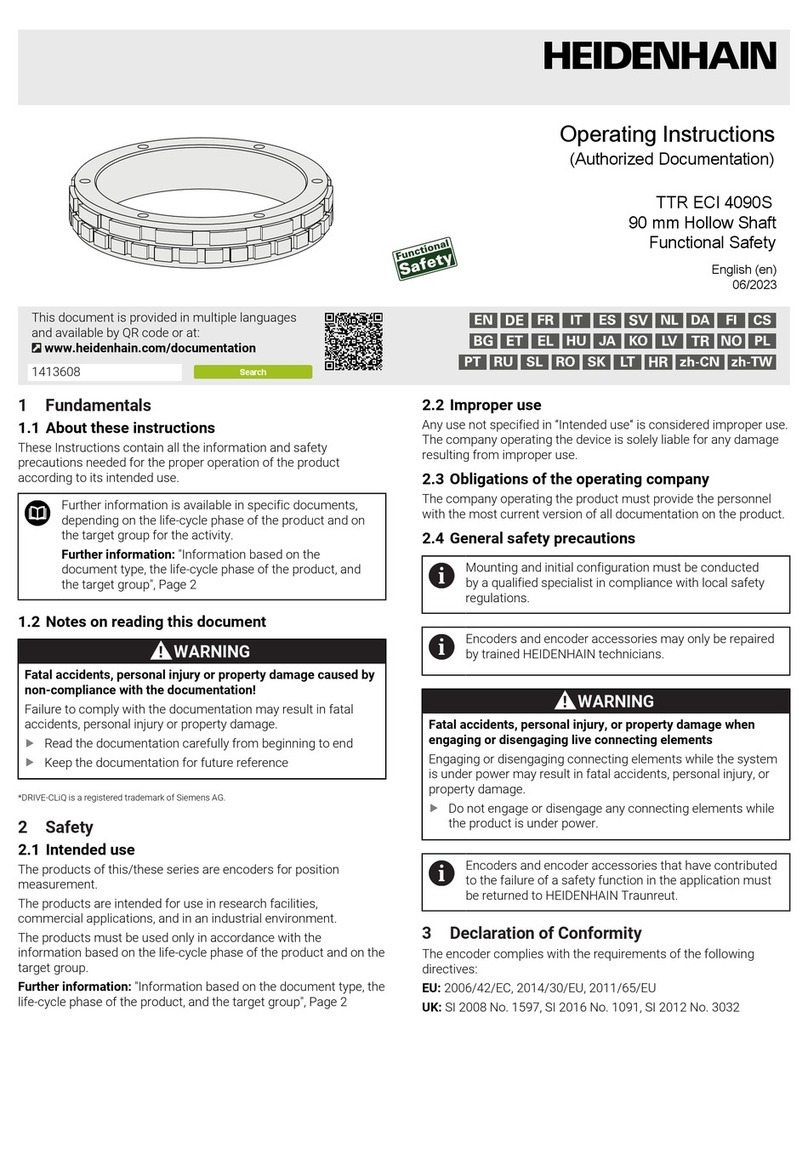
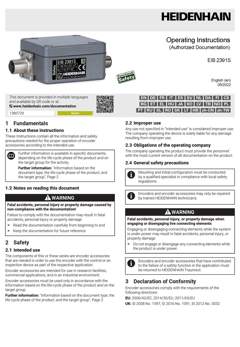
HEIDENHAIN AE ECI 4090S User manual

HEIDENHAIN

HEIDENHAIN AE ECI 4090S User manual

HEIDENHAIN TTR ECI 4090S User manual

HEIDENHAIN

HEIDENHAIN TTR ECI 4090S User manual

HEIDENHAIN LIP 2x1 User manual

HEIDENHAIN

HEIDENHAIN LIP 2x1 User manual

HEIDENHAIN ND 2100 G GAGE-CHEK User manual

HEIDENHAIN

HEIDENHAIN ND 2100 G GAGE-CHEK User manual

HEIDENHAIN ERP 880 User manual

HEIDENHAIN

HEIDENHAIN ERP 880 User manual

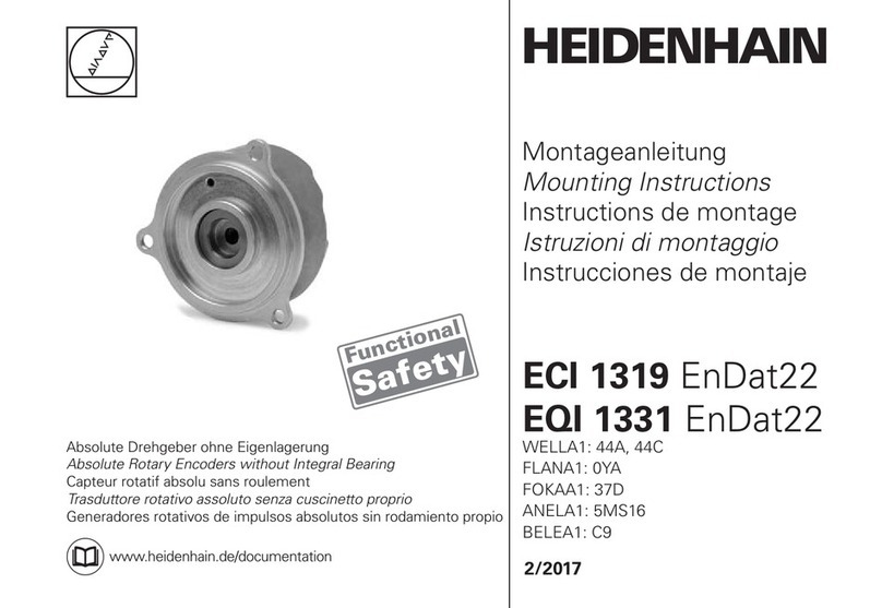
HEIDENHAIN ECI 1319 EnDat22 User manual

HEIDENHAIN

HEIDENHAIN ECI 1319 EnDat22 User manual

HEIDENHAIN QAN 200L User manual

HEIDENHAIN

HEIDENHAIN QAN 200L User manual

HEIDENHAIN ERN 420 TTL User manual

HEIDENHAIN

HEIDENHAIN ERN 420 TTL User manual

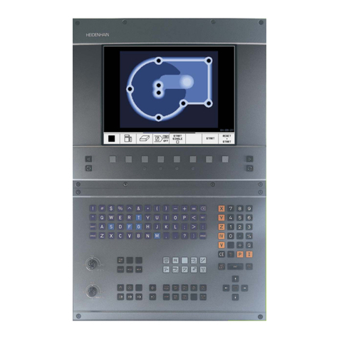
HEIDENHAIN TNC 426 CB User manual

HEIDENHAIN

HEIDENHAIN TNC 426 CB User manual

HEIDENHAIN LC 2x1 User manual

HEIDENHAIN

HEIDENHAIN LC 2x1 User manual

HEIDENHAIN EQI 1131 E30-R2 User manual

HEIDENHAIN

HEIDENHAIN EQI 1131 E30-R2 User manual

HEIDENHAIN ND 2100G User manual

HEIDENHAIN

HEIDENHAIN ND 2100G User manual

HEIDENHAIN ECN 413 User manual

HEIDENHAIN

HEIDENHAIN ECN 413 User manual

HEIDENHAIN LS 3x8 User manual

HEIDENHAIN

HEIDENHAIN LS 3x8 User manual

HEIDENHAIN PP 271A User manual

HEIDENHAIN

HEIDENHAIN PP 271A User manual

HEIDENHAIN MSE 1180 User manual

HEIDENHAIN

HEIDENHAIN MSE 1180 User manual

HEIDENHAIN ND 1400 QUADRA-CHEK -  GUIDE User manual

HEIDENHAIN

HEIDENHAIN ND 1400 QUADRA-CHEK - GUIDE User manual

HEIDENHAIN ECI 1119 EnDat22 User manual

HEIDENHAIN

HEIDENHAIN ECI 1119 EnDat22 User manual

HEIDENHAIN LIDA 279 User manual

HEIDENHAIN

HEIDENHAIN LIDA 279 User manual

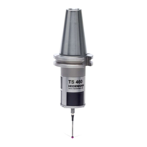
HEIDENHAIN TS 460 User manual

HEIDENHAIN

HEIDENHAIN TS 460 User manual

HEIDENHAIN TNC 426 User manual

HEIDENHAIN

HEIDENHAIN TNC 426 User manual

HEIDENHAIN ERN 1323 User manual

HEIDENHAIN

HEIDENHAIN ERN 1323 User manual

HEIDENHAIN MSE 1300 User manual

HEIDENHAIN

HEIDENHAIN MSE 1300 User manual

Popular Industrial Equipment manuals by other brands

U-Line H-9045 manual

U-Line

U-Line H-9045 manual

HOMEDEPOT 131-4168 installation instructions

HOMEDEPOT

HOMEDEPOT 131-4168 installation instructions

Oriental motor World K Series operating manual

Oriental motor

Oriental motor World K Series operating manual

woodmizer Accuset 2 Safety, Operation, Maintenance & Parts Manual

woodmizer

woodmizer Accuset 2 Safety, Operation, Maintenance & Parts Manual

Ebmpapst R1G133-AA17-02 operating instructions

Ebmpapst

Ebmpapst R1G133-AA17-02 operating instructions

Oriental motor EAC Series operating manual

Oriental motor

Oriental motor EAC Series operating manual

Meanwell UHP-200A Series manual

Meanwell

Meanwell UHP-200A Series manual

Pro-Cut B17 quick start guide

Pro-Cut

Pro-Cut B17 quick start guide

Tolomatic LS10 Disassembly and Assembly Instructions

Tolomatic

Tolomatic LS10 Disassembly and Assembly Instructions

Con-form SCREENS TO CONCRETE Assembly & instruction manual

Con-form

Con-form SCREENS TO CONCRETE Assembly & instruction manual

Goldmedal 2149 instruction manual

Goldmedal

Goldmedal 2149 instruction manual

Flex-A-Seal 58 Installation, operation, maintenance guide

Flex-A-Seal

Flex-A-Seal 58 Installation, operation, maintenance guide

System air SAVE-P VTR 150/B installation instructions

System air

System air SAVE-P VTR 150/B installation instructions

Flex-A-Seal 23M Installation, operation, maintenance guide

Flex-A-Seal

Flex-A-Seal 23M Installation, operation, maintenance guide

Power-Tronics SE3000B-3P manual

Power-Tronics

Power-Tronics SE3000B-3P manual

KEBCO COMBIVERT G6 Instructions for use

KEBCO

KEBCO COMBIVERT G6 Instructions for use

Haufftechnik HRD Series Assembly instruction

Haufftechnik

Haufftechnik HRD Series Assembly instruction

Hoffmann&Hoffmann Dripmaster EDD-4C user guide

Hoffmann&Hoffmann

Hoffmann&Hoffmann Dripmaster EDD-4C user guide

manuals.online logo
manuals.online logoBrands
  • About & Mission
  • Contact us
  • Privacy Policy
  • Terms and Conditions

Copyright 2025 Manuals.Online. All Rights Reserved.