WPI UltraPath 2 Parts list manual

SYSTEM GUIDE
for visible and ultraviolet (UPUV-2) systems
UltraPath 2
Multiple pathlength sample cell for absorbance
spectroscopy with extended dynamic range
Serial No._____________________
www.wpi-europe.com
180522

Page | 2
CONTENTS
GENERAL WARNINGS AND CAUTIONS......................................................................................... 3
INTRODUCTION ........................................................................................................................... 4
INSTRUMENT DESCRIPTION ........................................................................................................ 5
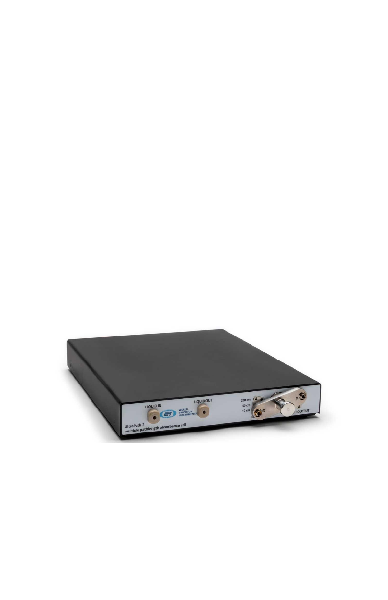
UltraPath 2 Sample Cell..................................................................................................... 6
TIDAS S 300 UV/VIS Spectrometer .................................................................................... 7
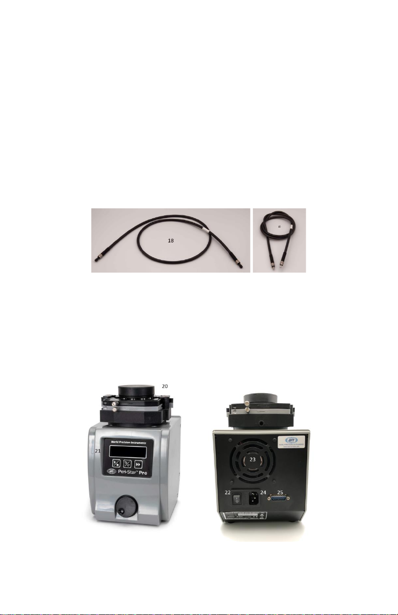
Fiber Optic Cables ............................................................................................................. 8
Peri-Star Pro Peristalitic Pump .......................................................................................... 8
Cleaning Kit (Available US Only)........................................................................................ 9
LWCC Injection System...................................................................................................... 9
Setting up UltraPath 2 ............................................................................................................... 10
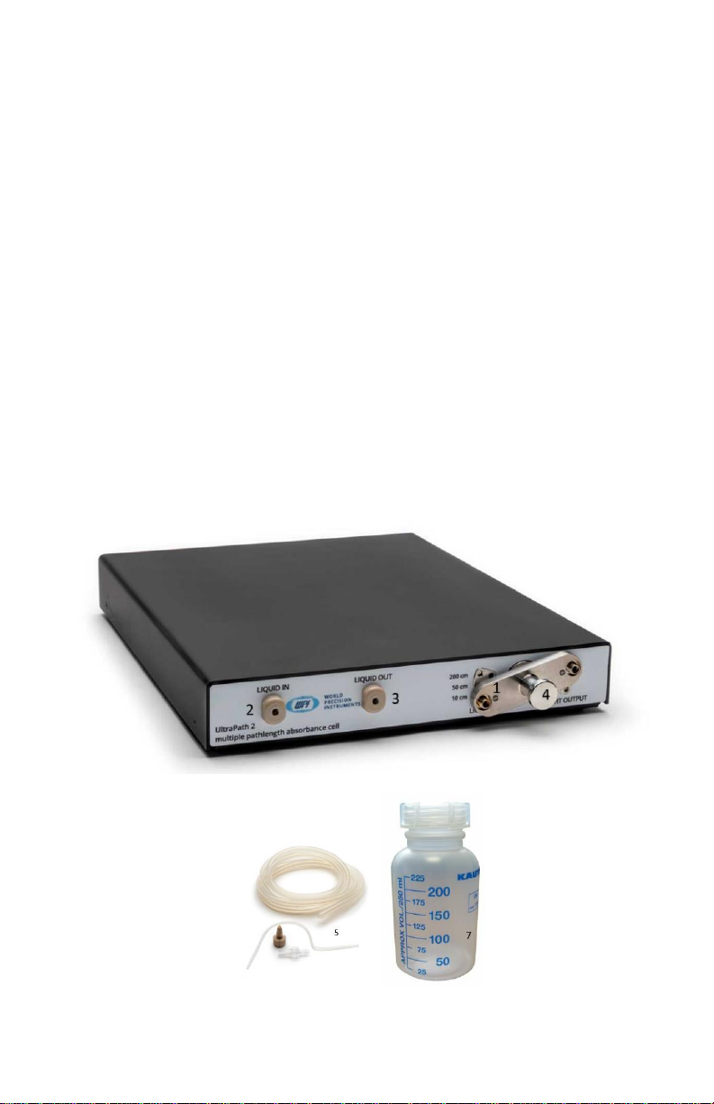
Parts List.......................................................................................................................... 10
Opening the package ...................................................................................................... 10
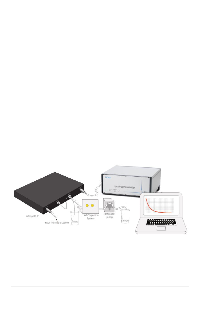
Assembling the UltraPath 2 system ................................................................................ 12
Installing the software .................................................................................................... 13
Setting up QFT2 Glass Fiber Filter (GF/F) & cuvette holder....................................................... 14
Using UltraPath 2....................................................................................................................... 15
How to fill the UltraPath 2 sample cell............................................................................ 15
Acquiring Data with TIDASDAQ –a typical measurement cycle...................................... 16
Refractive index sensitivity of the UltraPath 2 sample cell ............................................. 18
- salinity matched reference solutions to avoid baseline offsets .................................... 18
Measurement reliability.................................................................................................. 18
Flow rate and maximum pressure................................................................................... 18
Effective pathlength and linearity................................................................................... 19
Using the QFT2 cuvette holder for particulate absorption measurements............................... 20
Background ..................................................................................................................... 20
Taking particulate absorption measurements with a GF/F pad ...................................... 21
Taking cuvette measurements........................................................................................ 21
Relevant Literature for particulate absorption measurements ...................................... 22
Instrument Maintenance........................................................................................................... 23
Self-Test..................................................................................................................................... 25
Troubleshooting ........................................................................................................................ 26
Storage ...................................................................................................................................... 28
Accessories ................................................................................................................................ 29
Specifications............................................................................................................................. 30
References................................................................................................................................. 31
WARRANTY................................................................................................................................ 33
Copyright © 2022 by World Precision Instruments. All rights reserved. No part of this publication may be
reproduced or translated into any language, in any form, without prior written permission of World
Precision Instruments.

3 | P a g e
GENERAL WARNINGS AND CAUTIONS
Read this manual before you attempt to use this instrument.
All warnings on the unit and in these operating instructions should be adhered to.
Warning: Do not look directly into the light output of the light source. light radiation may
damage your eyes.
Warning: Do not remove any safety devices installed. this will void your warranty and create
an unsafe operating condition.
Warning: Dangerous voltages are present. No user serviceable parts inside unit. Instrument
should be serviced by qualified service personnel only.
Warning: The UltraPath 2 sampling system contains cleaning solutions. only qualified
personnel should use these solutions. Please refer to the SDS Sheets for details on the
solutions.
Warning: Before using the instrument for the first time, check for transport damage.

Page | 4
INTRODUCTION
The UltraPath 2 sampling system is a unique high-performance spectrophotometer offering
user-selectable optical path lengths of 10, 50 and 200 cm. Designed for the detection of low
absorbing species in solution, UltraPath 2 is an ideal tool for any study requiring precise and
highly sensitive spectroscopic determination of analytes, either in the lab or in the field. The
instrument operates in the wavelength range of 220 to 720 nm (UPUV-2) and has an
exceptional dynamic range allowing reliable absorbance measurements between 5μAU/cm to
1 AU/cm to be routinely made.
The UltraPath system was developed by WPI under a collaborative agreement with NASA
(Stennis Space Center) for the spectroscopic determination of colored dissolved organic matter
(CDOM) in seawater and freshwater environments. It was designed for use in the laboratory
and in the field (i.e., at sea). CDOM concentrations vary significantly between open ocean
samples with low CDOM (e.g., 0.007 m-1 at 380 nm), and high CDOM freshwater environments
(e.g., 10-20 m-1 at 380 nm).
To address these problems the design requirements of UltraPath mandated the development
of a rugged portable system capable of highly sensitive measurements across a wide dynamic
range.
The UltraPath 2 sample cell has three optical pathlengths contained within a single sample cell
(10 cm, 50 cm and 200 cm). The pathlengths are user selectable, offering a very high sensitivity
and an extended dynamic range for VIS and UV absorbance measurements. The fluid path of
the sample cell is optimized to produce a laminar flow that is virtually free of interference from
trapped air bubbles and adherence of dissolved substances to the cell wall. In particular, the
design greatly minimizes the problems commonly found with flow cells of long optical
pathlengths: the risk of trapping dust particles, fibers or particulate matter inside the cell.

5 | P a g e
INSTRUMENT DESCRIPTION
The UltraPath 2 system includes a photodiode array-based spectrometer module (TIDAS S 300
UV/VIS) to measure the absorbance at the selected pathlength. Absorption of light is
measured between 190 to 720 nm with a resolution of 4 nm (FWHM) and a noise level below
0.2 mAU. The spectrometer includes an integrated deuterium/halogen light source which
delivers light via the supplied fiber optic cables to the UltraPath 2 sample cell. A peristaltic
pump (Peri-Star Pro) is utilized to evenly draw sample up into the Sample Injector and through
the UltraPath 2 sample cell.
The spectrophotometer is connected to the network via an ethernet port. The
TIDASDAQ/SpectraView software (included) is installed on a standard Windows PC or laptop
(not included) and connects to the TIDAS via the network. The TIDASDAQ/SpectraView
software displays and performs data collection and processing. High precision absorbance or
transmittance spectra can be obtained within seconds. Key features of the software package
include ease-of-use, simple spectra acquisition, as well as tools for sample qualification,
quantification, and data extraction. (Refer to the TIDASDAQ & SpectraView manuals on the
USB drive for a detailed description of the software supplied with the instrument.)

Page | 6
UltraPath 2 Sample Cell
1. Fiber optic input connector
2. Liquid Input connector
3. Liquid Output Connector. Sample is removed from the UltraPath 2 sample cell via
the Liquid Output Connector with vacuum suction of the Peri-Star Pro peristaltic
pump.
4. Fiber Optic Switch & Output Connector. The optical pathlength of the UltraPath 2
can be switched between 10, 50 and 200 cm. Pull the knob and turn to the selected
pathlength
5. UltraPath 2 Sample Injector Kit. The Sample Injector (WPI #58006) is connected to
the Liquid Input connector (7). Sample is drawn into the UltraPath 2 sample cell with
the Sample Injector using vacuum suction of the Peri-Star Pro peristaltic pump.
6. Silicone pump tubing (WPI# 500320 –part of the sample injector assembly kit WPI#
58006).
7. Waste Bottle for expelled sample (included with WPI# 89372-2 LWCC Injection Kit).

7 | P a g e
TIDAS S 300 UV/VIS Spectrometer
8. Status LED. LED’s indicating the TIDAS S 300 UV/VIS state.
9. Error LED Indicator (Red). The Error LED lights up when the TIDAS S 300 UV/VIS is in
a fault state. On system start-up the error LED is on for up to 3 seconds.
10. Front Power Switch (ON/OFF). When the power switch is turned ON, power is
supplied to the TIDAS S 300 UV/VIS spectrometer module and this LED will be lit.
11. Fiber optic input (SMA type). The Fiber optic input connects to the light output of
the UltraPath 2 sample cell (4).
12. Debug RS-232. Interface for system diagnostics (connectors supplied). For further
instructions refer to TIDAS S 300 UV/VIS instruction manual.
13. LAN RJ45 ethernet communication interface. The TIDAS S 300 UV/VIS is connected
to a network via the supplied ethernet cable. For further instructions refer to TIDAS S
300 UV/VIS instruction manual.
14. Shutter Button: Pushing the shutter butting the shutter is toggled. If the shutter is
open the LED is lit.
15. Cooling Fan. The fan dissipated the heat generated by the power supply and
electronics of the TIDAS S 300 UV/VIS. To ensure proper ventilation, the unit should
be situated away from walls or panels. Do not obstruct the cooling fan openings.
16. Input terminal for power cord and fuse. The TIDAS S 300 UV/VIS accepts voltages
from 80 to 240 VAC, 50-60Hz. Use correct cord and fuse, as described in the manual.

Page | 8
17. Light output. SMA Fiber Optic Connector (collimator) with adjacent mounting
screws.
Fiber Optic Cables
18. Fiber optic cable —Light is coupled into the fiber optic input connector (1) of the
UltraPath 2 sample cell from the TIDAS S 300 UV/VIS light output (22) with a 600 μm
core fiber (WVLUXDUV-S-0600-SMA).
19. Fiber optic cable —Light is coupled from the output of the UltraPath 2 fiber optic
switch (4) into the TIDAS S 300 UV/VIS spectrometer Input (11) with a 600 μm core
fused silica fiber (WVLUXDUV-S-0600-SMA).
Peri-Star Pro Peristalitic Pump
20. Peri-Star Pro Pump Head. Two channels and eight rollers.
21. Control Panel. The Control Panel allows to start the pump clockwise and
counterclockwise, to increase and decrease pump speed between 0.1 rpm and 100
rpm, to stop the pump and to prime the pump (Refer to the Peri-Star Pro manual for
details).
22. Power Switch (ON/OFF). When the power switch is turned ON, power is supplied to
the Peri-Star Pro peristaltic pump

9 | P a g e
23. Cooling Fan. The fan dissipated the heat generated by the power supply, motor and
electronics of the Peri-Star pump. To ensure proper ventilation, the unit should be
situated away from walls or panels. Do not obstruct the cooling fan openings.
24. Input terminal for power cord.
25. External Control socket. DB-15 connection to control speed and direction of the
pump head. Refer to the instruction manual for details.
Cleaning Kit (Available US Only)
26. Waveguide Cleaning Kit. The waveguide cleaning kit contains three solutions
specifically developed to keep the UltraPath 2 sample cell clean and ensure a high
measurement accuracy and repeatability.
LWCC Injection System
27. 6 Port Injection Valve
28. 6 Port Selection Valve
29. LWCC Injection System Connection Kit to connect between the switch and samples,
reference solutions and cleaning solutions on the LWCC injection system.
For a detailed description of the TIDAS S 300 UV/VIS and Peri-Star Pro, refer to the relevant
manuals.

Page | 10
Setting up UltraPath 2
UltraPath 2 is a modular spectrophotometer system. Its main components are: UltraPath 2
sample cell and TIDAS S 300 UV/VIS spectrometer module. The assembly of the UltraPath 2
system is described below.
Parts List
Part Number
Quantity
Description
UPATH2-CELL
1
UltraPath 2 Cell
TIDAS S 300 UV/VIS
1
UV/VIS Spectrometer system (190-
720nm) including software, DH
Lightsource.
WVLUXDUV-S-0600-100-SMA
2
DUV Fiber (200-1200nm) 600um 100cm
SMA
WVLUXDUV-S-0200-100-SMA
1
DUV Fiber (200-1200nm) 200um 100cm
SMA
13395
2
SMA Bulkhead Feed Thru Connector, D-
hole
58006
1
Sample Injector Assembly for LWCC
58450
1
Kit, Adapter Syringe, LWCC
89372-2
1
LWCC Injection System
LOOP-5ML
1
Sample Loop Kit, 5 mL (2.5m PFA Tubing
1/16” ID x 1/8” OD + 2 x PEEK fittings 1/8"
OD Tubing x ¼”-28 UNF)
PERIPRO-4LS
1
Peristaltic Pump, 4 Channel, low speed
QFT2*
1
25mm GFF Filter and 10mm Cuvette
Holder, SMA
CUV2012-1*
1
Quartz Cuvette, Style C, 12.4x12.4x45mm,
10mm, 3.5ml
* Used when you need to measure particulate absorption on glass fiber filter pads (see
Setting up QFT2 Glass Fiber Filter section) –not used with the UltraPath 2 System setup.
Opening the package
Upon receipt of this system, make a thorough inspection of the contents and check for
possible damage. Concealed loss or damage should be reported at once to the carrier and an

11 | P a g e
inspection requested. Please read the section entitled “Claims and Returns” on the warranty
page of this manual. Please call WPI Technical Support if any parts are missing.

Page | 12
Assembling the UltraPath 2 system
1. Prepare a clear workspace for all components.
2. From left to right place the following components on the workspace: UltraPath 2
sample cell, LWCC injection system, Peri-Star Pro peristaltic pump and TIDAS S 300
UV/VIS spectrometer.
3. Use a 600 μm core diameter fiber optic cable (18) to connect the light output (17) of
the TIDAS S 300 UV/VIS spectrometer to the fiber optic input connector (1) of the
UltraPath 2 sample cell.
4. Use a 600 μm core diameter fiber optic cable (19) to connect the light output (4) of
the UltraPath 2 Fiber Optic Switch to the fiber optic input (11) of the TIDAS S 300
UV/VIS spectrometer.
5. Connect the TIDAS S 300 UV/VIS to the network via the RJ45 connector.
6. Connect the Power cord supplied with the to the TIDAS S 300 UV/VIS to the Input
Terminal (16) of the TIDAS S 300 UV/VIS and the mains.
7. Assemble the sample injector loop of the UltraPath 2 Sample Injector Kit (5) by
sliding on a nut and a ferrule and then screwing the assembly into the bulkhead
fitting labelled “liquid in” (2) of the UltraPath 2 sample cell. Note: there are two ways
the yellow ferrule will go onto the tubing; the wider side should face the end of the
assembly. Finger tighten only!
Place the injector into a sample vial filled with de‑ionized water.
8. Use the silicone pump tubing (6) to connect the liquid output port (3) of the
UltraPath 2 sample cell via the Peri-Star Pro peristaltic pump to the Waste bottle (11)
(See Peri-Star Pro instruction manual for details).
9. Turn on the Peri-Star Pro and the TIDAS S 300 UV/VIS —allow lamp to warm up at
least 15 minutes before sampling.
Note:

13 | P a g e
The 89372-2 LWCC Injections system together with the LOOP-5ML can be used in the setup to
provide an efficient, continual flow for injecting a sample through the UltraPath 2. It minimizes
contamination and the formation of tiny bubbles that interfere with spectroscopic data
recording. (See the LWCC Injection System Manual for connection details)
The QFT2 and CUV2012-1 are not part of the standard setup. They are used when you need to
measure particulate absorption on glass fiber filter pads (see section on Setting up QFT2 Glass
Fiber Filter (GF/F) & cuvette holder)
Installing the software
For hardware and software installation of the TIDAS S300, please refer to included TIDAS S
User Manual and the TIDAS DAQ3 User Manual.

Page | 14
Setting up QFT2 Glass Fiber Filter (GF/F) & cuvette holder
The components required to measure particulate absorption on glass fiber filter pads are:
TIDAS S 300 UV/VIS
1
UV/VIS Spectrometer system (190-720
nm) including software, DH Lightsource.
WVLUXUVIS-S-1000-100-
SMA
1
UVIS Fiber (260-1200 nm) 1000 µm
100 cm SMA
WVLUXUVIS-S-0600-100-
SMA
1
UVIS Fiber (200-1200nm) 600 µm 100 cm
SMA
QFT2
1
25 mm Glass Fiber Filter (GF/F) and 10mm
Cuvette Holder
CUV2012-1
1
Quartz Cuvette, Style C, 12.4x12.4x45
mm, 10 mm, 3.5 ml
The light output of the TIDAS spectrophotometer is connected to one optical port of the QFT2
using the UVIS Fiber with a core diameter of 1000 µm. The second port of the QFT2 is
connected to the detector input of the TIDAS spectrophotometer with the UVIS Fiber with a
core diameter of 600 µm.

15 | P a g e
Using UltraPath 2
UltraPath 2 is a very sensitive device for measuring low absorbing substances in solution.
The following instructions will familiarize you with using and cleaning the UltraPath 2 system.
•Switch the TIDAS S 300 UV/VIS ON (10) and start the TIDASDAQ software. Allow its
light source approximately 15 minutes warming up time for the lamp to stabilize its
temperature drift (<0.5mAU/h). For test purposes, the lamp may be used earlier.
Open the shutter (14) at the light source to take measurements. Close the shutter
when a dark current has to be taken.
•Switch the pump (Peri-Star Pro) ON (22) and with size #14 tubing set the pump speed
to 60 RPM or 12mL/min via the control panel (21). The sample is drawn into the
waveguide by vacuum suction.
•Select a pathlength (10, 50, 200 cm) at the fiber optic switch (4) of the UltraPath 2
sample cell.
How to fill the UltraPath 2 sample cell
•Place the injector (5) into a sample vial. The sample is drawn with the peristaltic
pump (Peri-Star Pro) into the UltraPath 2 sample cell by vacuum suction.
•Press the forward button at the control panel (21) of the Peri-Star Pro to start
drawing sample solution into the cell.
•Lift the sample injector between samples to allow for an air bubble to enter the
injector tubing. In this way samples can be separated and cross contamination due to
mixing minimized.
•Using the 10cm or 50cm cell, a pumping time of approx. 30 seconds is necessary,
using the 200cm path, a pumping time of approximately 60 seconds is necessary to
fill the cell completely with sample solution.
•The cell is completely filled when the air bubble generated earlier exits the “Liquid
out” connector (3) of the sample cell.

Page | 16
Acquiring Data with TIDASDAQ –a typical measurement cycle
After the light source is running for 15 minutes, the waveguide is filled with reference solution
and the TIDASDAQ software started. Measurements can then be taken by the following steps.
1. Define Directory, Filename and Comment of your dataset.
2. Press the Settings icon to open the TIDASDAQ Parameter window.
Use the following typical parameters to get started:
Scan range to 190-720 nm
Representation to Absorbance,
Scan Type to Time scan, Integration time to 240 ms
Accumulations to 4,
Sample Interval to 1 s

17 | P a g e
Total scan time to 3 min
(Adjust these settings later depending on your pathlength setting.)
Use the Monitor Parameter function icon to set integration time of the TIDAS S 300 UV/VIS. A
maximum of 45000 cts should be observed, when using MilliQ water in the UltraPath 2 sample
as a reference. Typical integration times are 100 to 2000ms.
Sample collection
1. Close the shutter at the light source (14) and take a Dark Scan
2. Open the shutter (14) at the light source and press the Reference Scan icon to take a
reference signal.
3. Press the Scan Start icon to start a continuous scan.
4. Start the pump and draw sample into the UltraPath 2 sample cell (See “How to fill the
UltraPath 2 sample cell” for details).
5. Introduce an air bubble of approximately the length of the Injector tubing at the liquid input
of the UltraPath 2 sample cell and draw the sample into the cell.
6. A very high absorbance signal will be observed until the sample cell is filled with the sample
solution, then a steady signal will be present. This may take between 15 seconds and 1 minute,
depending on the pathlength used.
It is good practice to measure the baseline with reference solution at the beginning and the
end of the measurement cycle. Thus, introduce a second air bubble and draw a second draw
reference solution into the sample cell until a stable baseline signal has been reached. After
the signal has returned to the baseline, stop the continuous measurement cycle by pressing
the Start Scan icon.
NOTE:
1. Sample Cell Preparation
It is good practice to fill the UltraPath 2 at the beginning of each measurement cycle with clean
deionized water and measure the Light intensity throughput of the cell for quality reference.
This allows the user to determine if the sample cell is contaminated and needs cleaning.
2. Seawater
WPI highly recommends using salinity matched reference solutions, when working with
seawater to avoid absorbance baseline offsets caused by refractive index variations when
reference and sample solution have different salinities.

Page | 18
Refractive index sensitivity of the UltraPath 2 sample cell
- salinity matched reference solutions to avoid baseline offsets
The UltraPath 2 sample cell is sensitive to variations in refractive index between reference and
sample solution. When measuring in saline solutions, such as e.g. colored dissolved organic
matter (CDOM ) in seawater, it is recommended to use a reference/standard solution of
matched salinity. These reference solutions should be filtered with the same filter material as
the sample (e.g., 0.2-micron filters).
Saline solutions have a slightly higher refractive index that pure water, resulting in a negative
absorbance baseline shift compared to de-ionized water. For more information see:
Richard L. Miller, Mathias Belz, Carlos Del Castillo, Rick Trzaska,
“Determining CDOM Absorption Spectra in Diverse Coastal Environments
Using a Multiple Pathlength, Liquid Core Waveguide System”, Continental
Shelf Research (July 2002), 22:9, p 1301-1310.
Measurement reliability
Baseline absorbance measurements should be within ± 1-2 mAU between baseline
samples. If larger baseline variations are observed, the following problems may be
present:
1. An air bubble is trapped inside the cell. Allow for more sample to be injected and
scan again.
2. The cell is contaminated. Follow the cleaning protocol and take a new reference.
3. The salinity of the sample is not the same as the salinity of the reference solution. If
working in saline environments, prepare saline-matched reference solutions to
accommodate for baseline shifts.
See instrument maintenance and troubleshooting section on how to overcome these
problems.
Flow rate and maximum pressure
The applied pressure and fluid flow rate through the LWCC /UltraPath 2 obeys the Hagen-
Poiseuille relationship. Flow is proportional to pressure and to the fourth power of the
diameter of the sample cell, as well as reciprocal to the length of the cell and fluid viscosity.
Typical flow rates of the UltraPath 2 sample cell are 12 mL/ min (equal to 60 RPM with the
Peri-Star Pro pump using size #14 tubing). Drawing liquid into the cell via the injector fills the
sample cell. The UltraPath 2 sample cell is designed for low pressure operations and should not
be used at pressures greater than 75 PSI.

19 | P a g e
Effective pathlength and linearity
Effective pathlength and linearity have been extensively studied with WPI’s Liquid waveguide
capillary cell technology and the UltraPath 2 system. “Effective pathlength” is defined as the
equivalent pathlength of the cell if we assume the LWCC strictly follows Beer’s law:
𝐴 = 𝜀 ∗ 𝐶 ∗ 𝜆
where A is absorbance, 𝜀is the absorption coefficient, 𝐶is concentration and 𝜆is the optical
pathlength of the sample cell. UltraPath 2’s three pathlengths (10, 50 and 200 cm) are
manufactured with a tolerance of ± 2 mm and calibrated experimentally with a dye solution
(Amaranth).
The pathlength marked on the QS-Sheet supplied with UPATH-2 flowcell is its calibrated
effective pathlength.
By Beer’s Law, the absorption of a liquid sample in a long pathlength sample cell bears a linear
relationship to the concentration of an analyte. WPI’s sample cells based on Liquid Waveguide
Technology were extensively tested and proved to be linear over a range 0.01 to 2.0 AU
(limited only by noise and stray light from the measuring spectrophotometer).
Relevant Literature
A detailed analysis of the effective pathlength and linearity of WPI’s UltraPath 2 sample cell
and WPI’s waveguide technology has been published in the following papers:
Richard L. Miller, Mathias Belz, Carlos Del Castillo, Rick Trzaska,
“Determining CDOM Absorption Spectra in Diverse Coastal Environments
Using a Multiple Pathlength, Liquid Core Waveguide System”, Continental
Shelf Research, July 2002, 22:9, p 1301-1310.
Mathias Belz, Peter Dress, Aleksandr Sukhitskiy and Suyi Liu, “Linearity
and effective optical pathlength of liquid waveguide capillary cells”, SPIE
Conference on Internal Standardization and Calibration Architectures for
Chemical Sensors, Boston, September 1999, SPIE Vol. 3856, 271-281.

Page | 20
Using the QFT2 cuvette holder for particulate absorption
measurements
Background
The rugged and portable QFT2 is specially designed for measuring absorption of particulate
concentrated on Glass Fiber Filter (GF/F) Pads and for simple cuvette measurements in 10 mm
cuvettes. Instead of collecting samples and transporting them to a laboratory, samples can be
measured on-site.
Particulate absorption of fresh water and seawater can be determined by filtering a known
amount of sample through a Glass Fiber Filter (GF/F) and measuring the particulate absorption
coefficient ap(λ) concentrated on the filter. This technique is called quantitative filter technique
(QFT) and corrects for the pathlength amplification, an effect of scattering. The correction of
the pathlength amplification and the correction of the non-linear relationship between the
optical density of samples on a Whatman GF/F filter and in suspension are discussed in
Mitchell (1990). (See "References" on page 9). Mitchell’s report results in an equation to
calculate the corrected particulate absorption coefficient ap(λ) as follows:
with
Table of contents
Other WPI Laboratory Equipment manuals
Popular Laboratory Equipment manuals by other brands

Kaye
Kaye ValProbe RT user manual

Bibby Sterilin
Bibby Sterilin stuart HM50C Instructions for use

Nippon Genetics Europe
Nippon Genetics Europe FastGene manual

Thermoline Scientific
Thermoline Scientific TO Series User manual & setup guide

Lafayette Instrument
Lafayette Instrument 76604US user manual

Endress+Hauser
Endress+Hauser analytikjena qTOWER3 84 auto operating manual