578
6
Accuracy (Accuracy guaranteed for one year at 23°C±5°C (73°F±9°F),
80%RH or less.) Battery low display is off.
*1:Overload protection is 600 V DC/AC rms (sine wave) or 3x10⁶VHz
(for 1 min.), for all functions and ranges.
dgt.: resolution (The smallest displayable unit, i.e., the input value that causes
the digital display to show a "1".)
rdg.: reading value (The value currently being measured and indicated on the
measuring product)
Auto/Manual Range Function ( V, only)
Autoranging: The Autoranging function automatically selects the opti-
mum measurement range.
Turning on the power also switches Autoranging on (AUTO lights up).
The range automatically switches up when the display shows 4200
counts or more, and down when the display shows less than 400
counts. (A beep sound is generated when the 3246-60 is switched to a
different range.)
Manual ranging: Set a range manually.
Turn on the power while pressing the select button (
AUTO
is turned off).
Range selection: Each pressing of the select button selects the next
larger range. After the largest range, pressing the select button again
returns you to the smallest range.
Press and hold down the select button (for about 1 second) to select
AC or DC in manual ranging mode, or select between resistance mea-
surement, continuity check, and diode check in manual ranging mode.
The Manual ranging function is active until the 3246-60 is turned off.
Hold Function [ ] (Available for any measurement function.)
Press HOLD to hold the measurement value ( lights up).
In hold mode, the select button operation, the warning beep for voltage
measurement overflow, and beep for diode check judgment are disabled.
To cancel the hold mode: Press HOLD again.
Auto Power Save Function [APS] (Available for any measurement
function.)
When the measurement product is turned on, it automatically enters
Auto Power Save mode (APS lights up).
Approximately 10 minutes after completing final operation, the mea-
surement product automatically enters Power Save mode with a beep-
ing sound.
Exiting the Power Save State: turn off the power once.
Disabling Auto Power Saving: turn on the power while pressing
HOLD. (APS is turned off)
Overflow Warning Function [OF] (Vonly)
When the measured value exceeds the maximum indication, a beep
sound is generated (OF lights up).
This function is disabled in hold mode.
Penlight/LCD Backlight Function
• ON: Press and hold down HOLD. The penlight and LCD backlight
will light. (The hold mode is not influenced)
• OFF: The lights will go off automatically in about 10 seconds. Oper-
ating the Function Selector or a key will turn off the lights in about10
seconds after the last key operation.
• Hold down HOLD to keep the lights on.
Pre-Operation inspection
To avoid the possibility of electric shock or incorrect measure-
ment, check the following items before using the product.
If the operation check reveals any abnormalities, stop the
check immediately and do not use the product.
• For voltage measurement, short the test leads and check that
0 V is displayed.
• For Measuring Resistance or Continuity Check, short the test
leads and check that 0 is displayed.
• Measure a test item with a known value (battery, AC supply,
resistor, etc.) to confirm that the known value can be displayed.
Display Elements
3(1/2) dgt., Max. 4199 counts (600 VAC/DC range: 699 counts)
Polarity indicator: “–” sign (automatic)
Overflow indicator: “OF” or “–OF”
Units and Symbols (AC), (DC), , AUTO, HOLD, , , APS, M,
k, m, V,
Range Switching Auto/Manual range
Sampling Rate 2.5 S/s
Input Terminals V/ / continuity/ diode terminal, COM terminal
Functions OFF/ V/
Buttons HOLD, (select)
Power Supply Coin-shaped lithium battery CR2032 × 1
Battery-Life Warning indicates low battery
Dimensions Approx. 30W ×182H ×26.5D mm (without protrusions)
(1.18”W × 7.17”H × 1.04”D)
Cable length:Approx. 800 mm (31.50”)
Mass Approx.80 g (2.8 oz.)(including battery)
Operating
Environment Indoors,Pollution Degree 2, altitude up to 2000 m (6562-ft.)
Operating Tempera-
ture & Humidity 0 to 40°C (32 to 104°F), at 80%RH or less
(non-condensating)
Storage Tempera-
ture & Humidity -20 to 60°C (-4 to 140°F), at 70%RH or less
(non-condensating)
Accessories Instruction Manual
Coin-shaped lithium battery (CR2032) x1 (supplied with this
product for monitor), Sleeves (red and black 1 piece for each)
Standards
Applying Safety EN61010
EMC EN61326
Electrical Characteristics
Accuracy guarantee
for temperature and
humidity 23°C±5°C (73°F±9°F), 80%RH or less
(non-condensating)
Regulated
power supply range 2.15 V to 3.4 V (Battery low display is off)
Temperature
Characteristic (Measurement accuracy) × 0.1/°C (except 23°C±5°C)
Noise Suppression
NMRR DCV: 40dB or better (50/60 Hz)
ACV: 40dB or better (DC)
CMRR DCV:100dB or better (50/60 Hz)
ACV: 60dB or better (50/60 Hz)
(1kUnbalance)
Dielectric Strength Input terminals to case: 5.55 kVrms sin (50/60 Hz for one
minute)
Maximum input
Voltage 600 VDC/ 600 Vrms (sin) or 3 ×10⁶ VHz
Maximum rated
voltage to earth When sleeve is installed : CAT IV (300 V) / CAT III (600 V)
When sleeve is uninstalled: CAT II (600 V),
(Anticipated Transient Overvoltage: 6000 V)
Rated Power
Supply Voltage 3.0 VDC
Maximum
Rated Power 30 mVA (Max) (supply voltage 3.0 VDC)
Rated Power 4 mVA (Typ) (supply voltage 3.0 VDC, in DCV mode)
Power during Auto
Power Saving 0.1 mVA (Max)
Continuous
Operating Time Approx. 150 hours (in DCV mode)
Approx. 30 hours (with light in repeating cycles of 10 sec-
onds on and 20 seconds off, in DCV mode)
Range Accuracy
Input Impedance
Notes*1
DC Volt-
age Mea-
surement
(DCV)
420.0 mV
4.200 V
42.00 V
420.0 V
600 V
±1.3%rdg.±4dgt.
100 M
or more
Approx. 11 M
Approx. 10 M
Approx. 10 M
Approx. 10 M
AC Voltage
Measure-
ment
(ACV)
4.200 V
42.00 V
420.0 V
600 V ±2.3%rdg.±8dgt. Approx. 11 M
Approx. 10 M
Approx. 10 M
Approx. 10 M
Measurement fre-
quency range:
50 Hz to 500 Hz
Range Accuracy Open terminal
voltage Notes*1
Resistance
Measure-
ment ()
420.0
4.200 k
42.00 k
420.0 k
4.200 M
42.00 M
±2.0%rdg.±4dgt.
±2.0%rdg.±4dgt.
±2.0%rdg.±4dgt.
±2.0%rdg.±4dgt.
±5.0%rdg.±4dgt.
±10.0%rdg.±4dgt.
3.4 V or less
Approx. 0.7 V
Approx. 0.5 V
Approx. 0.5 V
Approx. 0.5 V
Approx. 0.5 V
Measurement cur-
rent: 800 A max.
Varies according to
resistance levels to
be measured.
Continuity
Check( ) 420.0 ±2.0%rdg.±4dgt. 3.4 V or less Threshold level
(beep sound):
50 ±40
Diode
Check( ) Judgment only
(0.3 V to 2.0 V) 3.4 V or less Measurement cur-
rent: 800 A max.
Functions
Measurement Procedures
Observe the following precautions to avoid electric shock.
• Do not grip the 3246-60 or test lead between the barrier
and the tip during operation (
See "Parts Names"
).
• Disconnect the test leads from the measurement object
before handling the Cap.
• Always verify the appropriate setting of the Function
Selector before connecting the test leads.
• Disconnect the test leads from the measurement object
before switching the Function Selector.
• Never apply voltage to test leads when the Resistance,
Continuity or Diode Check functions are selected.
Doing so may damage the product and result in per-
sonal injury. To avoid electrical accidents, remove
power from the circuit before measuring.
Range Accuracy
Input Impedance
Notes*1
To prevent an electric shock accident, confirm that the white
portion (insulation layer) inside the cable is not exposed. If a
color inside the cable is exposed, do not use the cable. Using
the instrument in such conditions could cause an electric
shock, so contact your dealer or Hioki representative for repair.
Periodic calibration and inspection is necessary in order to
ensure that this product operates according to its product spec-
ifications.
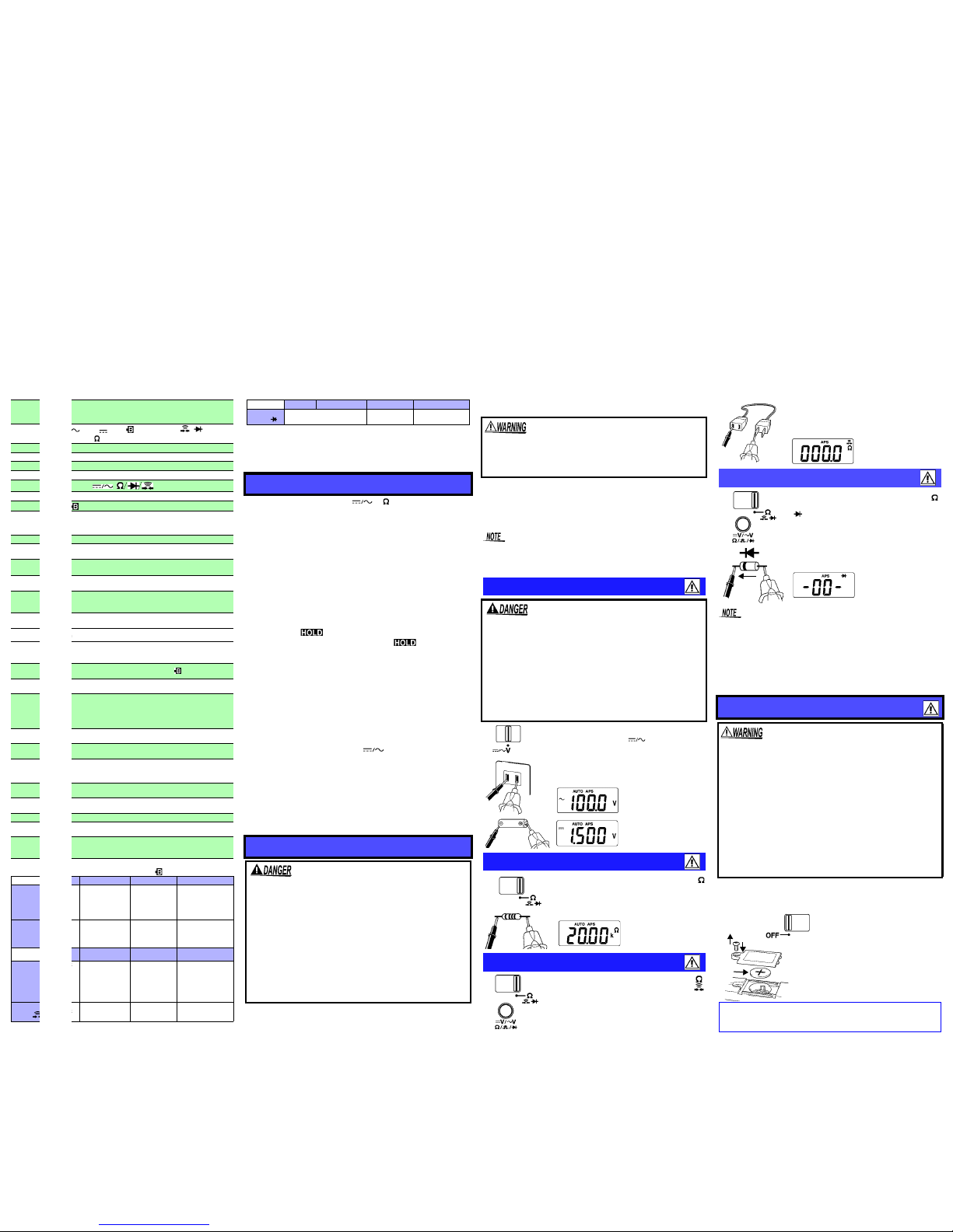
Voltage Measurement
• The maximum input voltage is 600 V DC/ 600 Vrms (sin)
or 3x10⁶V•Hz. Attempting to measure voltage in excess
of the maximum rating could destroy the product and
result in personal injury or death.
• To avoid electrical shock, be careful to avoid shorting
live lines with the test leads.
• For safety, test lead connections must always be made
at the secondary side of a circuit breaker.
• The maximum rated voltage between input terminals
and ground is 600 V DC/AC. Attempting to measure
voltages exceeding 600 V with respect to ground could
damage the product and result in personal injury.
Resistance Measurement
Continuity Check