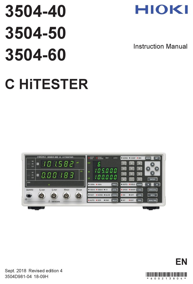
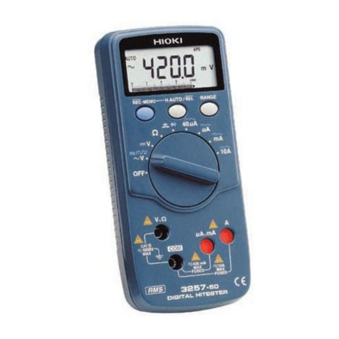
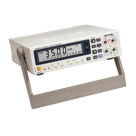
Hioki 3290-10 User manual


i
Contents
1
2
3
4
5
6
7
8
9
10
11
APPX
IDX
Contents
Introduction .................................................................. 1
Checking the Contents of the Package ........................ 1
Safety Notes ................................................................ 2
Usage Notes ................................................................ 5
1Overview 9
1.1 Product Overview ............................................... 9
1.2 Features ...........................................................10
1.3 Identification of Controls and Indicators ...........12
1.3.1 Model 3290-10 CLAMP ON AC/DC HiTESTER 12
1.3.2 Model 9691, 9692, 9693 CLAMP ON AC/DC
SENSOR (Optional)............................................18
1.4 Buttons Operations ...........................................19
1.5 Measurement Modes ........................................20
1.6 Quick References .............................................21
2 Measurement Preparations 27
2.1 Attaching the Strap ...........................................28
2.2 Connecting Power ............................................ 29
2.2.1 Installing/ Changing the Batteries ......................29
2.2.2 Connecting the AC Adapter (Optional) ..............30
2.2.3 Using External Power ........................................31
2.3 Connecting the CLAMP ON AC/DC SENSOR . 33
2.4 Connecting the Output Cords (Optional) ..........34
2.5 Turning Power On and Off ............................... 35

ii
Contents
3 Basic Measurement Procedure 37
3.1 Measuring DC Current .....................................39
3.2 Measuring AC Current ......................................40
3.3 DC Integration ..................................................41
3.4 AC Integration by Timer ...................................42
3.5 Outputting Integral Values ................................44
3.6 Measuring Duty by Timer .................................46
4 Measurement Procedure 49
4.1 Verifications Before Measuring ........................49
4.2 Selecting the Measurement Parameter ............ 50
4.3 Measuring Current ............................................51
4.4 Measuring Peak Current ..................................62
4.5 Current Integration ...........................................66
4.6 Measuring Duty ................................................79
5 Applicable Measurement Modes 89
5.1 Auto Zero Adjustment Function ........................89
5.2 Display Update Rate ........................................90
5.3 Measurement Response Time .........................92
5.4 Filter Function ...................................................95
5.5 Data Hold .........................................................96
5.6 Viewing Historical Data ....................................97
5.7 Saving Data .................................................... 100
5.8 Saving Settings .............................................. 101
5.9 Recalling Stored Data ....................................102
5.10 Button Lock .................................................... 102
5.11 Auto Power-off Enabled .................................103
5.12 Battery Checking ............................................ 104
5.13 Battery-Low Warning ..................................... 105
5.14 Beeper ............................................................ 106

iii
Contents
1
2
3
4
5
6
7
8
9
10
11
APPX
IDX
6 Specifications 107
6.1 Measurement Specifications .......................... 107
6.1.1 Current Measurement ......................................108
6.1.2 Frequency Measurement .................................110
6.1.3 Current Integral Measurement .........................111
6.1.4 Duty Measurement ..........................................112
6.2 General Specifications ................................... 113
6.3 CLAMP ON AC/DC SENSOR Specifications . 116
6.3.1 Model 9691 CLAMP ON AC/DC SENSOR ......116
6.3.2 Model 9692 CLAMP ON AC/DC SENSOR ......118
6.3.3 Model 9693 CLAMP ON AC/DC SENSOR ......120
6.4 Combined Accuracy ....................................... 122
6.4.1 Models 9691 + 3290-10 Combined Accuracy .122
6.4.2 Model 9692 + 3290-10 Combined Accuracy ...124
6.4.3 Model 9693 + 3290-10 Combined Accuracy ...125
6.4.4 Method of Calculation ......................................126
7 Maintenance and Service 127
7.1 Cleaning ......................................................... 127
7.2 Repair and Servicing ...................................... 128
Appendix 135
Extension Cables ..................................................... 135
Carrying Case .......................................................... 137
Differences between Models 3290 and 3290-10 ..... 139

iv
Contents

Introduction 1
1
2
3
4
5
6
7
8
9
10
11
Introduction
Thank you for purchasing the HIOKI “Model 3290-10 CLAMP ON
AC/DC HiTESTER.” To obtain maximum performance from the
meter, please read this manual first, and keep it handy for future
reference.
This manual describes the operation of the 3290-10 when used
with the 9691, 9692, or 9693 CLAMP ON AC/DC SENSOR.
Checking the Contents of the Package
When you receive the meter, inspect it carefully to ensure that no
damage occurred during shipping. In particular, check the accesso-
ries, panel buttons, and jacks. If damage is evident, or if it fails to
operate according to the specifications, contact your dealer or
Hioki representative.
Use the original packing materials when transporting the meter, if
possible.
Options • Model 9445-02 AC ADAPTER (SA10-0910N, SINO-AMERICAN)
• Model 9445-03 AC ADAPTER
(SA10-0910G, SINO-AMERICAN, for Europe)
• Model 9094 OUTPUT CORD
• Model 9400 CARRYING CASE
• Model 9691 CLAMP ON AC/DC SENSOR
• Model 9692 CLAMP ON AC/DC SENSOR
• Model 9693 CLAMP ON AC/DC SENSOR
Strap X 1
Model 3290-10 CLAMP ON AC/DC HiTESTER
X 1
Batteries (LR6) X 4 Instruction Manual X 1

2Safety Notes
Safety Notes
Safety Symbols
This manual contains information and warnings essential for safe
operation of the meter and for maintaining it in safe operating con-
dition. Before using it, be sure to carefully read the following safety
precautions.
This meter is designed to comply with IEC 61010 Safety Stan-
dards, and has been thoroughly tested for safety prior to
shipment. However, mishandling during use could result in
injury or death, as well as damage to the meter. Be certain
that you understand the instructions and precautions in the
manual before use. We disclaim any responsibility for acci-
dents or injuries not resulting directly from meter defects.
In the manual, the symbol indicates particularly
important information that the user should read before
using the meter.
The symbol printed on the meter indicates that the
user should refer to a corresponding topic in the manual
(marked with the symbol) before using the relevant
function.
Indicates DC (Direct Current).
Indicates AC (Alternating Current).
Indicates a double-insulated device.
Indicates that the instrument may be connected to or dis-
connected from a live circuit.

Safety Notes 3
1
2
3
4
5
6
7
8
9
10
11
The following symbols in this manual indicate the relative impor-
tance of cautions and warnings.
Other Symbols
Accuracy
We define measurement tolerances in terms of f.s. (full scale), rdg.
(reading) and dgt. (digit) values, with the following meanings:
f.s. (maximum display value or scale length)
The maximum displayable value or scale length. This is usually the
name of the currently selected range.
rdg. (reading or displayed value)
The value currently being measured and indicated on the measur-
ing meter.
dgt. (resolution)
The smallest displayable unit on a digital measuring meter, i.e., the
input value that causes the digital display to show a "1" as the
least-significant digit.
Indicates that incorrect operation presents an
extreme hazard that could result in serious injury or
death to the user.
Indicates that incorrect operation presents a signifi-
cant hazard that could result in serious injury or
death to the user.
Indicates that incorrect operation presents a possi-
bility of injury to the user or damage to the meter.
Indicates advisory items related to performance or
correct operation of the meter.
Indicates the prohibited action.
❖Indicates the reference.

4Safety Notes
Measurement categories (Overvoltage categories)
This device complies with CATIII (600 V), CATII (1000 V) safety
requirements.
To ensure safe operation of measurement devices, IEC 61010
establishes safety standards for various electrical environments,
categorized as CAT I to CAT IV, and called measurement catego-
ries. These are defined as follows.
Higher-numbered categories correspond to electrical environments
with greater momentary energy. So a measurement device
designed for CAT III environments can endure greater momentary
energy than a device designed for CAT II.
Using a measurement device in an environment designated with a
higher-numbered category than that for which the device is rated
could result in a severe accident, and must be carefully avoided.
Never use a CAT I measuring device in CAT II, III, or IV environ-
ments.
The measurement categories comply with the Overvoltage Cate-
gories of the IEC60664 Standards.
CAT I Secondary electrical circuits connected to an AC
electrical outlet through a transformer or similar
device.
CAT II Primary electrical circuits in equipment connected to
an AC electrical outlet by a power cord (portable
tools, household appliances, etc.)
CAT III Primary electrical circuits of heavy equipment (fixed
installations) connected directly to the distribution
panel, and feeders from the distribution panel to out-
lets.
CAT IV The circuit from the service drop to the service
entrance, and to the power meter and primary over-
current protection device (distribution panel).
Usage Notes 5
1
2
3
4
5
6
7
8
9
10
11
Usage Notes
Follow these precautions to ensure safe operation and to obtain
the full benefits of the various functions.
Setting Up the 3290-10
• This meter should be installed and operated indoors only,
between 0 and 40°C and 80% RH or less.
• Do not use the meter where it may be exposed to corrosive or
combustible gases. The meter may be damaged.
• Do not store or use the meter where it could be exposed to
direct sunlight, high temperature or humidity, or condensation.
Under such conditions, the meter may be damaged and insula-
tion may deteriorate so that it no longer meets specifications.
• This meter is not designed to be entirely water- or dust-proof. Do
not use it in an especially dusty environment, nor where it might
be splashed with liquid. This may cause damage.
• Do not use the meter near a source of strong electromagnetic
radiation, or near a highly electrically charged object. These may
cause a malfunction.
• To avoid damage to the meter, protect it from physical shock
when transporting and handling. Be especially careful to avoid
physical shock from dropping.
Avoid the follow-
ing:
Dust
Electomagnetic
radiation
Direct
sunlight
Corrosive or
explosive gases
High temperature
High humidity
Impact, dropping
Correct measurement may be impossible in the presence of
strong magnetic fields, such as near transformers and high-cur-
rent conductors, or in the presence of strong electromagnetic
fields such as near radio transmitters.

6Usage Notes
Before using the meter the first time, verify that it operates normally
to ensure that the no damage occurred during storage or shipping.
If you find any damage, contact your dealer or Hioki representative.
Preliminary Checks
Before using the meter, make sure that the insulation on the
probes is undamaged and that no bare conductors are
improperly exposed. Using the meter in such conditions
could cause an electric shock, so contact your dealer or
Hioki representative for repair.
• To avoid short circuits and potentially life-threatening haz-
ards, never attach the clamp to a circuit that operates at
more than 600V, or over bare conductors.
• Clamp sensor should only be connected to the secondary
side of a breaker, so the breaker can prevent an accident if
a short circuit occurs. Connections should never be made
to the primary side of a breaker, because unrestricted cur-
rent flow could cause a serious accident if a short circuit
occurs.
• To avoid electric shock, do not touch the portion beyond
the protective barrier during use.
• Do not allow the meter to get wet, and do not take measure-
ments with wet hands. This may cause an electric shock.
• To avoid electric shock when measuring live lines, wear
appropriate protective gear, such as insulated rubber
gloves, boots and a safety helmet.
Measurement
Barrier
This model is the 9661
.
Do not get wet.

Usage Notes 7
1
2
3
4
5
6
7
8
9
10
11
• The maximum continuous-input limit is obtained from the tem-
perature increase due to self-heating during measurement. To
prevent damage to the clamp-on sensor, do not input a current
exceeding this limit.
• The maximum continuous-input limit varies depending on the
clamp-on sensor and the frequency of the current to be mea-
sured.
❖Maximum continuous-input limit varies:
See Section 6.3 "CLAMP ON AC/DC SENSOR Specifications" (page 116)
Each sensor’s derating acording to frequency
•The indicator appears when battery voltage becomes low.
Replace the batteries as soon as possible.
• After use, always turn OFF the power.
• Attach the clamp around only one conductor. Single-phase (2-
wire) or three-phase (3-wire) cables clamped together will not
produce any reading.
OK
Handling the Clamp Sensors
• The ends of the clamp sensor are very delicate. Be careful not to
drop the sensor or subject it to impact. If the sensor is deformed
or the contact surfaces of the clamps are damaged, the mea-
surement may not be accurate.
• Be careful to avoid dropping the clamps or otherwise subjecting
them to mechanical shock, which could damage the mating sur-
faces of the core and adversely affect measurement.
• The top part of the clamp sensor above the barrier (including the
clamps, but not the lever) is provided with double insulation to
ensure safety. Be careful not to drop the sensor or otherwise
subject it to impact. A damaged sensor may result in electric
shock during measurement. In case of sensor damage, contact
us immediately for repair or discard the damaged sensor to
avoid subsequent use.

8Usage Notes

1.1 Product Overview 9
1
2
3
4
5
6
7
8
9
10
11
Overview
The 3290-10 CLAMP ON AC/DC HiTESTER is used with the 9691,
9692, or 9693 CLAMP ON AC/DC SENSOR. These sensors are
interchangeable and any model can be used with the 3290-10.
The 3290-10 automatically detects the sensor connected and sets
up the appropriate range. When combined with the 9691, 9692, or
9693 Sensor, the 3290-10 HiTESTER can perform DC, AC, and
AC+DC measurement of a live power line. In addition, current inte-
gral and duty measurement functions are provided.
As well as operating from batteries or AC adapter, operation from
an external DC power source is supported for long-term measure-
ments.
See page 139 for details of the differences with the Model 3290
CLAMP ON AC/DC HiTESTER.
Overview 1
1.1 Product Overview

10 1.2 Features
Current integration functions
(total, positive and negative integrals)
Polarity-specific positive and negative current integrals can be
measured (at ten samples/second)
D/A output (selectable total, positive or negative integral).
Measures the mean current value within a specified interval (total
integral / integration interval).
Operating time and duty measurement
Any value can be set as the operating state threshold.
Duty (%) = operating time / measurement time X 100
Timer measurements available
(integral and duty measurements)
Measurement times can be set from one minute to 99 hours, 59
minutes.
Repeating measurements
Any timer can be set to perform up to 20 repeated measurements.
Historical measurement data confirmation
Data from repeating measurements can be stored (integrals, inter-
val mean, peak, maximum, minimum, duty and operating time).
Data storage
Measurement data and settings can be stored by pressing the
button for two seconds, and upon auto power-off or forced
power off due to low battery voltage.
Data recall
Holding the SHIFT button while pressing the button to turn the
meter on recalls stored data.
Peak measurement
Positive and negative current waveform peak values can be dis-
played in DC mode.
1.2 Features

1.2 Features 11
1
2
3
4
5
6
7
8
9
10
11
Overview
Low-frequency current measurement
AC current as low as 1 Hz can be measured in the SLOW AC+DC
mode.
Filter function
Switchable 500-Hz low-pass filter (in AC and AC+DC modes)
Switchable 1-Hz low-pass filter (in DC mode, for MON output)
AC+DC measurement
Measures superimposed AC and DC components and full- and
half-wave rectified waveforms.
Selectable measurement response time
Measurement response time can be set to FAST, NORMAL or
SLOW (in AC and AC+DC modes).
Multiple power source support
Accepts power from batteries, optional AC adapter or external DC
source.
Extension cable options
An extension cable can be connected between the meter and the 9691,
9692 or 9693 CLAMP ON AC/DC SENSOR. Optional extension cables
are available with lengths of 5, 10, 20, 30, 50 or 100 m.

12 1.3 Identification of Controls and Indicators
1.3.1 Model 3290-10 CLAMP ON AC/DC HiTESTER
1.3 Identification of Controls and Indicators
Front Panel
Sensor Jack (SENSOR)
Connectthe9691,9692,or
9693 CLAMP ON AC/DC
SENSOR to this jack.
Output Jack 2 (OUT2)
Connect the optional 9094
OUTPUT CORD to this
jack to obtain output during
integral measurement.
Output Jack 1 (OUT1)
Connect the optional
9094OUTPUTCORD to
this jack to obtain output
during current measure-
ment.
AC Adapter
Connection Jack
The optional AC adapter
can be connected here to
power the meter.
Dust Caps
Usedtoprotectthe
jacks in a dusty en-
vironment.
Buttons
Operation
s

1.3 Identification of Controls and Indicators 13
1
2
3
4
5
6
7
8
9
10
11
Overview
Notation for multi-button operations
Buttons Operations
+: Press Button A and button B at the same time.
Example: SHIFT +
Press the SHIFT and POWER buttons at the same time.
→: Press Button A and then press Button B.
Example: SHIFT →
After pressing the SHIFT button ( appears on the dis-
play), press the POWER button.
A B
A B
Turns power ON/OFF.
+: Cancels saved settings (returned to factory defaults) and erases
stored measurement data. (see pages 100 and 101)
+: Disables the auto power-off function. (see page 104)
+: Turns off the beeper. (see page 107)
SHIFT +: Stored data such as integral values can be reviewed.
(see page 103)
• Pressing this button causes to display, indicating that the additional function
(in blue letters) allocated to each button is available. To turn off, press the
SHIFT button again.
• Some buttons may be locked when is on.
• Holding the SHIFT button while pressing the button to turn the meter
on enables review of stored data such as integral values. (see page 103)
• Selects the current and frequency measurement mode.
DC → AC → AC+DC → Hz (see page 52)
• Button presses are ignored while TIME is displayed.
SAMPL (SHIFT → ):
• Switches display of refresh rate and measurement response time.
(AC and AC+DC modes) (see pages 90 and 92)
NORMAL (twice/ sec) → SLOW (once/ 3 sec) → FAST (10 times/ sec)
DC mode is fixed at once per second.
• The display update rate is usually set to NORMAL.
(Note that there is no indication for NORMAL.)
• SLOW decelerates the speed of updating on-display measurement.
(with SLOW on)
Measurement response time also becomes SLOW.
• FAST accelerates the speed of updating on-display measurement.
(with FAST on)
Measurement response time also becomes FAST.

14 1.3 Identification of Controls and Indicators
Current Measurement (see page 53)
• Selects auto range or manual range.
(Hz mode uses auto-ranging only) AUTO → L → H
• The current ranges for the 9691 and 9692 are 20 A and 200 A; the ranges for
the 9693 are 200 A and 2000 A.
• Button presses are ignored while TIME is displayed.
Integral Measurement (see page 70)
• Selects auto range or manual range.
• Available ranges depend on the connected clamp-on sensor.
• Five ranges can be manually selected for each integral range (four ranges are
shared in common as H and L ranges).
FILTER (SHIFT → ): (see page 95)
•DCMode
Applies low-pass filtering at about one Hz to the output when output jack 1
(OUT1) is set to MON output (low-pass filtering at about 0.5 Hz is always
applied to the display).
• AC and AC+DC Modes
Applies low-pass filtering at about 550 Hz to the display and output.
•DCMode(see page 63)
Displays positive and negative peak values.
Peak measurement determines the peak (crest value) of the current waveform.
(Peak Hold)
+ PEAK → - PEAK
• AC and AC+DC Modes (see page 63)
Displays peak (absolute), maximum and minimum values (current measure-
ment).
PEAK → MAX → MIN
B.CHECK (SHIFT → ): (See page 105)
• Displays remaining battery charge.
When the remaining battery charge indicates 0%, the indicator (low-battery
warning) appears.
• When TIME and STOP are displayed, clears INTEG (integrals), RATE (duty)
and PEAK data values on the corresponding displays (see pages 69 and 80).
• Clears data to “0” during peak measurement. (see page 65)
• Holding down the button and turning power on initializes the setting
save function and restores the default settings. (See page 101)
0 ADJ (SHIFT → ): (See page 89)
• Performs auto zero adjustment in DC and AC+DC modes.
Table of contents
Other Hioki Test Equipment manuals

Hioki
Hioki FT6380-50 User manual

Hioki
Hioki 9455 User manual

Hioki
Hioki IR4053 User manual

Hioki
Hioki RM3542 User manual

Hioki
Hioki 9263 User manual

Hioki
Hioki 3665-20 User manual

Hioki
Hioki MO HiTESTER 3452 User manual

Hioki
Hioki 3665-20 User manual

Hioki
Hioki ST5520-01 User manual

Hioki
Hioki P2000 User manual
Popular Test Equipment manuals by other brands

JAVAC
JAVAC XTR-PRO-DV Safety instructions & operation manual

LeCroy
LeCroy PP011 instruction manual

Keysight Technologies
Keysight Technologies InfiniiVision 4000 X Series Programmer's guide

Facom
Facom DX.10 instruction manual

Kemot
Kemot MIE2125 owner's manual

Textron
Textron HDE PF-50 Operating instructions manual