Hioki 3157 User manual

Contents
Introduction i
Inspection i
Safety Notes ii
Notes on Use iv
Contents and Indications of this Manual vi
Chapter 1 Overview 1
1.1 Product Introduction 1
1.2 Features of the 3157 2
1.3 Names and Functions of Parts 3
Chapter 2 Testing Arrangements 9
2.1 Power Cord Connection 9
2.2 Powering on and off the Unit 10
2.3 Probe Connection 11
2.4 Short Bar Connection 12
2.5 Connecting the REMOTE CONTROL BOX 13
2.6 Installation Site and Position 14
2.7 Connection to the Measured Object 15
2.8 Connection to the 3155 LEAK CURRENT HiTESTER 16
Chapter 3 Testing Method 17
3.1 Procedural Flow for Testing and Setting Parameters 18
3.2 Making Testing Arrangements (in READY State) 20
3.2.1 Setting Output Current Values 21
3.2.2 Setting the Maximum (Minimum) Test Value 21
3.2.3 Setting the Testing Time 22
3.2.4 Setting the Output Current Frequency (in READY State) 23
3.2.5 Setting the Test Data Count (in READY State) 23
3.3 Initial Settings for Optional Functions 24
3.4 Zero Adjustment Function 25
3.5 Key-lock Function 26
3.6 Examples of Settings 27
3.7 Starting a Test 29
3.8 Testing (in TEST State) 31
3.9 Screening (in PASS State) 32

3.10 Screening (in FAIL State) 33
Chapter 4 Optional Functions 35
4.1 Switching the Output Current Frequency 38
4.2 PASS/FAIL Hold Function 39
4.3 HOLD Function 40
4.4 Setting the Minimum Test Value 42
4.5 Endless Timer Function 43
4.6 Test Data Count Function 44
4.7 Buzzer Setting 45
4.8 Changing the Current Value in TEST State 46
4.9 Momentary OUT 47
4.9.1 Trigger Operation with Switching Probe 48
4.9.2 Momentary OUT Operation with Switching Probe 50
4.10 Setting the Test Mode 53
4.10.1 Soft Start Mode 53
4.10.2 Normal Mode 55
4.10.3 Continuous Test Mode 56
4.11 Printer Output 58
4.12 Example of Optional Function Settings 60
4.13 Example of Optional Functions Use 62
Chapter 5 Saving/loading Preset Values 65
5.1 Saving Preset Values 65
5.1.1 Procedure for Saving Data 66
5.1.2 Example of Saving 67
5.2 Loading Preset Values 69
5.2.1 Procedure for Loading Data 70
5.2.2 Example of Loading 71
Chapter 6 External I/O 73
6.1 Signal Line 74
6.2 Timing Chart of External I/O Terminal 77
Chapter 7 Maintenance, Inspection and Ultimate
Disposal 79
7.1 Maintenance and Inspection 79
7.2 Fuse Replacement 80
7.3 Troubleshooting 81

7.4 Displaying Errors 81
7.5 Resetting the System 82
7.6 Ultimate Disposal (Removal of the Lithium Battery) 83
7.7 External Dimensions 84
Chapter 8 Specifications 85
8.1 Basic Specifications 85
8.2 General Specifications 87
Chapter 9 Appendix 89
9.1 Options 89
9.1.1 9442 PRINTER 89
9.1.2 Probe 90
9.1.3 9613 REMOTE CONTROL BOX (SINGLE) 90
9.1.4 9614 REMOTE CONTROL BOX (DUAL) 91
9.1.5 Interface Board 91
9.2 Table of Optional Functions 92
9.3 Standards 93


i
────────────────────────────────────────────────────
Introduction
────────────────────────────────────────────────────
NOTE
Introduction
Inspection
Thank you for purchasing this HIOKI "3157 AC GROUNDING HiTESTER."
To get the maximum performance from the unit, please read this manual first,
and keep this at hand.
When the unit is delivered, check and make sure that it has not been
damaged in transit. In particular, check the accessories and connectors.
If the unit is damaged, or fails to operate according to the specifications,
contact your dealer or HIOKI representative.
Checking the main unit and accessories
Main unit
"3157 AC GROUNDING HiTESTER"
Accessories
Verify that the following standard accessories are complete.
(1) Instruction Manual
(2) Spare fuse (built into the power inlet)
(3) Grounded three-core power cord
(4) Short bar (installed between the SOURCE and SENSE terminals) ×2
The 9296 CURRENT PROBE and 9297 CURRENT APPLY PROBE are not
included. Please purchase separately according to your needs.
Shipment of the unit
If reshipping the unit, preferably use the original packing.
Warranty
HIOKI cannot be responsible for losses caused either directly or indirectly by
the use of the 3157 with other equipment, or if ownership is transferred to a
third party.
ii
────────────────────────────────────────────────────
Safety Notes
────────────────────────────────────────────────────
DANGER This equipment is designed according to IEC 61010-1 Safety Standards,
and has been tested for safety prior to shipment. Incorrect measurement
procedures could result in injury or death, as well as damage to the
equipment. Please read this manual carefully and be sure that you
understand its contents before using the equipment. The manufacturer
disclaims all responsibility for any accident or injury except that resulting
due to defect in its product.
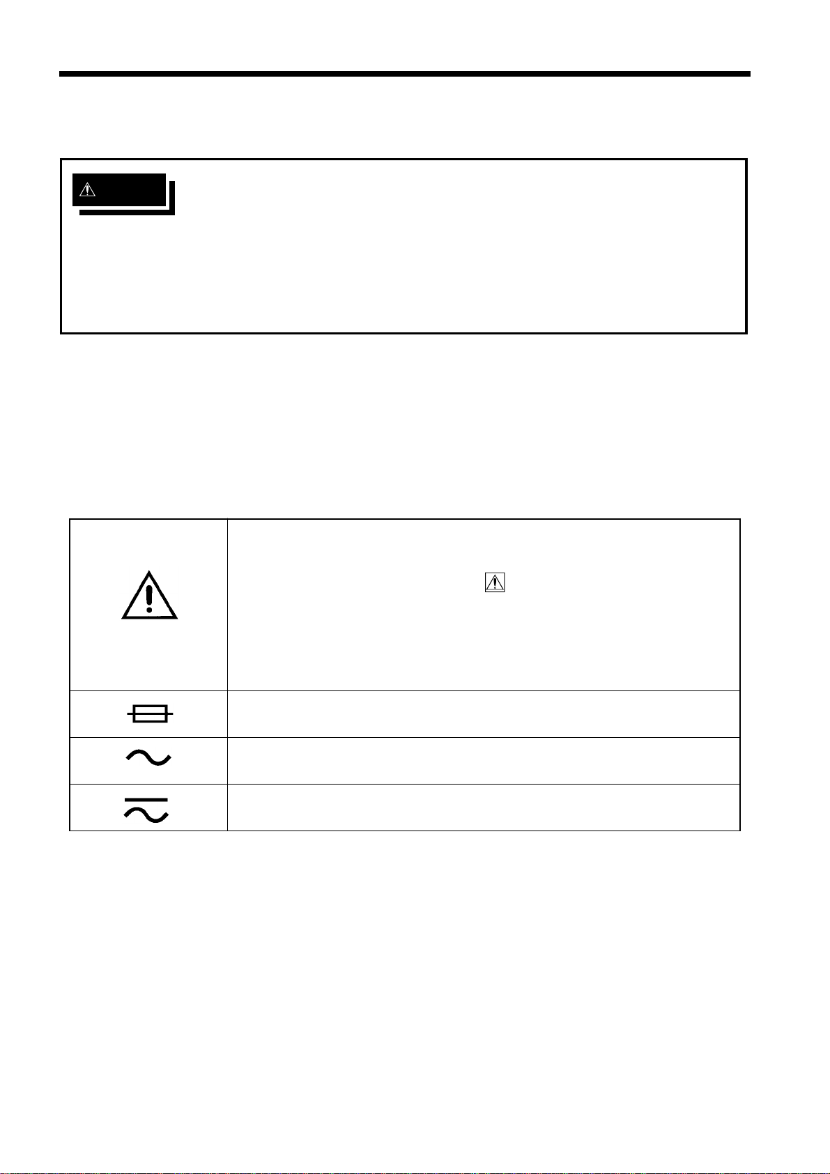
・This symbol is affixed to locations on the equipment where the
operator should consult corresponding topics in this manual
(which are also marked with the symbol) before using relevant
functions of the equipment.
・In the manual, this mark indicates explanations which it is
particularly important that the user read before using the
equipment.
Indicates a fuse.
Indicates AC (Alternating Current).
Indicates both DC (Direct Current) and AC (Alternating Current).
Safety Notes
This Instruction Manual provides information and warnings essential for
operating this equipment in a safe manner and for maintaining it in safe
operating condition. Before using this equipment, be sure to carefully read the
following safety notes.
Safety symbols
iii
────────────────────────────────────────────────────
Safety Notes
────────────────────────────────────────────────────
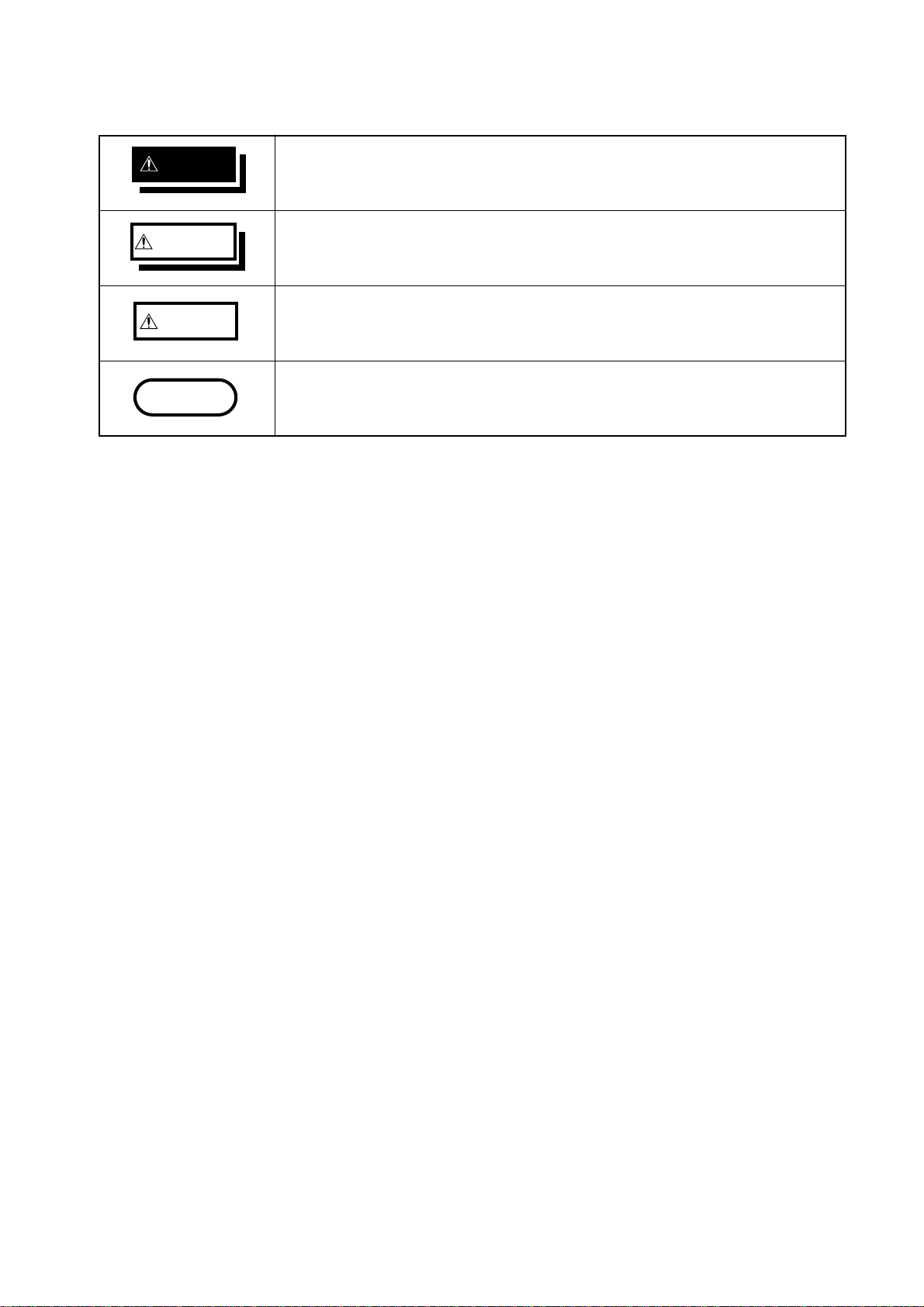
DANGER Indicates that incorrect operation presents extreme danger of
accident resulting in death or serious injury to the user.
WARNING Indicates that incorrect operation presents significant danger of
accident resulting in death or serious injury to the user.
CAUTION Indicates that incorrect operation presents possibility of injury to the
user or damage to the equipment.
NOTE Denotes items of advice related to performance of the equipment or
to its correct operation.
The following symbols are used in this Instruction Manual to indicate the
relative importance of cautions and warnings.
iv
────────────────────────────────────────────────────
Notes on Use
────────────────────────────────────────────────────
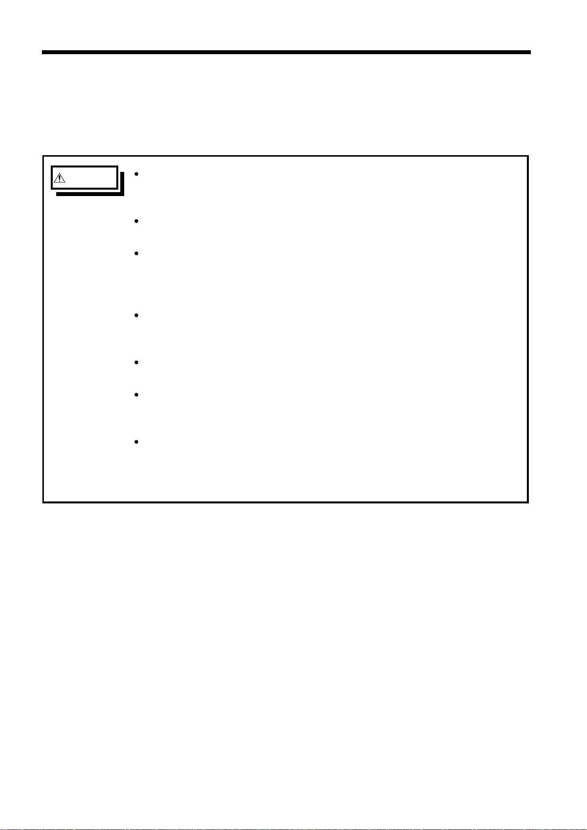
WARNING Before turning on the power, make sure that the voltage of the power
supply being used matches the supply voltage indicated on the rear
panel of the unit.
If an attempt is made to use an improper supply voltage, there is danger
of damage to this unit and of life-threatening risk to the operator.
The unit is constructed so as to be connected to a ground line via a
three-core power cord that is supplied with the unit. In order to avoid
electric shock, connect the unit to a properly grounded (3-pin) outlet
using the power cord provided.
The interior of the unit contains some components which are subject to
high voltage, and therefore dangerous. Absolutely do not remove the
cover panel.
To prevent electric shock, do not allow the unit to become wet and do
not use the unit when your hands are wet.
The unit should always be operated indoors in a range from 0℃to 40℃
and 30% to 90% RH. Do not use the unit in direct sunlight, dusty
conditions, or in the presence of corrosive gases.
Only use fuses of the specified type that is rated for the specified
current and voltage. Using a fuse that does not meet the specifications
or shorting the fuse holder may cause an accident that might result in
injury or death. (Specified fuse: 250 V T3.15 AL)
Notes on Use
In order to ensure safe operation and to obtain maximum performance from
the unit, observe the cautions listed below.
v
────────────────────────────────────────────────────
Notes on Use
────────────────────────────────────────────────────
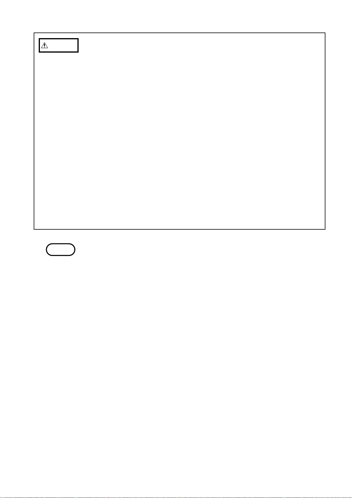
CAUTION ・Before using the unit, make sure that the sheathing on the probes (9296 or
9297) is not damaged and that no bare wire is exposed. If there is damage,
using the unit could cause electric shock. Contact your dealer or HIOKI
representative.
・In order to avoid electric shock, turn off the power to all devices before
plugging in or unplugging the measurement network or RS-232C connector.
・When unplugging the power cord from the power receptacle or from the unit,
grasp the plug, not the cord, in order to avoid damaging the cable.
・To avoid damaging the probes, do not bend or pull the probes.
・Use caution when taking measurements in circuits where the power lines are
hot.
・Take care not to block the ventilation openings on the sides of the unit.
・For safety reasons, only use the optional 9296 or 9297 probe for
measurement.
・To avoid damage to the unit, do not subject the equipment to vibrations or
shocks during transport or handling. Be especially careful to avoid dropping
the equipment.
・Do not insert a board other than optional interface boards into the Interface
slot. The unit software or calibration data may be lost.
・In the event that the equipment malfunctions in any manner during use, turn
off the power immediately, and contact your dealer or HIOKI representative.
NOTE Do not use the unit near any device which generates strong electromagnetic
radiation or near a static electrical charge, as these may cause errors.
vi
────────────────────────────────────────────────────
Contents and Indications of this Manual
────────────────────────────────────────────────────
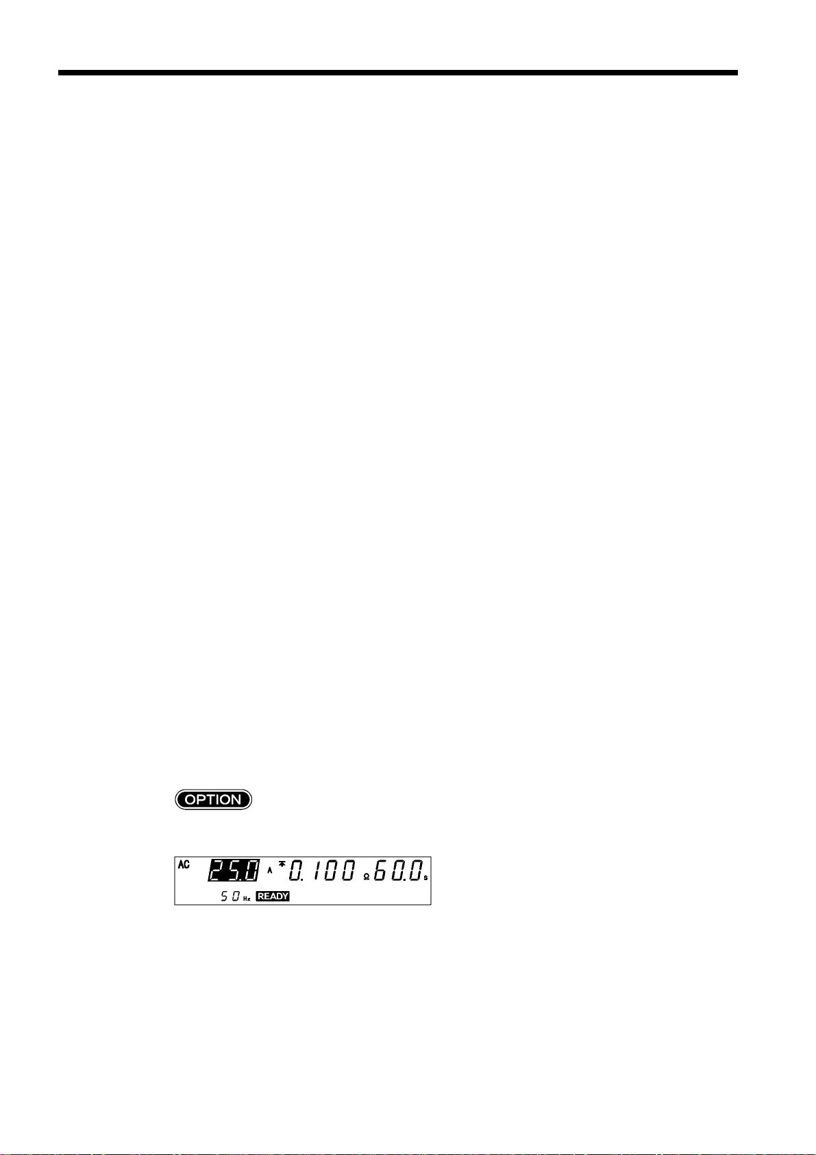
Indicates that settings can be made for optional functions.
For more information, see Chapter 4, "Optional Function."
In this Instruction Manual, the flashing area of the screen is
represented in reverse mode.
In this figure, for example, the current value of 25.0 A flashes.
Indications in the Instruction Manual
Contents and Indications of this Manual
Chapter 1: Overview
Describes an overview, features, and the names and functions of
the parts of the unit.
Chapter 2: Testing Arrangements
Describes particulars of testing arrangements.
Chapter 3: Testing Method
Describes procedures for setting, testing, and test results
judgement.
Chapter 4: Optional Functions
Describes procedures for setting optional functions.
Chapter 5: Saving/loading Preset Values
Describes procedure for saving and loading test values.
Chapter 6: External I/O
Describes use of the external I/O.
Chapter 7: Maintenance, Inspection and Ultimate Disposal
Covers the maintenance and inspection, fuse replacement, and
ultimate disposal.
Chapter 8: Specifications
Contains the unit specifications such as the general specifications,
measurement accuracy, etc. of the unit.
Chapter 9: Appendix
Covers the options of the unit and standards.
Other manuals for 3157
1
Table of contents
Other Hioki Test Equipment manuals

Hioki
Hioki RM3543 User manual

Hioki
Hioki FT6031-50 User manual

Hioki
Hioki 9261 User manual

Hioki
Hioki FT3470-51 User manual

Hioki
Hioki 3030-10 User manual

Hioki
Hioki ST5680 User manual

Hioki
Hioki RM3542 User manual

Hioki
Hioki 3805-50 User manual

Hioki
Hioki HiLogger 3145-20 User manual

Hioki
Hioki RM3543 User manual


Popular Test Equipment manuals by other brands


PCB Piezotronics
PCB Piezotronics 8159-0112A Installation and operating manual

BW Technologies
BW Technologies MicroDock II user manual

Sun Nuclear
Sun Nuclear 1027 user guide

Biomark
Biomark HPR LITE READER user manual

Ashcroft
Ashcroft ATE-100 operating manual

Rohde & Schwarz
Rohde & Schwarz RTA4000 user manual