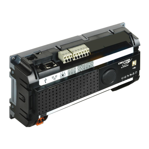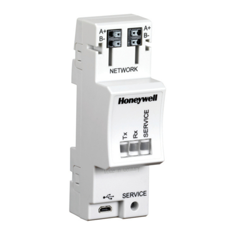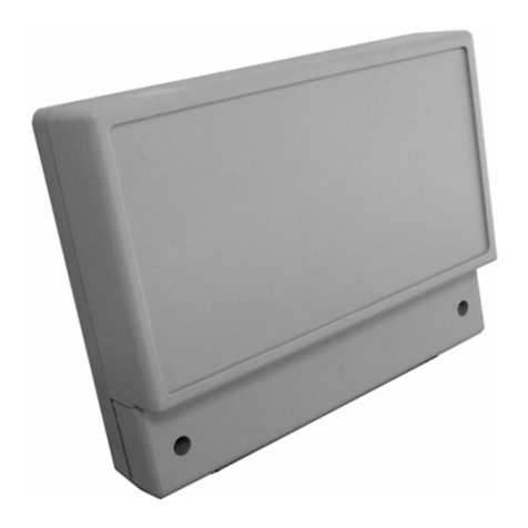
QS7800B NETWORK INTERFACE CONTROLBUS™ MODULE FOR MULTI-DROPPING 7800 SERIES RELAY MODULES
3 65-0227—2
3. Installer must be a trained, experienced service
technician.
4. Check out the product after installation, as provided in
the Q7700 Net ork Interface Unit instructions, form 63-
2278 and S7810B instructions, form 65-0228.
5. Make sure that only the manufacturer makes repairs.
6. If trouble develops, disconnect the equipment from the
modem and determine the cause of the fault.
Reconnect only hen the problem is corrected.
WARNING
.Electrical Shock Hazard.
Can cause severe injury, death or equipment
damage.
Disconnect po er supply before beginning installation
to prevent electrical shock and equipment damage.
More than one po er supply disconnection can be
involved.
Humidity
Install the Net ork Interface Unit here the relative humidity
never reaches the saturation point. The Net ork Interface
Unit is designed to operate in an 85 percent relative humidity
continuous noncondensing moisture environment.
Condensing moisture can result in improper operation.
Vibration
Do not install the Net ork Interface Unit here it can be
subjected to excessive vibration in excess of 0.5G continuous
maximum vibration.
Weather
The Net ork Interface Unit is not designed to be eather
tight. When installed outdoors, provide protection for the
Net ork Interface Unit.
Mounting the Network Interface Plug-in Card
For installation dimensions, see Fig. 1.
1. Mount the ControlBus™ Module in the Net ork
Interface Unit (see Fig. 2). Do not mount the Net ork
Interface Unit ith the Interface ControlBus™ Module
edge connector slots facing do n.
2. Insert the ControlBus™ Module ith the electrical
connector facing out from the Net ork Interface Unit.
3. Grasp the ControlBus™ Module and align the plug-in
edge card ith the connector in the bottom of the
Net ork Interface Unit.
4. Firmly insert the ControlBus™ Module into the Net ork
Interface Unit.
5. Select a location that can support the Net ork Interface
Unit. Be sure to allo clearances for servicing, installing
and removing the iring compartment cover, Net ork
Interface Unit cover, electrical connectors and
ControlBus™ Modules.
a. Allo for an additional 2-1/2 inches (64 mm)
minimum belo the Net ork Interface Unit for
electrical connector installation.
b. Allo for an additional 1-1/2 inches (38 mm)
minimum on each side for electrical housing cover
insertion and iring.
6. Remove the ControlBus™ Module using the ire loop;
grasp the ControlBus™ Module firmly and pull the
module from the Net ork Interface Unit.
WIRING
Wiring Requirements
WARNING
Electrical Shock Hazard.
Can cause severe injury, death or equipment
damage.
1. Wiring must comply ith all applicable codes,
ordinances and regulations.
2. Refer to Fig. 6 for proper system iring.
3. Do not plug or unplug any Net ork Interface Unit
ControlBus™ Module or electrical connectors ith
the po er on. Make sure that po er is off to protect
against equipment damage.
1. All iring must comply ith all applicable electrical
codes, ordinances, and regulations.
2. Recommended ire size and type for ControlBus™
communication is shielded 22 AWG t isted pair cable
(Belden 8723 or equivalent). Terminal identification
numbers and letters are sho n in Table 1.
Ta le 1. QS7800B and S7810B Terminals
and Identification.
3. Wire Routing:
a. Do not route the ControlBus™ cable in conduit ith
line voltage circuits.
b. Do not route the ControlBus™ cable close to the
ignition transformer.
c. Route the ControlBus™ cable outside of conduit if
properly supported and protected from damage.
d. Route the ControlBus™ cable so that all devices are
connected in a daisy chain configuration. See Fig. 6.
4. Maximum ire lengths can be 4000 ft (1219 m) for the
ControlBus™ RS-485 interface under ideal conditions.
Procedure
1. Refer to Fig. 6 for proper iring.
2. Be sure that po er is removed from the control panel by
opening the main disconnect before beginning iring to
the electrical connectors. More than one disconnection
can be involved.
3. Select the location of the Net ork Interface Unit to be
mounted:
Signal QS7800B
Terminals S7810B
Terminals
Multi-Drop Data+ a 7
Multi-Drop Data- b 8
Multi-Drop Ground c 6
