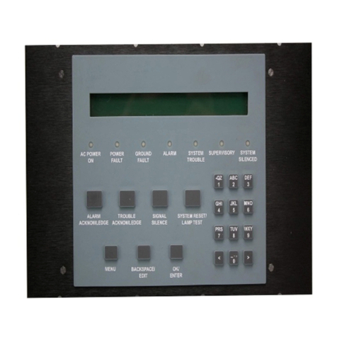
MA-2000
M-167.1-MA2000-EN / 06.2022 3
Contents
1GENERAL / APPLICATION ....................................................................................................................................................................................... 5
1.1 Associated Documents....................................................................................................................................................................................... 5
1.2 Precautions ................................................................................................................................................................................................................. 6
1.2.1 NATIONAL STANDARDS ..................................................................................................................................... 7
1.3 EN 54: Information.................................................................................................................................................................................................7
2TRANSPORT DAMAGE INSPECTION ............................................................................................................................................................... 8
3GENERAL DESCRIPTION.......................................................................................................................................................................................... 9
4ASSEMBLY AND INSTALLATION INFORMATION...............................................................................................................................10
4.1 MA-2000 dimensions....................................................................................................................................................................................... 11
4.2 MA-2000 Flush Mount....................................................................................................................................................................................13
4.3 Labels for the control panel.......................................................................................................................................................................... 14
5SPECIFICATIONS.......................................................................................................................................................................................................... 15
5.1 Earthing.......................................................................................................................................................................................................................15
5.2 Main power supply ..............................................................................................................................................................................................15
5.3 Power supply ...........................................................................................................................................................................................................15
5.4 Battery charger section.................................................................................................................................................................................... 15
5.4.1 Batteries.................................................................................................................................................................. 15
5.4.2 Batteries Installation ......................................................................................................................................... 16
5.4.3 Power supply and battery operation........................................................................................................... 16
5.4.4 Mains and Batteries connection.................................................................................................................. 17
6SYSTEM COMPONENTS........................................................................................................................................................................................18
6.1 MA-2000 CPU Board ........................................................................................................................................................................................19
6.2 MA-2000 PSU Board.........................................................................................................................................................................................20
6.2.1 Terminal Board AW80US0 .............................................................................................................................. 21
6.3 Relay outputs ..........................................................................................................................................................................................................22
6.3.1 Instructions to setting the relay outputs as NO / NC or Supervised ........................................... 22
6.3.2 General Fault relay.............................................................................................................................................. 23
6.3.3 General Alarm relay ............................................................................................................................................ 23
6.3.4 USR1 and USR2 relays ..................................................................................................................................... 24
6.3.5 Sounder connection - controlled output.................................................................................................. 25
6.4 OPTIONAL CARD .................................................................................................................................................................................................26
6.4.1 MA-BST-C (CAN-BUS amplifier card)........................................................................................................ 26
6.4.2 Board Assembly MA-BST-C............................................................................................................................ 27
7MA-2000 NETWORK WIRING EXAMPLE NODE-TO-NODE CONNECTION.................................................................. 28
7.1 MA-2000 Network Wiring Example Single CAN-BUS amplifier card installed
on HLSPS25 EN 54-4 PSU ..........................................................................................................................................................................28
7.2 MA-2000 Network Wiring Example Multiple CAN-BUS amplifier card installed
on HLSPS25 EN 54-4 PSU .......................................................................................................................................................................... 29
8COMMUNICATION LINES WITH DETECTORS / MODULES......................................................................................................30
8.1 Screen Termination ............................................................................................................................................................................................31
8.1.1 Example of closed line (style 6 Loop) ........................................................................................................ 31
8.2 Test procedure for detection lines ...........................................................................................................................................................32
8.3 System Test and Commissioning ............................................................................................................................................................33
