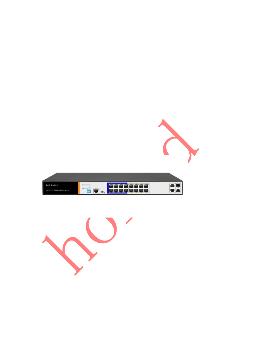
Hored PS3016 User manual

User manual
PS3016
16 Port Layer 2 PoE Switch

1
Installation manual introduction
The Product installation manual mainly describes PS3016SPoE switch
hardware features, installation methods, and precautions during the
installation
This manual includes the following chapters:
Chapter 1: Product Introduction. Briefly describes the basic
features, Detailed hardware & software specifications of the switch
and the appearance details.
Chapter 2: Product Installation. Guide the switch hardware
installation methods and precautions.
Chapter 3: Hardware Connections. Guide the connection between
switches and other devices and precautions.
Chapter 4: Packaging and product usage suggestions.

2
Chapter 1: Product Introduction
1.1 Products description
PS3016S is managed PoE switch for security transmission and
WIFI coverage, meet the need of PoE power supply for WIFI AP,
IP-camera, WIFI bridge, IP phones and other types of equipment.
New generation of high-performance hardware and software
platforms are used, providing flexible, cost-effective full Gigabit
access and uplink ports, complete security mechanisms, improved
ACL / QoS strategy and rich VLAN capabilities. It is easy to
manage and maintain, meet the users' requirements for network
equipment easy to manage, high security and low cost.
Supporting Apollo Cloud One-stop Management Platform,
realizing status checking and management monitoring functions,
suitable for campus, Hotel and enterprise park network access,
convergence, core multi-application scenarios

3
1.2 Product Features
Full Gigabit Port
16 1000Mbps RJ45 ports (support PoE power supply) with 2
Gigabit SFP ports, Data transmission is not jammed.
Realtek chip, the performance is more stable and powerful
Realtek high-performance chip can greatly improve network
data processing rate
Convenient operation
·AI VLAN mode: Separating 1-8 ports from each other, can
effectively restrain network storm and improve network
performance.
·AI Extend mode: Designed for monitoring application
scenarios, 1-8 ports support 250 meters long distance power
supply.
·AI PoE mode:automatically check, reboot the device while
find it fake dead
·AI QoS mode:video data first, more fluent transmission
Support Apollo Cloud Platform One-stop Management
Support cloud platform for resource visualization management
of switches and downloaded PD devices, make operation and

4
maintenance management easy
1.3 product specification
Hardware Specifications
Chipset
RealtekHigh Performance Chipset
Flash
16MB
RAM
128M DDR
Port
16 10/100/1000Mbps RJ45 ports
210/100/1000Mbps RJ45ports
2 Gigabit SFP ports
1 Console port
PoE
16 10/100Mbps RJ45 port support
PoE+
Max 150W
Single port max 46W
LEDs
18 Link/Act LEDs
16 POE LEDs
1 Power LED
1 SYS LED
Performance
Forwarding mode: store and forward
Switch Volume (Full-duplex) :7.2Gbps
Packet forwarding rate:5.36Mpps
8K MAC address table
lightning protection
±6KV
ESD
No barrier: ±6KV Air:±8KV

5
Input
100-240V/50-60Hz
Dimension
(L×W×H)
440mm×180mm×44mm
Software Specifications
Network standard
IEEE 802.3: Ethernet Media Access Control
(MAC) protocol
IEEE 802.3i:10BASE-T Ethernet
IEEE 802.3u:100BASE-TX fast Ethernet
IEEE 802.3ab:1000BASE-T gigabit Ethernet
IEEE 802.3z:1000BASE-X gigabit Ethernet
(fiber)
IEEE 802.3ad: comply link aggregation
standard
IEEE 802.3x: flow control
IEEE 802.1p: About the traffic priority of
the second layer of Qos / Cos protocol
(multicast filtering)
IEEE 802.1q:VLAN Bridge operation
IEEE 802.1d:STP spanning tree
IEEE 802.1s:MSTP spanning tree
IEEE 802.1w:RSTP spanning tree
IEEE 802.3af
IEEE 802.3at
Shortcut function
One key VLAN
One key Exnted(1-8 port 250meters PoE
distance)

6
One key QoS (Video priority)
One key AI power supply
DHCP
DHCP Snooping
VLAN
Support 4K VLAN
Support 802.1Q VLAN、Port VLAN、Voice
VLAN
MAC address table
Comply the IEEE 802.1d standard
Support MAC address learning and aging
automatically
Support static, dynamic, filter address table
Safety
Password protection
Support based on the port number, IP
address, MAC address restrictions on user
access
Support HTTPS、SSL V3、TLS V1、SSH
V1/V2
Based on user rating management and
password protection
Support IP-MAC-PORT
Support ARP protection, IP sources
protection, DoS protection
Support DHCP Snooping、DHCP attack
protection

7
Support 802.1X AAA
Support port security, port isolation
Support CPU protection
PoE
Support setting the PoE port priority
Support viewing POE Chip Status
Support setting PoE power supply period
Support setting port power
Access control (ACL)
Support L2(Layer 2)~L4(Layer 4) packet
filtering function
Support port mirroring, port redirection,
flow rate limit, QoS re-marking
QoS
Support 8 port queue
Support port priority, 802.1p priority, DSCP
priority
Support SP、RR、WRR、WFQ Priority
scheduling algorithm
Support automatically identify, manage
and acquire of connected equipment
information
Multicast
Support IGMP v1/v2 Snooping
Support static multicast
Support multicast VLAN
Support multicast filtering, message statistics,
unknown multicast discarding

8
Spanning Tree
Support STP(IEEE 802.1d),RSTP(IEEE
802.1w) and MSTP(IEEE 802.1s) protocol
Support loop protection, BPDU protection
Storm suppression
Support for multicast suppression
Support broadcast suppression
Support for unknown unicast suppression
Link aggregation
Support static aggregation
Support dynamic aggregation
Support IP, MAC, hybrid load balancing
mode
Supports up to 32 aggregation groups
IPv6
Support IPv6 Ping、IPv6 Tracert、IPv6 Telnet
Support IPv6 SSH 、IPv6 SSL
Management and
maintenance
Support WEB management(HTTP、
HTTPS、SSL V3)
Support CLI(Telnet、SSH V1/V2,local
serial port)
Support SNMP V1/V2/V3
Support LLDP、RMON
Support SNMP
Support ARP Protection, IP Source

9
protection、DoS protection
Support CPU monitor、memory
monitoring
Support system log
Support Ping, Tracert detect cable testing
1.4 Appearance
Front Panel
Including indicators, RJ45 port, DIP switch, RST button, SFP port,
CONSOLE port, as shown below
indicator
PS3016S The indicator working status is shown as the
following table
PS3016S The indicator working status is shown as the

10
following table
Indicators
Title
Color
Work
status
Description
POWER
Power
indicator
Red
Solid
Power is normal
Off
No power, the power
switch is not turned
on, power supply is
abnormal
POE
POE
power
indicator
Yellow
Solid
The corresponding
RJ45 port is connected
to the powered device
and the power supply
is normal
Off
The corresponding
RJ45 port is not
connected to the
powered device or the
power supply is
abnormal
LINK/ACT
Connecti
on
indicator
Green
Blinkin
g
A valid link is
established
Off
An invalid link is
established
SYS
System
indicator
Green
Blinkin
g
System is functioning
properly
Off
System is functioning
improperly Software is
damaged

11
SFP
SFP
indicator
Green
Blinkin
g
A valid link is
established on the SFP
port
Off
An invalid link is
established on the SFP
port
Shortcut button
QOS: Improve video data processing capabilities and
improve the monitoring of Caton and Mosaic
phenomena in the network
Extend: 1-8 port rate down to 10Mbps, but the
transmission distance up to 250 meters
VLAN: Isolating ports 1-8 from each other, suppress
network storms effectively and improve network
performance
AI power supply: Detect PD, power failure and restart
dead equipment
RJ45 Port
PS3016S with 16 10/100/1000Mbps PoE port, all ports
support IEEE802.3af and IEEE802.3at standard
When the switch mode of operation is CCTV mode, 1-8
port can support 250 meters power supply

12
SFP Port
PS3016S provides 4 Gigabit SFP optical ports (SFP1,
SFP2), can be inserted into the Gigabit SFP module
RST Button
When the switch is powered on, press the button with
the needle to release the device and enter the
restarting state. When the SYS lamp restarts, the device
restarts. When the switch is powered on, press and hold
the button for more than 5s to release the button and
enter the reset state. When SYS is re-lit, the device is
reset successfully
Console port
Console port used to connect to computer or other
terminal to manage or configure the switch.
Back Panel
Including: power socket, ground terminal

13
Power socket
A 100-240VAC 50/60 Hz power receptacle for
accommodating the supplied power cord
Ground terminal
Please use the grounding wire to prevent lightning. To
avoid product lightning strikes and extend product
life
Chapter2 Hardware connection
2.1 RJ45 port connection
Connect the RJ45 port of the switch and the corresponding network
device via cables, the POE power supply function of the switch is
default enabled on the downlink port of the switch, which can be
used for IEEE802.3af or IEEE802.3at standards powered devices such
as APs, bridges, and network cameras

14
Note:
When the switch connected workstations, servers, routers or
other ethernet devices the cable length should be within 100
meters;
The Auto-MDI / MDIX ethernet interface is enabled by default.
Category 5,the standard network cable or crossover cable can be
used for Ethernet connection.
Do not connect the RJ45 port to the phone line
2.2 SFP Port connection
PS3016S SFP port only support Gigabit fiber module.
Recommended use of standard SFP module products
The process of installing a fiber module on a switch is as follows:
1、 grasp the optic fiber module from the side, insert it
smoothly along the SFP port slot until the optic fiber module and
switch are in close contact;

15
2、confirm the Rx and Tx ports of the fiber module when
connecting, insert one end of the fiber into the Rx and Tx ports
correspondingly, ensure that the Tx and Rx ends of the interface
are connected correctly and the other end of the fiber is
connected to another device;
3、please check the corresponding indicator light status after
power on. If the light blinking that the link is properly connected,
if the light is off , the link is failure, please check the line to
confirm that the corresponding equipment is enabled.
Note:
DO NOT excessive bending fiber, the radius of curvature should
not be lessthan 10cm;
Ensure the cleanliness of the fiber surface;
Please DO NOT look directly into the optical fiber connector with
your eyes as this may cause eye injury
2.3 Check before power on
Check whether the outlet power supply meets the switch
specifications;
Check the power, switches, racks and other equipment have been
properly grounded;
Check whether the switch and other network devices are
connected properly

16
2.4 Device initialization
The switch automatically initializes when the power switch is
turned on.
Indicator will appear the following situation:
After the power is turned on, the power indicator remains on, the
other indicator is off at this time;
After about 1 second, all lights except for the power light turn on
for about 35 seconds and then turn off; when the SYS light goes
flashing, the system runs normally
Port LEDs indicates the connection status of each port, indicating
that the switch has started to work normally
Chapter3 Installation
3.1 Installation Precautions
Note:To avoid improper use of equipment damage and
personal injury, please observe the following precautions
Installation safety precautions
The power should be kept off during the installation, while
wearing anti-static wrist, and to ensure well touch between
anti-static wrist and skin to avoid potential safety hazard;
The switch just works normally when it is powered by the
correct power supply. Make sure that the power supply

17
voltage matches the voltage indicated by the switch
Before powering on the switch, make sure that the power
circuit is not overloaded, which may affect the normal
operation of the switch and even cause unnecessary damage
To avoid the risk of electric shock, do not open the case while
the switch is working. Do not open the case even when it is
not powered
Before cleaning the switch, unplug the switch from the power
cord and do not wipe it with wet cloth. Do not wash it with
liquid
Temperature and humidity
To ensure the long-term stability working of the switch , please
maintain a certain temperature and humidity environment.
High or low humidity easily lead to leakage of insulation
materials, deformation and even the corrosion of metal parts,
the temperature is too high will accelerate the aging process
of insulating materials, seriously affecting the service life of
equipment. The normal operation of this series of switches
and storage temperature / humidity are as follows
Environmental
description
temperature
Relative humidity
Working
environment
0℃~40℃
10%~90% RH no
condensation
Storage
environment
-40℃~70℃
5%~90% RH no
condensation

18
Altitude
Products with this logo are only for safe use in areas below
2000m altitude
Dust-proof
Dust on the switch surface will cause electrostatic adsorption,
poor contact of the metal contacts. Although the device itself
has done some measures in anti-static, but when the static
electricity exceeds a certain intensity, it will still cause fatal
damage to the electronic components on the internal circuit
board.
In order to prevent static electricity from affecting the normal
operation of the equipment, please note the following:
1. Regular dust, keep the indoor air clean;
2. Make sure the equipment is well grounded to ensure
smooth transfer of static electricity
Electromagnetic interference
Electromagnetic interference have an impact on the device
capacitance, inductance and other electronic components by
capacitance, inductive coupling, impedance coupling and
other conductive, in order to reduce the adverse effects
caused by electromagnetic interference, please note the
following:
1. Power supply system to take the necessary anti-grid
interference measures;

19
2. Switches should be far away from high-frequency high-
power, high-current devices, such as wireless
transmitters;
3. If necessary, take electromagnetic shielding measures
Lightning protection
When a lightning strike occurs, a strong current will be
generated in an instant cause fatal damage to electronic
equipment. To achieve better lightning protection, please note
the following:
1. Make sure the rack and the ground to maintain good
contact;
2. Make sure the power outlet is in good contact with the
earth;
3. Reasonable wiring, to avoid the internal sense ray;
4. Outdoor wiring, it is recommended to use the signal
lightning protection device
Installation desk requirement
Regardless of whether the switch is installed in a rack or on
another horizontal workbench, be aware of the following:
1. Make sure the rack or workbench is stable, strong, and
can withstand at least 5.5Kg weight;
2. Make sure the rack has a good cooling system, or
maintain good indoor ventilation;
3. Make sure the rack is well grounded, the power outlet
and switch are within 1.5 meters
Prepare tools for installation
You may need to use a screwdriver during installation, electrostatic
Table of contents
Other Hored Switch manuals

Hored
Hored IS108GPS-4F User manual

Hored
Hored IS104GPS-2F User manual

Hored
Hored S5700-24G-24F-4TF User manual

Hored
Hored PS3024GS User manual

Hored
Hored S5700-12G-12F User manual

Hored
Hored S5700-24F-8G-4TF User manual

Hored
Hored IS104GS-2F User manual

Hored
Hored AI606 User manual

Hored
Hored PS2024G User manual

Hored
Hored PS3024S User manual

Hored
Hored PS3016S User manual

Hored
Hored PS2010G User manual

Hored
Hored AI2010GX User manual

Hored
Hored IS108S-4F User manual

Hored
Hored PS3016GS User manual

Hored
Hored DF5700-24GP-4TF User manual

Hored
Hored AI1010G-Apollo User manual

Hored
Hored S5700-24G-4F-4TF User manual

Hored
Hored AI106G-Apollo User manual

Hored
Hored AI106 User manual