HT EV-TEST100 User manual

USER
MANUAL
100
MANUAL

Rel. 3.00 - 03/10/222

Rel. 3.00 - 03/10/22 3
IT
EN
ES
DE
FR
PT
MANUALE D’USO
USER MANUAL
MANUAL DE INSTRUCCIONES
BEDIENUNGSANLEITUNG
MANUEL D’UTILISATION
MANUAL DE INSTRUÇÕES

Rel. 3.00 - 03/10/224
PRECAUZIONI E MISURE DI SICUREZZA 7
DESCRIZIONE GENERALE 8
PREPARAZIONE ALL’UTILIZZO 8
NOMENCLATURA 9
ISTRUZIONI OPERATIVE 10
MANUTENZIONE 12
SPECIFICHE TECNICHE 12
ASSISTENZA 13
DESCRIZIONE DELLO STRUMENTO 54
PRECAUTIONS AND SAFETY MEASURES 15
GENERAL DESCRIPTION 16
PREPARATION FOR USE 16
NOMENCLATURE 17
OPERATING INSTRUCTIONS 18
MAINTENANCE 20
TECHNICAL SPECIFICATIONS 20
ASSISTANCE 21
INSTRUMENT DESCRIPTION 54
PRECAUCIONES Y MEDIDAS DE SEGURIDAD 23
DESCRIPCIÓN GENERAL 24
PREPARACIÓN A LA UTILIZACIÓN 24
NOMENCLATURA 25
INSTRUCCIONES OPERATIVAS 26
MANTENIMIENTO 28
ESPECIFICACIONES TÉCNICAS 28
ASISTENCIA 29
DESCRIPCIÓN DEL INSTRUMENTO 54
IT
EN
ES

Rel. 3.00 - 03/10/22 5
DE
FR
PT
ALLGEMEINE BESCHREIBUNG 32
VORBEREITUNG ZUM GEBRAUCH 32
NOMENKLATUR 33
BETRIEBSANLEITUNGEN 34
WARTUNG 36
TECHNISCHE DATEN 36
SERVICE 37
BESCHREIBUNG DES GERÄTS 54
PRECAUTIONS ET MESURES DE SECURITE 39
DESCRIPTION GENERALE 40
PREPARATION A L’UTILISATION 40
NOMENCLATURE 41
INSTRUCTIONS D’UTILISATION 42
MAINTENANCE 44
SPECIFICATIONS TECHNIQUES 44
SERVICE 45
DESCRIPTION DE L'INSTRUMENT 54
PRECAUÇÕES E MEDIDAS DE SEGURANÇA 47
DESCRIÇÃO GERAL 48
PREPARAÇÃO PARA A SUA UTILIZAÇÃO 48
NOMENCLATURA 49
INSTRUÇÕES DE FUNCIONAMENTO 50
MANUTENÇÃO 52
ESPECIFICAÇÕES TÉCNICAS 52
ASSISTÊNCIA 53
DESCRIÇÃO DO INSTRUMENTO 54

Rel. 3.00 - 03/10/226
EV-TEST 100
1PRECAUZIONI E MISURE DI SICUREZZA 7
1.1. Istruzioni preliminari 7
2DESCRIZIONE GENERALE 8
3PREPARAZIONE ALL’UTILIZZO 8
3.1. Controlli iniziali 8
3.2. Alimentazione dell'adattatore 8
3.3. Conservazione 8
4NOMENCLATURA 9
4.1 Descrizione dell’adattatore 9
4.2 Descrizione funzioni selettore PP STATE 9
4.3 Descrizione funzioni selettore CP STATE 9
4.4 Descrizione funzioni selettore simulazione guasti 9
5ISTRUZIONI OPERATIVE 10
6MANUTENZIONE 12
6.1. Pulizia dell'adattatore 12
6.2. Fine vita 12
7SPECIFICHE TECNICHE 12
7.1. Accessori in dotazione 12
8ASSISTENZA 13
8.1. Condizioni di garanzia 13
8.2. Assistenza 13
9DESCRIZIONE DELLO STRUMENTO 54
IT

Rel. 3.00 - 03/10/22 7
EV-TEST 100
L’adattatore è stato progettato in conformità alla normativa IEC/EN61010-1,
relativa agli strumenti di misura elettronici. Per la Sua sicurezza e per evitare
di danneggiare L’adattatore, La preghiamo di seguire le procedure descritte
nel presente manuale e di leggere con particolare attenzione tutte le note
precedute dal simbolo . Prima e durante l’esecuzione delle misure attenersi
scrupolosamente alle seguenti indicazioni:
• Non eettuare misure in ambienti umidi.
• Non eettuare misure in presenza di gas o materiali esplosivi, combustibili o
in ambienti polverosi.
• Evitare contatti con il circuito in esame se non si stanno eettuando misure.
• Evitare contatti con parti metalliche esposte, con terminali di misura
inutilizzati, ecc.
• Non eettuare alcuna misura qualora si riscontrino anomalie nell’adattatore
come, deformazioni, rotture, fuoriuscite di sostanze, ecc.
• Prestare particolare attenzione quando si eettuano misure di tensioni
superiori a 25V AC in quanto è presente il rischio di shock elettrici.
Nel presente manuale e sull’adattatore sono utilizzati i seguenti simboli:
Attenzione: attenersi alle istruzioni riportate nel manuale; un uso improprio
potrebbe causare danni all’adattatore o ai suoi componenti
Adattatore con doppio isolamento
Tensione AC
Riferimento di terra
ISTRUZIONI PRELIMINARI
1.1
• L’adattatore può essere usato per misure di TENSIONE AC su installazioni con
CAT III 300V verso terra
• Non usare L’adattatore su utenze con caratteristiche diverse da quelle
riportate al § 7. La invitiamo a seguire le normali regole di sicurezze orientate
alla protezione contro tensioni pericolose e proteggere L’adattatore contro un
utilizzo errato
• Non eettuare misure su circuiti che superino i limiti di corrente e tensione
specicati
• Non eettuare alcuna misura qualora si riscontrino anomalie nell’adattatore
come, deformazioni, rotture, fuoriuscite di sostanze, mancate visualizzazioni
a display, ecc
PRECAUZIONI E
MISURE DI SICUREZZA
1IT
ATTENZIONE

Rel. 3.00 - 03/10/228
EV-TEST 100
CONTROLLI INIZIALI
3.1
L’adattatore, prima di essere spedito, è stato controllato dal punto di vista
elettrico e meccanico. Sono state prese tutte le precauzioni possibili anché
L’adattatore potesse essere consegnato senza danni. Tuttavia, si consiglia
comunque di controllare sommariamente l’adattatore per accertare
eventuali danni subiti durante il trasporto. Se si dovessero riscontrare
anomalie contattare immediatamente lo spedizioniere. Si consiglia inoltre di
controllare che l’imballaggio contenga tutte le parti indicate al § 7.1.1. In caso
di discrepanze contattare il rivenditore. Qualora fosse necessario restituire
l’adattatore, si prega di seguire le istruzioni riportate al § 8
Utilizzare l’adattatore solo nei modi specicati nel presente manuale d’uso al
ne di evitare possibili danneggiamenti
ALIMENTAZIONE DELL’ADATTATORE
3.2
L’adattatore è alimentato direttamente dalla stazione di ricarica tramite
cavo a spina incorporato.
CONSERVAZIONE
3.3
Per garantire misure precise, dopo un lungo periodo di conservazione,
attendere che l’adattatore ritorni alle condizioni normali (vedere il § 7)
DESCRIZIONE
GENERALE
PREPARAZIONE
ALL'UTILIZZO
2
3
Il modello EV-TEST100 è un adattatore progettato per l’interfacciamento
con le prese delle stazioni di ricarica delle auto elettriche (sistemi EVSE –
Electrical Vehicle Supply Equipment) al ne di eseguire test di sicurezza
elettrica di tali dispositivi. L’adattatore è in grado di simulare la presenza
di un veicolo elettrico al ne di misurare i segnali di tensione in uscita dalle
stazioni di ricarica e simulare condizioni di guasto. EV-TEST100 è utilizzabile
in abbinamento ai seguenti strumenti di verica della famiglia HT:
L’adattatore è caratterizzato dalle seguenti funzioni:
• Utilizzo per stazioni EVSE con modi di ricarica 2 e 3
• Cavo di prova con connettori di Tipo 1 (nazioni USA/MEX/JAP) e Tipo 2 (nazioni EU)
• Simulazione veicolo tramite Control Pilot (CP state)
• Simulazione capacità corrente cavo tramite Proximity Pilot (PP state)
• Simulazione condizione di guasto su PE (Fault PE)
• Simulazione condizione di guasto sul Control Pilot (Fault E)
• Controllo ecienza contatore energia interno stazione (sezione LOAD)
• Indicazioni a LED presenza fasi del sistema
• Terminali per collegamento a strumenti di verica HT
• Fusibile di protezione sulla sezione LOAD
• Test in accordo alle normative di riferimento IEC/EN61851-1 e IEC/EN60364-7-722
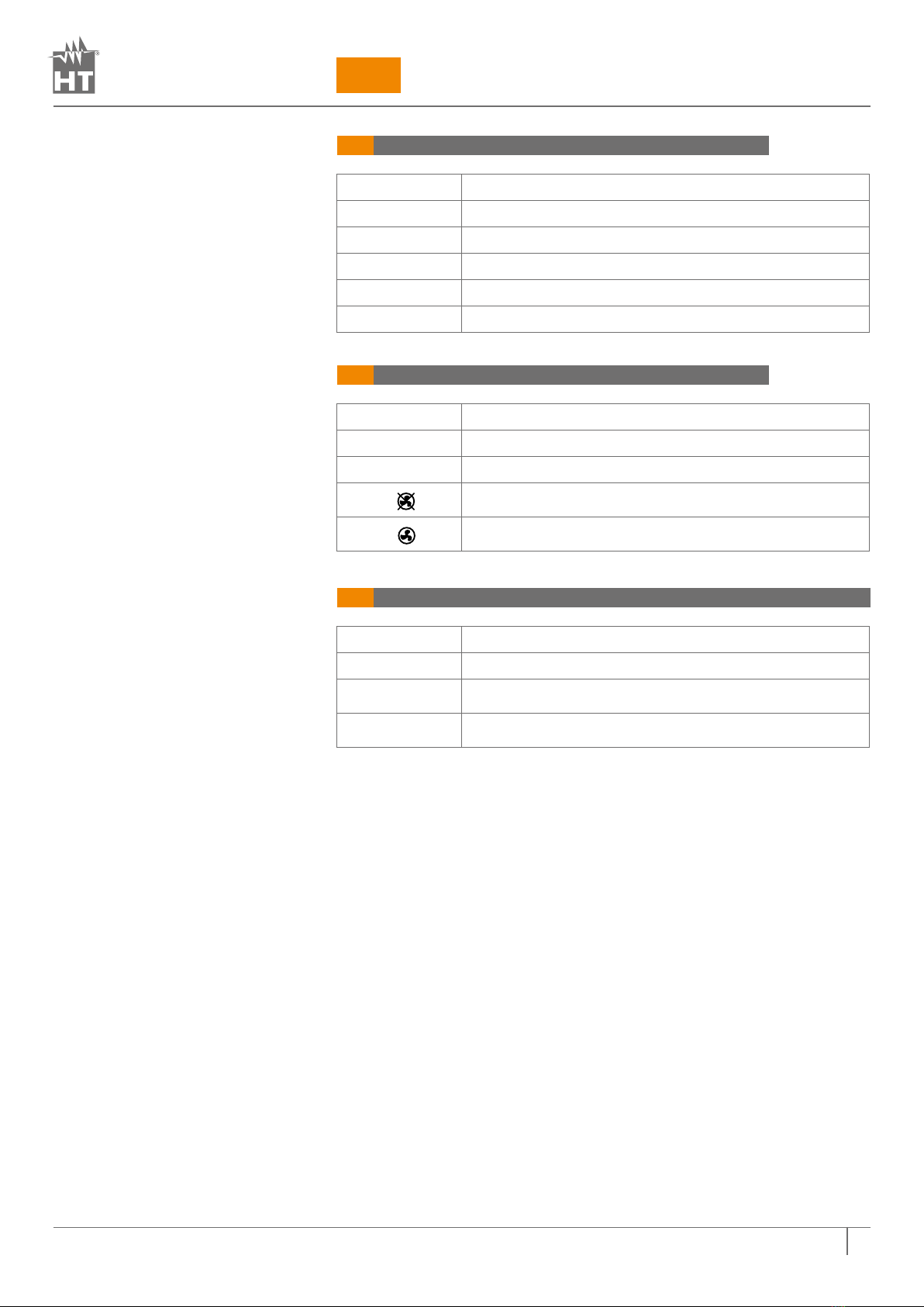
Modello (*) Tipologia
costruttiva Alimentazione EVSE Versione FW
MACROEVTEST
CAT IV 300V
Monofase
L-N-PE
Trifase
L1-L2-L3-N-PE
2.08
(o superiore)
COMBIG2
COMBIG3
COMBIG2PLUS
COMBITEST425EV
MT-300
COMBI521
SUPERCOMBIS
Monofase L-N-PE
Bifase L1-L2-PE
Trifase L1-L2-L3-N-PE
2.09
(o superiore)
ATTENZIONE
(*) L’elenco dei modelli disponibili può
variare senza preavviso. In caso di dubbi
contattare il servizio assistenza
Tabella 1: Elenco modelli compatibili con
adattatore EV-TEST100

Rel. 3.00 - 03/10/22 9
EV-TEST 100
DESCRIZIONE FUNZIONI SELETTORE PP STATE
4.1
DESCRIZIONE FUNZIONI SELETTORE CP STATE
4.2
DESCRIZIONE FUNZIONI SELETTORE SIMULAZIONE GUASTI
4.3
IT
NOMENCLATURA
4
Posizione Descrizione
NC Sistema EVSE non collegato
13A Sistema EVSE collegato con corrente massima 13A
20A Sistema EVSE collegato con corrente massima 20A
32A Sistema EVSE collegato con corrente massima 32A
63A Sistema EVSE collegato con corrente massima 63A
Posizione Descrizione
A Veicolo elettrico non collegato
BVeicolo elettrico collegato, non pronto per carica
C Veicolo elettrico collegato, pronto per carica,
ventilazione non richiesta
D Veicolo elettrico collegato, pronto per carica,
ventilazione richiesta
Posizione Descrizione
STATUS OK Nessuna simulazione di guasto presente
FAULT PE Simulazione condizione di guasto sul conduttore di
protezione PE (sistema EVSE non esegue ricarica)
FAULT E Simulazione condizione di guasto sul Control Pilot
(sistema EVSE non esegue ricarica)

Rel. 3.00 - 03/10/22
EV-TEST 100
ISTRUZIONI
OPERATIVE
5
TEST SUI SISTEMA EVSE CON CONNETTORE TIPO 2
5.1
1. Collegare l’adattatore all’ingresso In1 dello strumento multifunzione HT
tramite cavo C100EV fornito in dotazione (vedere Fig. 1 – parte 1)
2.Collegare i terminali L1, PE e N/L2 (il LED L2 è attivo solo nei sistemi Bifase)
(vedere Fig. 1 – parti 2, 3) dell’adattatore rispettivamente agli ingressi B1, B3
e B4 dello strumento multifunzione HT usando i cavi in dotazione allo stesso
strumento HT
3.Collegare il cavo a spina Tipo 2 (vedere Fig. 1 – parte 11) al sistema EVSE
4.Impostare il selettore PP STATE (vedere Fig. 1 – parte 5) in posizione NC
5.Impostare il selettore CP STATE (vedere Fig. 1 – parte 6) in posizione A
6.Impostare il selettore funzioni FAULT (vedere Fig. 1 – parte 7) in posizione
STATUS OK
7. Selezionare il modo “EVSE Test” sullo strumento multifunzione HT
8.Premere il tasto GO/STOP sullo strumento multifunzione HT e seguire la
procedura di test guidata (vedere relativo manuale d’uso)
Per le istruzioni dettagliate sull’uso dell’adattatore fare riferimento al
manuale d’uso dello strumento HT a cui deve essere collegato (vedere
Tabella 1)
TEST CONTROLLO EFFICIENZA CONTATORE ENERGIA
SISTEMA EVSE
5.1.1
L’adattatore consente di eseguire un test al ne di valutare l’ecienza del
contatore di energia interno al sistema EVSE Tipo 2. A tal ne è necessario:
1. Collegare un carico esterno con corrente max assorbita 10A AC ai terminali
di ingresso L, N/L2, PE (vedere Fig. 1 – parti 8 e 10) della sezione LOAD
2.Impostare i tre selettori nelle posizioni: STATUS OK, C o D (CP STATE), e 13A,
20A, 32A o 63A (PP STATE)
3.Fare riferimento alle istruzioni del sistema EVSE in prova per la lettura del
contatore
ATTENZIONE
Fig. 3: Uso su sistemi con cavo a
spina Tipo 2 per test su sistemi EVSE

Rel. 3.00 - 03/10/22
EV-TEST 100 IT
TEST SUI SISTEMA EVSE CON CONNETTORE TIPO 1
5.2
1. Collegare l’adattatore all’ingresso In1 dello strumento multifunzione HT
tramite cavo C100EV fornito in dotazione (vedere Fig. 1 – parte 1)
2.Collegare i terminali L1, PE e N/L2 (il LED L2 è attivo solo nei sistemi Bifase)
(vedere Fig. 2 – parti 2, 3) dell’adattatore rispettivamente agli ingressi B1,
B3 e B4 dello strumento multifunzione HT (vedere Tabella 1) usando i cavi in
dotazione allo stesso strumento HT
3.Collegare il cavo a spina Tipo 1 (vedere Fig. 2 – parte 11) al sistema EVSE
4.Impostare il selettore PP STATE (vedere Fig. 2 – parte 5) in posizione NC
5.Impostare il selettore CP STATE (vedere Fig. 2 – parte 6) in posizione A
6.Impostare il selettore funzioni FAULT (vedere Fig. 2 – parte 7) in posizione
STATUS OK
7. Selezionare il modo “EVSE Test” sullo strumento multifunzione HT
8.Premere il tasto GO/STOP sullo strumento multifunzione HT e seguire la
procedura di test guidata (vedere relativo manuale d’uso)
Per le istruzioni dettagliate sull’uso dell’adattatore fare riferimento al
manuale d’uso dello strumento HT a cui deve essere collegato (vedere
Tabella 1)
ATTENZIONE
Fig. 4: Uso su sistemi Monofase/
Bifase con cavo a spina Tipo 1 per
test su sistemi EVSE

Rel. 3.00 - 03/10/22
EV-TEST 100
PULIZIA DELL’ADATTATORE
6.1
Per la pulizia dell’adattatore utilizzare un panno morbido e asciutto. Non
usare mai panni umidi, solventi, acqua, ecc.
FINE VITA
6.2
ATTENZIONE: il simbolo riportato sull’adattatore indica che l'apparecchiatura
ed i suoi accessori devono essere raccolti separatamente e trattati in modo
corretto.
ACCESSORI IN DOTAZIONE
6.1
• Cavo collegamento allo strumento multifunzione HT Cod. C100EV
• Valigia per trasporto
• Manuale d’uso
MANUTENZIONE
SPECIFICHE
TECNICHE
6
7
ATTENZIONE
• Solo tecnici qualicati possono eettuare le operazioni di manutenzione.
Prima di eettuare la manutenzione rimuovere tutti i cavi e gli strumenti
utilizzati nelle misure
• Non utilizzare l’adattatore in ambienti caratterizzati da elevato tasso di
umidità o temperatura elevata
2
Questo strumento è conforme ai requisiti della Direttiva EMC 2014/30/EU
Questo strumento è conforme ai requisiti della direttiva europea 2011/65/EU (RoHS) e
della direttiva europea 2012/19/EU (WEEE)

Rel. 3.00 - 03/10/22
EV-TEST 100 IT
ASSISTENZA
8
CONDIZIONI DI GARANZIA
8.1
Questo adattatore è garantito contro ogni difetto di materiale e
fabbricazione, in conformità con le condizioni generali di vendita. Durante
il periodo di garanzia, le parti difettose possono essere sostituite, ma
il costruttore si riserva il diritto di riparare ovvero sostituire il prodotto.
Qualora L’adattatore debba essere restituito al servizio post - vendita o ad
un rivenditore, il trasporto è a carico del Cliente. La spedizione dovrà, in ogni
caso, essere preventivamente concordata. Allegata alla spedizione deve
essere sempre inserita una nota esplicativa circa le motivazioni dell’invio
dell’adattatore. Per la spedizione utilizzare solo l’imballo originale. Ogni
danno causato dall’utilizzo di imballaggi non originali verrà addebitato al
Cliente. Il costruttore declina ogni responsabilità per danni causati a persone
o oggetti.
La garanzia non è applicata nei seguenti casi:
• Riparazione e/o sostituzione accessori e batteria (non coperti da garanzia).
• Riparazioni che si rendono necessarie a causa di un errato utilizzo
dell’adattatore o del suo utilizzo con apparecchiature non compatibili.
• Riparazioni che si rendono necessarie a causa di un imballaggio non
adeguato.
• Riparazioni che si rendono necessarie a causa di interventi eseguiti da
personale non autorizzato.
• Modiche apportate all’adattatore senza esplicita autorizzazione del
costruttore.
• Utilizzo non contemplato nelle speciche dell’adattatore o nel manuale
d’uso.
Il contenuto del presente manuale non può essere riprodotto in alcuna forma
senza l’autorizzazione del costruttore.
I nostri prodotti sono brevettati e i marchi depositati. Il costruttore si
dovuto a miglioramenti tecnologici.
ASSISTENZA
8.2
Se L’adattatore non funziona correttamente, prima di contattare il Servizio di
Assistenza, controllare lo stato delle singole parti. Se L’adattatore continua
a manifestare malfunzionamenti controllare se la procedura di utilizzo
dello stesso è conforme a quanto indicato nel presente manuale. Qualora
L’adattatore debba essere restituito al servizio post - vendita o ad un
rivenditore, il trasporto è a carico del Cliente. La spedizione dovrà, in ogni
caso, essere preventivamente concordata. Allegata alla spedizione deve
essere sempre inserita una nota esplicativa circa le motivazioni dell’invio
dell’adattatore. Per la spedizione utilizzare solo l’imballaggio originale. Ogni
danno causato dall’utilizzo di imballaggi non originali verrà addebitato al
Cliente.

Rel. 3.00 - 03/10/22
EV-TEST 100
EN 1PRECAUTIONS AND SAFETY MEASURES 15
1.1. Preliminary instructions 15
2GENERAL DESCRIPTION 16
3PREPARATION FOR USE 16
3.1. Initial checks 16
3.2. Adapter power supply 16
3.3. Storage 16
4NOMENCLATURE 17
4.1 Description of the adapter 17
4.2 Function description of PP STATE selector 17
4.3 Function description of CP STATE selector 17
4.4 Function description of Fault selector 17
5OPERATING INSTRUCTIONS 18
6MAINTENANCE 20
6.1. Cleaning the adapter 20
6.2. End of life 20
7TECHNICAL SPECIFICATIONS 20
7.1. Accessories provided 20
8ASSISTANCE 21
8.1. Warranty conditions 21
8.2. Assistance 21
9INSTRUMENT DESCRIPTION 54

Rel. 3.00 - 03/10/22
EV-TEST 100 EN
The adapter has been designed in compliance with IEC/EN61010-1 guidelines
relevant to electronic measuring adapters. For your safety and to prevent
damaging the adapter, please strictly follow the procedures described in this
manual and read carefully all notes preceded by symbol . Before and after
carrying out measurements, observe the following instructions:
• Do not carry out any measurement in humid environments.
• Do not carry out any measurements in case gas, explosive materials or
ammables are present, or in dusty environments.
• Avoid any contact with the circuit under test if no measurement is in progress.
• Avoid any contact with exposed metal parts, with unused measuring probes,
circuits, etc.
• Do not carry out any measurement in case you nd anomalies in the adapter
such as deformation, breaks, substance leaks, absence of display on the
screen, etc.
• Pay special attention when measuring voltages higher than 25V AC, since a
risk of electrical shock exists.
In this manual, and on the adapter, the following symbols are used:
Warning: observe the instructions given in this manual; improper use could
damage the adapter or its components.
Adapter with double insulation
AC Voltage
Ground reference
PRELIMINARY INSTRUCTIONS
1.1
• The adapter can be used for AC VOLTAGE measurements on installations with
CAT III 300V to ground
• Do not use the adapter on loads with technical specications dierent by the
same described in § 7
• Do not use the adapter if the protection conditions on the circuit are limited or
protection devices are damaged.
• Do not use the adapter in circuits with voltages and currents higher than the
rated ones
• Do not carry out any measurement in case you nd anomalies in the adapter
such as deformation, breaks, substance leaks, absence of display on the
screen, etc.
PRECAUTIONS
AND SAFETY MEASURES
1
CAUTION

Rel. 3.00 - 03/10/22
EV-TEST 100
INITIAL CHECKS
3.1
Before shipping, the adapter has been checked from an electric as well as a
mechanical point of view. All possible precautions have been taken so that
the adapter is delivered free of damage. However, a thorough check of the
adapter is recommended to detect any damage suered during transport. In
case anomalies are found, immediately contact the forwarding agent. Also
check whether the packaging contains all parts indicated in § 7.1.1. In case
of discrepancy, please contact the Dealer. Should the adapter be returned,
please follow the instructions given in § 8.
Should the adapter be used dierently from what is specied by the
manufacturer, the protection provided may be impaired
ADAPTER POWER SUPPLY
3.2
The adapter is powered directly by the charging station via integrated plug
cable.
STORAGE
3.3
In order to guarantee accurate measurement, after a long storage time, wait
for the adapter to come back to normal condition (see § 7).
GENERAL
DESCRIPTION
PREPARATION
FOR USE
2
3
The EV-TEST100 model is an adapter designed to interface with the electric
car charging stations’ sockets (EVSE - Electrical Vehicle Supply Equipment)
and perform electrical safety tests on these devices. The adapter can
simulate the presence of an electric vehicle in order to measure the output
voltage signals from the charging stations as well as fault conditions.
EV-TEST100 can be used in combination with the following HT safety testers:
(*) The list of available models can be
changed without notice. In case of doubt
contact the after-sales service
The adapter has the following features:
• Use for EVSE stations with charging modes 2 and 3
• Test cable with Type 1 (USA/MEX/JAP nations) and Type 2 (EU nations) connectors
• Vehicle simulation via Control Pilot system (CP state)
• Cable current capacity simulation via Proximity Pilot system (PP state)
• Fault PE simulation condition
• Fault condition simulation on the Control Pilot (Fault E)
• Eciency check of internal station energy meter (LOAD section)
• LED indications for system phase detection
• Terminals for connection to HT tester
• Protection fuse on LOAD section
• Test in compliance with IEC/EN61851-1 and IEC/EN60364-7-722 guidelines
Model (*) Construction
category EVSE supply system FW version
MACROEVTEST
CAT IV 300V
Sigle phase L-N-PE
Three phase
L1-L2-L3-N-PE
2.08 (or higher)
COMBIG2
COMBIG3
COMBIG2PLUS
COMBITEST425EV
MT-300
COMBI521
SUPERCOMBIS
Sigle phase L-N-PE
Split phase L1-L2-PE
Three phase L1-L2-L3-N-PE
2.09 (or higher)
CAUTION
Table 1: models list compliance with
EV-TEST100 adapter

Rel. 3.00 - 03/10/22
EV-TEST 100 EN
FUNCTION DESCRIPTION OF PP STATE SELECTOR
4.1
FUNCTION DESCRIPTION OF CP STATE SELECTOR
4.2
FUNCTION DESCRIPTION OF FAULT SELECTOR
4.3
NOMENCLATURE
4
Position Description
NC EVSE disconnected
13A EVSE connected with maximum current of 13A
20A EVSE connected with maximum current of 20A
32A EVSE connected with maximum current of 32A
63A EVSE connected with maximum current of 63A
Position Description
A Electric vehicle disconnected
BElectric vehicle connected, not ready for charging
C Electric vehicle connected, ready for charging,
ventilation not required
D Electric vehicle connected, ready for charging,
ventilation required
Position Description
STATUS OK No fault simulation
FAULT PE Fault condition simulation on PE protective conductor
(EVSE does not recharge)
FAULT E Fault condition simulation on the Control Pilot
(EVSE does not recharge)

Rel. 3.00 - 03/10/22
EV-TEST 100
OPERATING
INSTRUCTIONS
5
TEST ON EVSE WITH TYPE 2 CONNECTOR
5.1
1. Connect the adapter to the In1 input of the HT multifunction instrument
using the C100EV supplied cable (see Fig. 1 – part1)
2.Connect the L1, PE and N/l2 terminals (the L2 LED is active only in Split
phase systems) (see Fig. 1 - parts 2, 3) of the adapter respectively to B1, B3
and B4 inputs of the HT multifunction tester by using the cables supplied
together
3.Connect the Type 2 plug cable (see Fig. 1 - part 11) to the EVSE
4.Move the PP STATE selector (see Fig. 1 - part 5) to the NC position
5.Move the CP STATE selector (see Fig. 1 - part 6) to the Aposition
6.Move the FAULT selector (see Fig. 1 - part 7) to the STATUS OK position
7. Select the "EVSE Test" mode on the HT multifunction tester
8.Press the GO/STOP button on the HT multifunction tester and follow the
guided test procedure (see the related user manual)
For detailed instructions on the use of the adapter, refer to the user manual
of the HT tester to which it must be connected (see Table 1)
EFFICIENCY CHECK OF EVSE ENERGY METER
5.1.1
The adapter allows to perform a test to evaluate the eciency of the energy
meter inside the Type 2 EVSE. Consider the following steps:
1. Connect an external load with max absorbed current 10A AC to the input
terminals L, N/L2, PE (see Fig. 1 - parts 8 and 10) of LOAD section
2.Set the three switches to the positions: STATUS OK, C or D (CP STATE), and
13A, 20A, 32A or 63A (PP STATE)
3.Refer to the instructions of the EVSE under test for the energy meter reading
CAUTION
Fig. 3: Use of the adapter for testing
Type 2 plug EVSE systems

Rel. 3.00 - 03/10/22
EV-TEST 100 EN
TEST ON EVSE WITH TYPE 1 CONNECTOR
5.2
1. Connect the adapter to the In1 input of the HT multifunction instrument
using the C100EV supplied cable (see Fig. 1 – part1)
2.Connect the L1, PE and N/l2 terminals (the L2 LED is active only in Split
phase systems) (see Fig. 2 - parts 2, 3) of the adapter respectively to B1, B3
and B4 inputs of the HT multifunction tester by using the cables supplied
together
3.Connect the Type 1 plug cable (see Fig. 2 - part 11) to the EVSE
4.Move the PP STATE selector (see Fig. 2 - part 5) to the NC position
5.Move the CP STATE selector (see Fig. 2 - part 6) to the A position
6.Move the FAULT selector (see Fig. 2 - part 7) to the STATUS OK position
7. Select the "EVSE Test" mode on the HT multifunction tester
8.Press the GO/STOP button on the HT multifunction tester and follow the
guided test procedure (see the related user manual)
For detailed instructions on the use of the adapter, refer to the user manual
of the HT tester to which it must be connected (see Table 1)
CAUTION
Fig. 4: Use of the adapter for testing
Type 1 plug EVSE systems

Rel. 3.00 - 03/10/22
EV-TEST 100
CLEANING THE ADAPTER
6.1
Use a soft and dry cloth to clean the adapter. Never use wet cloths, solvents,
water, etc.
END OF LIFE
6.2
CAUTION: the symbol on the adapter indicates that the appliance and its
accessories must be collected separately and correctly disposed of.
ACCESSORIES PROVIDED
7.1
• Cable for connection to HT tester Code C100EV
• Carrying case
• User manual
MAINTENANCE
TECHNICAL
SPECIFICATIONS
6
7
CAUTION
• Only skilled and trained technicians should perform maintenance operations.
Before carrying out maintenance operations, disconnect all cables from the
input terminals.
• Do not use the adapter in environments with high humidity levels or high
temperatures
2
This adapter complies with requirements of EMC 2014/30/EU directive
This adapter complies with requirements of European Directive 2011/65/EU (RoHS)
and 2012/19/EU (WEEE)
Other manuals for EV-TEST100
1
Table of contents
Languages:
Other HT Test Equipment manuals