TABLE OF CONTENTS
1. PRECAUTIONS AND SAFETY MEASURES ...............................................................4
1.1. Preliminary instructions....................................................................................................4
1.2. During use.......................................................................................................................5
1.3. After use..........................................................................................................................5
1.4. Definition of measurement (overvoltage) category...........................................................5
2. GENERAL DESCRIPTION...........................................................................................6
2.1. Instrument functions ........................................................................................................6
3. PREPARATION FOR USE...........................................................................................7
3.1. Initial checks....................................................................................................................7
3.2. Instrument power supply..................................................................................................7
3.3. Storage............................................................................................................................7
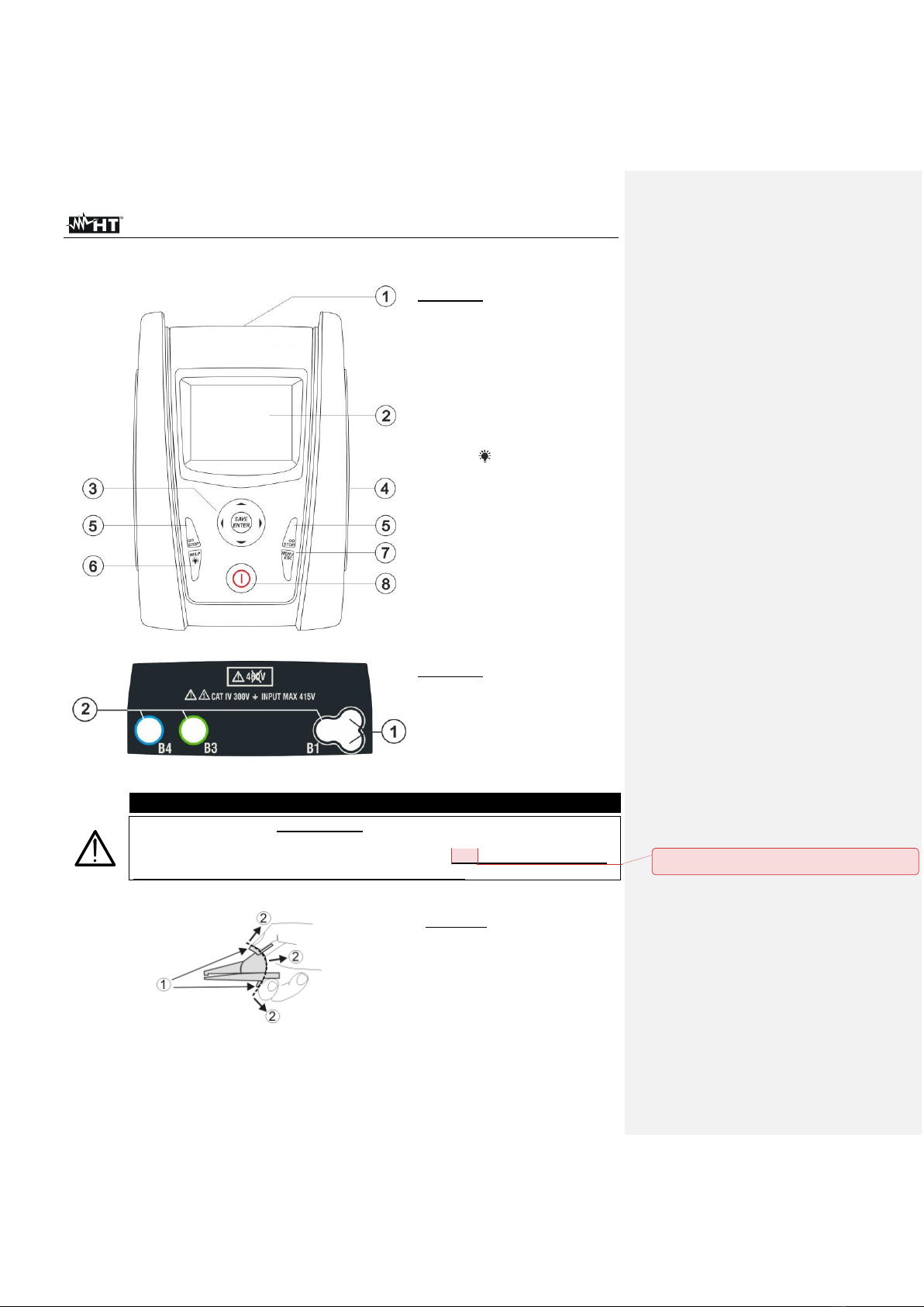
4. NOMENCLATURE........................................................................................................8
4.1. Instrument description .....................................................................................................8
4.2. Description of measuring leads........................................................................................8
4.3. Keyboard description.......................................................................................................8
4.4. Display description ..........................................................................................................9
4.5. Initial screen....................................................................................................................9
5. GENERAL MENU.......................................................................................................10
5.1. SET –Instrument settings .............................................................................................10
5.1.1. Language ............................................................................................................................... 10
5.1.2. Country................................................................................................................................... 11
5.1.3. Electrical system.................................................................................................................... 11
5.1.4. General settings..................................................................................................................... 11
5.1.5. Auto Start feature................................................................................................................... 12
5.1.6. Date and time......................................................................................................................... 12
5.1.7. Information ............................................................................................................................. 12
6. OPERATING INSTRUCTIONS...................................................................................13
6.1. AUTO: Automatic test sequence (Ra , RCD, M)........................................................13
6.1.1. Anomalous situations............................................................................................................. 20
6.2. DMM: Digital multimeter function...................................................................................21
6.3. RPE: Continuity of protective conductors.......................................................................23
6.3.1. TMR mode ............................................................................................................................. 25
6.3.2. > < mode............................................................................................................................. 26
6.3.3. Anomalous situations............................................................................................................. 27
6.4. Lo: Continuity of protective conductors with 10A.........................................................28
6.4.1. Anomalous situations............................................................................................................. 29
6.5. M: Measurement of insulation resistance....................................................................30
6.5.1. TMR mode ............................................................................................................................. 34
6.5.2. AUTO mode ........................................................................................................................... 35
6.5.3. Anomalous situations............................................................................................................. 36
6.6. RCD: Test on differential switches.................................................................................39
6.6.1. AUTO mode ........................................................................................................................... 42
6.6.2. AUTO mode ....................................................................................................................... 43
6.6.3. x½, x1, x5 modes................................................................................................................... 44
6.6.4. mode ................................................................................................................................. 45
6.6.5. Anomalous situations............................................................................................................. 46
6.7. LOOP: Line/Loop impedance and overall earth resistance ............................................49
6.7.1. Test types............................................................................................................................... 52
6.7.2. Test cable calibration (ZEROLOOP)...................................................................................... 54
6.7.3. STD Mode –Generic test ...................................................................................................... 56
6.7.4. Br.Cap mode –Verification of the breaking capacity of protection devices .......................... 58
6.7.5. TripT - Verification of protection coordination........................................................................ 60
6.7.6. Ra 2-wire test - Verification of protection against indirect contacts ................................... 62
6.7.7. Ra 3-wire test - Verification of protection against indirect contacts ................................... 64
6.7.8. Verification of protection against indirect contacts (IT systems)............................................ 66
6.7.9. Verification of protection against indirect contacts (TT systems) .......................................... 67