HT GroundTest M71 User manual

Copyright HT ITALIA 2016 Release EN 2.00 - 10/05/2016
ENGLISH
User manual

GroundTest M71
EN – 1
Table of contents:
1.SAFETY PRECAUTIONS AND PROCEDURES.........................................................2
1.1.Preliminary instructions..................................................................................................... 3
1.2.During use ........................................................................................................................ 3
1.3.After use ........................................................................................................................... 3
1.4.Definition of measurement category (OVERVOLTAGE) .................................................. 4
2.GENERAL DESCRIPTION..........................................................................................5
3.PREPARING THE INSTRUMENT...............................................................................5
3.1.Initial check ....................................................................................................................... 5
3.2.Power supply .................................................................................................................... 5
3.3.Calibration......................................................................................................................... 5
3.4.Storage ............................................................................................................................. 5
4.WORKING INSTRUCTIONS .......................................................................................6
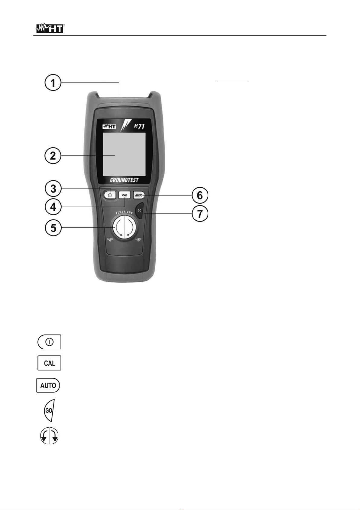
4.1.Instrument description ...................................................................................................... 6
4.2.Function keys description ................................................................................................. 6
4.2.1.Switching on............................................................................................................................... 7
4.2.2.Auto Power OFF ........................................................................................................................ 7
4.3.Auto mode ........................................................................................................................ 7
4.4.EARTH 2W:Two-wire earth resistance measurement ...................................................... 8
4.4.1.EARTH 2W- Zero setting of cables ........................................................................................... 8
4.4.2.EARTH 2W- Measurement procedure..................................................................................... 10
4.4.3.Message description for EARTH 2W measurement................................................................ 12
4.5.EARTH 3W: Three wire earth resistance measurement................................................. 13
4.5.1.EARTH 3W- Zero setting of cables ......................................................................................... 13
4.5.2.EARTH 3W- Measurement procedure..................................................................................... 15
4.5.3.Message description for EARTH 3W measurement................................................................ 17
5.MAINTENANCE ........................................................................................................19
5.1.General ........................................................................................................................... 19
5.2.Battery replacement........................................................................................................ 19
5.3.Cleaning.......................................................................................................................... 19
5.4.End of life........................................................................................................................ 19
6.TECHNICAL SPECIFICATIONS ...............................................................................20
6.1.Technical features .......................................................................................................... 20
6.1.1.Safety standards...................................................................................................................... 21
6.1.2.General features ...................................................................................................................... 21
6.2.Environment.................................................................................................................... 21
6.2.1.Environmental conditions......................................................................................................... 21
6.3.Accessories .................................................................................................................... 21
7.SERVICE...................................................................................................................22
7.1.Warranty terms ............................................................................................................... 22
7.2.After sales service .......................................................................................................... 22
8.PRACTICAL REPORTS FOR ELECTRICAL TESTS................................................23
8.1.Earth resistance measurement in TT systems ............................................................... 23
8.2.Earth resistance measurement, volt ampere metric method .......................................... 24

GroundTest M71
EN – 2
1. SAFETY PRECAUTIONS AND PROCEDURES
This instrument was designed in compliance with the IEC/EN61557-1 and IEC/EN61010-1
guidelines relative to electronic equipment.
CAUTION
For your own safety and to avoid damaging the instrument you are
recommended to follow the procedures described in this manual and read
carefully all instructions preceded by this symbol .
Before and during measurements keep to the following instructions:
Do not take voltage or current measurements in wet places
Do not take measurements in the presence of explosive gas and combustibles or in
dusty places
Avoid any contact with the circuit under test even though you are not taking any
measurement
Avoid any contact with exposed metal parts, unused measuring terminals, circuits etc.
Do not take any measurement whenever anomalous conditions occur such as
deformations, breaks, leakages, blind display etc
Pay utmost attention when taking measurements of voltage higher than 25V in special
places (building yards, swimming pools, etc.) and higher than 50V in ordinary places
due to the risk of electric shock.
The following symbols are used in this manual:
CAUTION: refer to the instruction manual. An improper use may damage the
instrument or its components as well as endanger the user.
High voltage danger: risk of electric shock.
AC voltage or current
DC voltage
Double insulation.

GroundTest M71
EN – 3
1.1. PRELIMINARY INSTRUCTIONS
This instrument has been designed for use in environments with pollution degree
It can be used for voltage and current measurements on electrical installations with
CAT III 240V to earth and maximum voltage of 415V between inputs
The instrument can be used on electrical installations type TT, TN and IT industrial,
civil, medical, zoo-technical both under ordinary conditions where contact voltage limit
is 50V, and under special conditions where contact voltage limit is 25V
You are recommended to respect the usual safety regulations aimed at protecting you
against dangerous currents and protecting the instrument against improper use
Only the original accessories supplied along with the instrument guarantee compliance
with the safety standards in force. They must be in a good conditions and, if necessary,
replaced with identical ones
Do not test nor connect to any circuit exceeding the specified overload protection
Do not take measurements under environmental conditions exceeding the limits
indicated in this manual
Make sure that batteries are correctly installed.
1.2. DURING USE
You are recommended to read carefully the following instructions::
CAUTION
Failure to comply with warnings and instructions may damage the instrument
and/or its components as well as injure the operator.
When the instrument is connected to circuits never touch any unused terminal
Do not measure in the presence of external voltages. Although the instrument is
protected, an excessive voltage may cause malfunction
Avoid submitting the instrument to voltage while measuring (i.e. a test lead slipping off
the measuring point accidentally touching an energized point).
CAUTION
If the “low battery” symbol Errore. Non si possono creare oggetti dalla
modifica di codici di campo. is displayed during use interrupt testing, switch
off the instrument and replace batteries following the procedure described in
§ 5.2.
1.3. AFTER USE
Turn off the instrument pressing ON/OFF key after using it
If you expect not to use the instrument for a long time remove batteries.

GroundTest M71
EN – 4
1.4. DEFINITION OF MEASUREMENT CATEGORY (OVERVOLTAGE)
Standards IEC/EN61010-1 (Safety requirements for electrical equipment for measurement,
control and laboratory use, Part 1: General requirements) define what a measurement
category (usually called “overvoltage category”) is. At § 6.7.4: Measuring circuits it quotes:
Circuits are divided into the following measurement categories:
Measurement category IV is for measurements performed at the source of a low-
voltage installation.
Examples are electricity meters and measurements on primary excess current protection
devices and ripple control units.
Measurement category III is for measurements performed in the building installations.
Examples are measurements on distribution boards, circuit breakers, wiring, including cables,
bus-bars, junction boxes, switches, socket-outlets in the fixed installations, and equipment for
industrial use as well as some other equipment, for example, stationary motors with permanent
connection to fixed installations.
Measurement category II is for measurements performed on circuits directly
connected to the low voltage installations.
Examples are measurements on household appliances, portable tools and similar equipment.
Measurement category I is for measurements performed on circuits not directly
connected to MAINS.
Examples are measurements on circuits not derived from MAINS, and specially protected
(internally) MAINS-derived circuits. In the latter case, transient stresses are variable; for this
reason, the norm requires that the transient withstand capability of the equipment is made
known to the user.

GroundTest M71
EN – 5
2. GENERAL DESCRIPTION
The instrument is capable of performing the following measurements:
EARTH 2W: Two-wire earth resistance measurement .
EARTH 3W: Three-wire earth resistance measurement.
3. PREPARING THE INSTRUMENT
3.1. INITIAL CHECK
This instrument was checked both mechanically and electrically prior to shipment.
All possible cares and precautions were taken to let you receive the instrument under
perfect conditions.
Notwithstanding we suggest you to check it rapidly to check any damage which may have
occurred during transport. Should it be the case please contact immediately the
manufacturer HT or your local dealer.
Make sure that all standard accessories mentioned in the enclosed packing list are
included in the packaging. In case of discrepancies contact your dealer.
Should you have to return back the instrument for any reason please follow the
instructions mentioned in § 7.
3.2. POWER SUPPLY
The instrument is powered by batteries (see § 6.1.2). When batteries are low, the low
battery indication is displayed. To replace/insert batteries follow the instructions indicated
in § 5.2
3.3. CALIBRATION
The instrument complies with the technical specifications contained in this manual and
such compliance is guaranteed for 12 months from purchase date.
3.4. STORAGE
After a period of storage under extreme environmental conditions exceeding the limits let
the instrument resume normal measuring conditions before using it (see § 6.2.1).

GroundTest M71
EN – 6
4. WORKING INSTRUCTIONS
4.1. INSTRUMENT DESCRIPTION
CAPTION:
1. Inputs
2. Display
3. ON/OFF key
4. CAL key
5. Switch of test mode
6. AUTO key
7. GO key
Fig. 1: Instrument's front panel
4.2. FUNCTION KEYS DESCRIPTION
ON/OFF Key to switch on and off the instrument.
CAL key to effect zero setting of cables under modes EARTH-2W e EARTH-
3W.
AUTO key to start/stop the mode detecting critical measuring conditions (high
electric noise) with automatic updating of measuring time.
GO key to start measurement.
Switch to select measuring mode.

GroundTest M71
EN – 7
4.2.1. Switching on
When switching on the instrument a brief tone is audible along
with display of all segments for about one second.
Subsequently the last firmware version as well as the last
selected measuring mode are displayed before switching off.
4.2.2. Auto Power OFF
To save battery life the instrument automatically turns off 5 minutes after last pressure of
keys. To resume operation turn on the instrument pressing the start key.
4.3. AUTO MODE
Starting up this mode the instrument will alter the measuring time to fit to the testing
conditions detected.
CAUTION
If the instrument detects an “electrical noise” lower than 0.5Vrms before
testing, it will adopt the “standard” test duration (approx. 13 s)
If the instrument detects an “electrical noise” higher than 0.5Vrms before
testing, it will extend the test duration (approx. 25s) to increase the
outcome stability even under severe measuring conditions

GroundTest M71
EN – 8
4.4. EARTH 2W:TWO-WIRE EARTH RESISTANCE MEASUREMENT
4.4.1. EARTH 2W- Zero setting of cables
CAUTION
The instrument can be used for voltage and current measurements on
installations with overvoltage category equal to CAT III 240V to earth and
maximum voltage of 415V between inputs. Do not connect the instrument to
installations whose voltages exceed the limits indicated in this manual.
Exceeding such limits may cause electric shock to the user and damage the
instrument.
CAUTION
The values for cable zeroing constants under modes EARTH-2W and EARTH-
3W are stored into separate and independent cells.
Fig. 2: Instrument’s wiring for zero setting of cables under mode EARTH-2W
1. Press the instrument's start key
2.
Select function EARTH 2W pressing the left arrow key.
3. Connect the red cable, the blue cable and the green cable to the corresponding
instrument's input terminals. The instrument shall keep the same operating features
during all measurement stages. Any cable extension or replacement as well as
additional crocodiles may nullify previous zero setting so requiring to repeat such a
setting procedure before effecting further measurements.
4. Connect the crocodiles to the test leads.
5. Short-circuit the measuring cables' ends (see Fig. 2) paying attention that the
crocodiles' metal parts make proper contact to each other. To get a safe connection
one of the rods provided with the instrument can be used..

GroundTest M71
EN – 9
6.
After pressing the CAL key the instrument carries out zero setting of cables'
resistance (this procedure takes approx. 30sec). Cables with a resistance up
to 2can be calibrated.
CAUTION
When “Measuring…” is displayed the instrument is effecting measurement.
During this phase do not disconnect test leads from the instrument.
7. At the end of the test the measured value
is stored by the instrument and used as
OFFSET (that is to say deduced from all
EARTH 2W measurements) for all
subsequent measurements till a further
zero setting. The instrument emits a
double sound tone indicating the positive
outcome for zero setting and displays
again the initial screen by the symbol
CAL.
Symbol CAL:
indicates that the
instrument was
calibrated; this
symbol is
displayed for each
subsequent
measurement
even though the
instrument is
switched off and
on again.
8. If during cables' zero setting the value
measured is higher than 2the
instrument interrupts such setting
procedure, removes the previous offset
value and does not display the symbol
CAL until a cables' zero setting is
successfully carried. out The instrument
emits a long sound tone indicating the
unsuccessful setting outcome and has
been displaying a screen similar to the
side one for about 2 seconds, then it
displays a default screen.
Note: this procedure can be used also to
cancel the last value stored for cables'
zero setting.

GroundTest M71
EN – 10
4.4.2. EARTH 2W- Measurement procedure
CAUTION
The instrument can be used for voltage and current measurements on
installations with overvoltage category equal to CAT III 240V to earth and
maximum voltage of 415V between inputs. Do not connect the instrument to
installations whose voltages exceed the limits indicated in this manual.
Exceeding such limits may cause electric shock to the user and damage the
instrument.
Fig. 3: Example of instrument's wiring for two-wire earth measurement
Fig. 4: Example of instrument's wiring for 2-wire earth measurement (only for TT systems).
Whenever it is not possible to drive rods into the ground to take a three-wire
measurement (i.e. In historical centres) it is possible to use the simplified two-wire
method which gives an excess value for the sake of safety
To carry out the test a suitable auxiliary rod is necessary; a rod is defined “suitable”
when its earth resistance is negligible and is independent of the earth installation under
test
In Fig. 3 a lamp post is used as auxiliary rod. However a water pipe or any metal body
driven into the ground is suitable provided that the above mentions requirements are
met
Only in case of a TT system a neutral conductor can be used as auxiliary earth rod
(see Fig. 4).

GroundTest M71
EN – 11
CAUTION
The instrument displays the sum value of RA+RT as result. Therefore the
measurement achieved is:
The closer to RA(prospective value) the more negligible the value RTof the
auxiliary earth rod with respect to RAitself
Increased “for the sake of safety” by RTthat is to say if the value of RA+RT
results to be coordinated with protective conductors, it will be far more
coordinated than that thanks to RA.
1. Press the instrument's start key.
2. Select function EARTH 2W pressing the left arrow key.
3.
If the circuit under test is assumed to be affected by electric noise press the
AUTO key to select the corresponding mode.
4. Connect the red cable and the green cable into the corresponding instrument's input
terminals.
5. Connect the crocodiles to the test leads.
6. When necessary (symbol CAL missing or use of a new set of cables) carry out zero setting
of cable resistance (see § 4.4.1)
7. Connect the instrument's terminals to the circuit under test (see Fig. 4 and Fig. 3).
8.
Press GO key to start measurement.
9. Display example of earth resistance
and disruptive voltage measured
values.
Should disruptive voltage have been
higher than 0.5V, it would be advisable
to start AUTO mode and repeat
measurement.
Value measured for
earth resistance
RA+RT
Value measured for
disruptive voltage

GroundTest M71
EN – 12
4.4.3. Message description for EARTH 2W measurement
1. If the following condition is met:
RDISPLAYED < 0.11
the instrument displays the symbol Errore.
Non si possono creare oggetti dalla
modifica di codici di campo. indicating
that the reading may be affected by a
relative error higher than 30%.
2. If the following condition is met:
Disruptive voltage > 3.0V
the instrument displays the symbol Errore.
Non si possono creare oggetti dalla
modifica di codici di campo. indicating
that the reading is carried out under critical
conditions.
3. If the following condition is met:
RMEASURED - RCABLES < - 0.03
the instrument displays the side screen and
emits a long sound tone indicating an
anomalous condition then displays the initial
screen again. This message indicates that
the measured resistance is lower than that
of measuring cables and that a further zero
setting procedure is to be carried out.
4. When measuring, if terminals' voltage is
higher than 6V, the instrument does not
effect the test. A long sound tone is emitted
indicating an anomalous condition and the
side screen is displayed for 5 seconds (S-E
indicates between which inputs voltage was
detected), then the instrument displays the
initial screen.
Value of input
voltage
5. Should the resistance value be higher than
the full scale, the instrument emits a long
sound tone indicating the anomalous
condition and displays a screen similar to
the side one. The same indication may also
highlight that measuring cables are
disconnected or open.

GroundTest M71
EN – 13
4.5. EARTH 3W: THREE WIRE EARTH RESISTANCE MEASUREMENT
4.5.1. EARTH 3W- Zero setting of cables
CAUTION
The instrument can be used for voltage and current measurements on
installations with overvoltage category equal to CAT III 240V to earth and
maximum voltage of 415V between inputs. Do not connect the instrument to
installations whose voltages exceed the limits indicated in this manual.
Exceeding such limits may cause electric shock to the user and damage the
instrument.
CAUTION
The values for cable zeroing constants under modes EARTH-2W and EARTH-
3W are stored into separate and independent cells.
Fig. 5: Instrument's wiring for cables' zero setting under EARTH-3W mode
1. Press the instrument's start key.
2. Select function EARTH-3W pressing the right arrow key.
3. Connect the red cable, the blue cable and the green cable to the corresponding
instrument's input terminals. The instrument shall keep the same operating features
during all measurement stages. Any cable extension or replacement as well as
additional crocodiles may nullify previous zero setting so requiring to repeat such a
setting procedure before effecting further measurements.
4. Connect the crocodiles to the test leads.
5. Short-circuit the measuring cables' ends (see Fig. 5) paying attention that the
crocodiles' metal parts make proper contact to each other. To get a safe connection
one of the rods provided with the instrument can be used.
6.
After pressing the CAL key the instrument carries out zero setting of cables'
resistance (this procedure takes approx. 30sec). Cables with a resistance up
to 0.3can be calibrated.

GroundTest M71
EN – 14
CAUTION
When “Measuring…” is displayed the instrument is effecting measurement.
During this phase do not disconnect test leads from the instrument.
7. At the end of the test the measured value
is stored by the instrument and used as
OFFSET (that is to say deduced from all
EARTH 3W measurements) for all
subsequent measurements till a further
zero setting. The instrument emits a
double sound tone indicating the positive
outcome for zero setting and displays
again the initial screen by the symbol
CAL.
Symbol CAL:
indicates that the
instrument was
calibrated; this
symbol is
displayed for each
subsequent
measurement
even though the
instrument is
switched off and
on again.
8. If during cables' zero setting the value
measured is higher than 0.3the
instrument interrupts such setting
procedure, removes the previous offset
value and does not display the symbol
CAL until a cables' zero setting is
successfully carried. out The instrument
emits a long sound tone indicating the
unsuccessful setting outcome and has
been displaying a screen similar to the
side one for about 2 seconds, then it
displays a default screen.
Note: this procedure can be used also to
cancel the last value stored for cables'
zero setting.

GroundTest M71
EN – 15
4.5.2. EARTH 3W- Measurement procedure
CAUTION
The instrument can be used for voltage and current measurements on
installations with overvoltage category equal to CAT III 240V to earth and
maximum voltage of 415V between inputs. Do not connect the instrument to
installations whose voltages exceed the limits indicated in this manual.
Exceeding such limits may cause electric shock to the user and damage the
instrument.
Fig. 6: Instrument's wiring for three-wire earth measurement
For small sized installations, place the ampere metric probe (terminal H, blue wire) at a
distance equal to five times the diagonal of the earth installation and the volt metric
probe (terminal S, red wire) at a distance equal to about 2.5 times the diagonal of the
earth installation
For large sized installations, place the ampere metric probe (terminal H, blue wire) at a
distance equal to the diagonal of the earth installation and the volt metric probe
(terminal S, red wire) at a distance equal to about 0.5 times the diagonal of the earth
installation
In the latter case several measurements shall be carried out moving the volt metric
probe back and forth (along the measurement direction) with respect to the middle
point and checking that the result is nearly constant.

GroundTest M71
EN – 16
1. Press the instrument's start key.
2. Select function EARTH 3W pressing the right arrow key.
3.
If the circuit under test is assumed to be affected by electric noise press the
AUTO key to select the corresponding mode.
4. Connect the red cable and the green cable into the corresponding instrument's input
terminals.
5. Connect the crocodiles to the test leads.
6. When necessary (symbol CAL missing or use of a new set of cables) carry out zero setting
of cable resistance (see § 4.5.1)
7. Connect the instrument's terminals to the circuit under test (see Fig. 6).
8.
Press GO key to start measurement.
9. Display example of earth resistance
and disruptive voltage measured
values.
Should disruptive voltage have been
higher than 0.5V, it would be advisable
to start AUTO mode and repeat
measurement.
Value measured for
earth resistance
Value measured for
disruptive voltage

GroundTest M71
EN – 17
4.5.3. Message description for EARTH 3W measurement
1.If the following condition is met:
RDISPLAYED < 0.11
the instrument displays the symbol Errore.
Non si possono creare oggetti dalla
modifica di codici di campo. indicating that
the reading may be affected by a relative
error higher than 30%.
2.If the following condition is met:
Disruptive voltage > 3.0V
the instrument displays the symbol Errore.
Non si possono creare oggetti dalla
modifica di codici di campo. indicating
that the reading is carried out under critical
conditions.
3.If the following condition is met:
RMEASURED - RCABLES < - 0.03
the instrument displays the side screen and
emits a long sound tone indicating an
anomalous condition then displays the initial
screen again. This message indicates that
the measured resistance is lower than that
of measuring cables and that a further zero
setting procedure is to be carried out.
4. When measuring, if terminals' voltage is
higher than 6V, the instrument does not
effect the test. A long sound tone is emitted
indicating an anomalous condition and the
side screen is displayed for 5 seconds (S-E
indicates between which inputs voltage was
detected), then the instrument displays the
initial screen.
Value of input
voltage
5. Should the resistance value be higher than
the full scale, the instrument emits a long
sound tone indicating the anomalous
condition and displays a screen similar to
the side one. The same indication may also
highlight that measuring cables are
disconnected or open.

GroundTest M71
EN – 18
6. If the volt metric circuit (terminal S) shows a
too high resistance value the side message
is displayed.
Check connection of red and green wires as
well as their integrity.
If the problem still exists connect two or
more auxiliary rods in parallel and pour
some water around the rods in order to
make a better volt metric probe (that is the
ground rod connected to the red wire).
7. If the ampere metric circuit (terminal H)
shows a too high resistance value the side
message is displayed.
Check connection of blue and green wires
as well as their integrity.
If the problem still exists connect two or
more auxiliary rods in parallel and pour
some water around the rods in order to
make a better ampere metric probe (that is
the ground rod connected to the blue wire).
8. If the ampere- and volt-metric circuits
(terminal S and H) show a too high
resistance value the side message is
displayed.
Check connection of blue, red and green
wires as well as their integrity.
If the problem still exists connect two or
more auxiliary rods in parallel and pour
some water around the rods in order to
make a better ampere metric probe (that is
the ground rod connected to the blue
wire).repeating the procedure for the volt
metric probe (that is the ground rod
connected to the red wire).

GroundTest M71
EN – 19
5. MAINTENANCE
5.1. GENERAL
1. This instrument is a precision meter. During its use and storage you are recommended
to keep the instructions listed in this manual to avoid any harm or danger
2. Do not use the instrument in excessively wet environments and under high
temperatures. Do not expose it to direct sunlight
3. Always switch the instrument off after use. If you expect not to use the instrument for a
long period remove batteries to avoid any acid leakage which may damage the
instrument's inner circuits.
5.2. BATTERY REPLACEMENT
The display of the symbol indicates that batteries shall be replaced.
CAUTION
Such an operation shall be carried out by qualified people only. Before replacing
batteries disconnect test leads from the circuit under test to avoid electric shock.
1. Disconnect all cables from input terminals
2. Turn off the meter pressing ON/OFF key
3. Remove battery compartment cover
4. Remove all batteries and replace them with 4 units. having the same features (see §
6.1.2) keeping to the indicated polarity signs
5. Replace battery compartment cover
6. Use the appropriate battery disposal methods for Yr area
5.3. CLEANING
Clean the meter exclusively using a soft and dry cloth. Never use wet clothes, solvents,
water, etc.
5.4. END OF LIFE
Caution: the barred symbol of the rubbish bin shown on the equipment indicates
that, at the end of its useful life, both the products and its accessories shall be
collected separately from other waste and correctly disposed.
Table of contents
Other HT Test Equipment manuals
Popular Test Equipment manuals by other brands

Seaward
Seaward PAC3760 operating instructions

Lutron Electronics
Lutron Electronics DI-6300 Operation manual

Horizont
Horizont RANGER N80 Operating instruction

Transmille
Transmille 3200A Series Operation manual

Energy Recovery
Energy Recovery TurboCharger AT-95 manual

Kurth Electronic
Kurth Electronic KE7200 operating manual